These damages should not be underestimated as they pose a danger to Treppelwege users. What level of influence can be observed in relation to gravel grain size distribution on root development.
Tree roots
- Root functions
- Root development and growth
- Root systems
- Environmental influences on root architecture
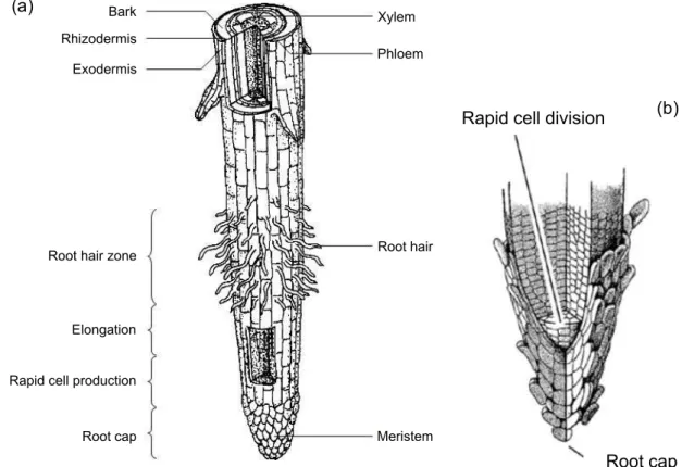
The part of the root behind the extension zone is capable of producing root hairs and is therefore called the root hair zone. The physical appearance of the roots changes in such soils, undergoing some thickening and shortening of the root sheath (Balder, 2000).
Pioneer vegetation
Poplar
The genus Populus has characteristics that are favorable for the investigation of the root behavior: the possibility of vegetative propagation by cuttings, the ability to produce root suckers and rapid initial development in the juvenile stages (Isebrands and Richardson, 2014). Nowadays it can also be found in the southern hemisphere, due to widespread plantings (Isebrands and Richardson, 2014).
Willow
Traffic areas
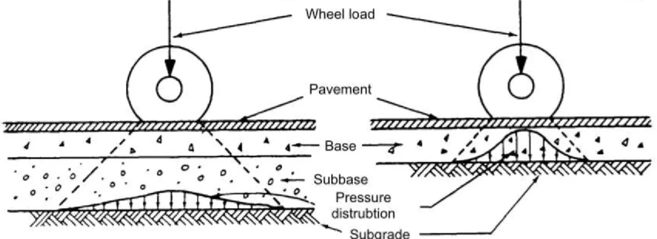
Common road structure
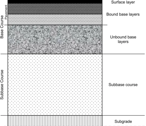
On top of the substrate is the underlayment, which separates the base layers from the underlayment. Frost susceptibility classes help with the selection of minimum thickness of the base layer (Reichwein, 2002).
Treppelwege
42 sites have been selected as representative samples for the course of the towpaths in Austria. A correlation of vegetation and damage intensity resulted in a high damage potential of poplars (Weissteiner, 2015).
Interaction of plants and infrastructure
Infrastructure affects vegetation
This results in the rearrangement of soil particles and a reduction in the fraction of medium and coarse pores (Reichwein, 2002). Modified soil temperature and different water content can increase root growth and secondary thickening.
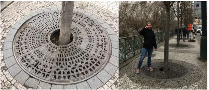
Vegetation affects infrastructure
According to Robert Day, roots traveling under pavement begin their normal growth activities when they reach undisturbed soil (Randrup et al., 2001). Damage can occur in the first years after infrastructure construction (Kopinga, 1994), resulting in huge maintenance costs and illustrating the importance of planning and management before road construction (Randrup et al., 2001; Reichwein, 2002).
Mitigation and prevention
Mitigation methods
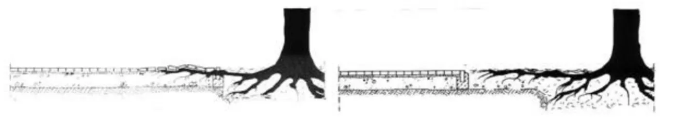
The boundary to the structure of the road is further removed from the tree trunk and the new tree zone is filled with plant substrate (fig. 6). A disadvantage is the high level of tree care and increased protection of the tree zone (Reichwein, 2002). This cost-effective method allows for some surface adjustment as tree roots thicken.
Occasionally, changing the surface without removing tree roots is only possible by adding material and raising the surface level in the immediate vicinity of the tree. This may include replacement of the top layer, the boundary of the tree zone (curved pavements) or the entire road structure, which is necessary when a tree is to be completely removed (Costello and Jones, 2003; Reichwein, 2002).
Prevention methods
They are solid and change the growth path of the roots sideways and/or downwards. The applied principle is that the tips of the roots can grow through the barrier, but their radial growth is limited by the size of the holes in the traps (Randrup et al., 2001). Circular barriers surround the roots which limit the vertical growth and direct the development to deeper layers of the soil (Costello et al., 1997; Randrup et al., 2001).
The next chapter describes the setting of the field experiment in Groß Enzersdorf and the progress in gathering the necessary information to answer the research questions. Penetration of the roots of riparian trees into matrix stone mixtures with different grain sizes" (2016), in which he presents the results of the first phase of the field experiment.
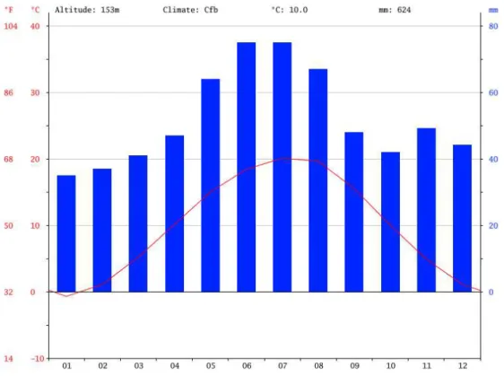
Groß Enzersdorf
The information about the initial set-up, the structure and the construction process is based on Michael Müllner's master's thesis "Tree roots as a cause of damage to paved paths. The monthly mean temperature of -0.7°C is documented for January, making it the coldest time of the year (Merkel, 2017).
Experimental setup
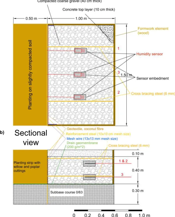
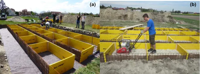
A top view and cross-section of the road construction box arrangement with its different elements is shown in Fig.12. This overview includes the humidity sensors that have been placed in six of the 18 road construction cabinets. Three rows of six road construction boxes each were placed at a distance of 0.5 m on top of the drain geomembrane, facing in one direction (Fig. 13a).
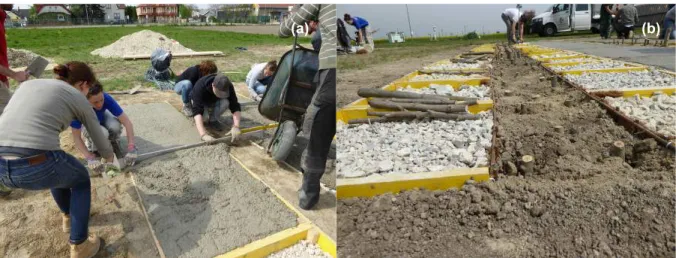
First, a layer of gravel mixtures with a depth of 20 cm was installed, which was compacted with a vibro plate. Three of the 18 boxes were filled with substrate of grain size 08/32, which was stabilized with 3% cement.
Biomass extraction
- Aboveground biomass
- Underground biomass - planting strips
- Underground biomass - road structure boxes
- Underground biomass - substrate boxes
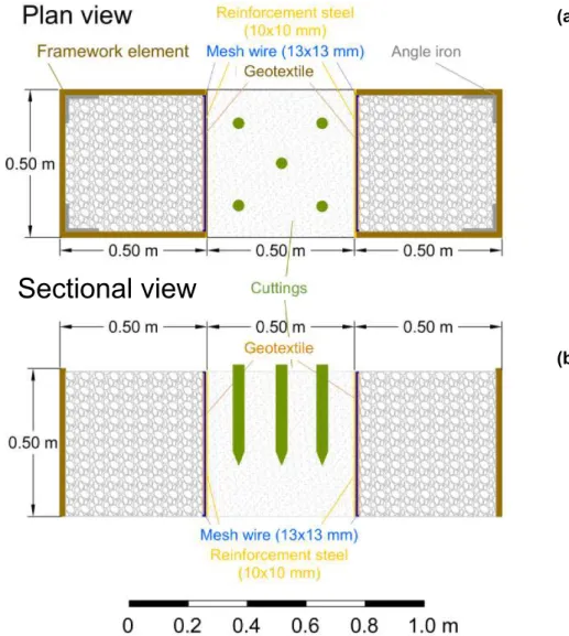
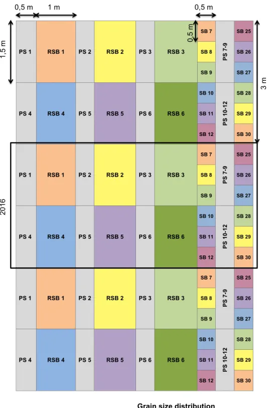
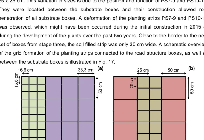
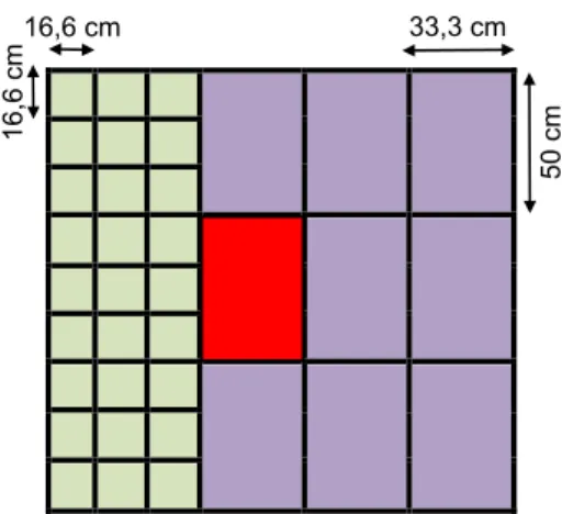
The detailed description of the method is structured according to above-ground biomass, underground biomass of the plant strips, the road construction cabinets and the substrate troughs. A schematic overview of the grid formation of the plant strips that are connected to the road construction boxes, as well as between the substrate trays, is shown in Fig. By sieving the soil, the root biomass was collected and stored in plots (Fig. 19d).
After excavating the plant strips, we started collecting the biomass from the road construction cabinets. Then the roots were categorized by root diameter and weighed (fine, medium and coarse roots).
Root scans
Once the roots were collected, the biomass was dried in the same way as the roots were extracted from the plant strips. Occasionally the roots, which grew close to the bottom, were covered with mud and had to be soaked in water before being dried at 80°C in the oven until constant weight. The substrate and roots were dug up using small shovels and garden claws (Fig. 22b).
Any remaining soil was removed before the roots were categorized and weighed according to their diameter. Divided into smaller parts, the roots were placed in a Perspex container filled with distilled water (Fig. 26a).
Sieving analysis
The results are sorted by aboveground biomass, plant strip roots, road structure box roots and substrate box roots. For the analysis of the temporal development of the field experiment, the collected data are compared with the results of the first phase of the field experiment in 2015.
Aboveground biomass
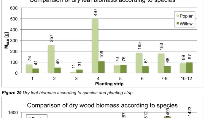
The findings of the dry aboveground biomass analysis show that the accumulated poplar leaf biomass was greater than the willow leaf biomass, with the exception of PS3, PS5 and PS10-12 (Fig. 29), although the species were outnumbered by willow cuttings. The dry wood biomass of the willow cuttings was usually higher than the dry poplar biomass, except for PS2 and PS4 (Fig. 30). One poplar cutting clearly grew larger than the other cuttings with a dry wood biomass of 1100 g.
In the ratio of dry leaf and wood biomass, we observe a positive correlation between dry wood and leaf biomass (Figure 31). More detailed information on the development of cuttings can be found in the appendix.
Root biomass
Planting strips
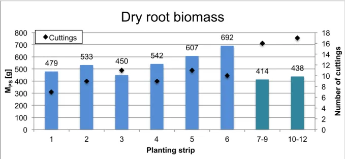
Since the spatial distribution is as relevant as the amount itself, the biomass was analyzed according to the levels in which it developed, as shown in fig. In the first level, the least amount of biomass was found, except in PS8, which contained more roots in the second level. Reasons for this development may be higher moisture levels close to the drainage geomembrane as well as the penetration depth of cuttings of approx. 30 cm.
The results of the level analysis were paired with those from the diameter categories to gain insight into the distribution of the fine, medium and coarse roots within the levels (Fig. 35). An exception to this was PS1, where the plants' belowground biomass (479 g) was almost the same as their aboveground biomass (635 g).
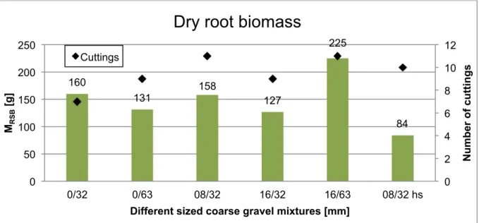
Road structure boxes
These results differ when the biomass is related to the root biomass of the connected plant strips (fig. 38). With the exception of substrates 16/32, a steady increase in root biomass was observed with increasing depth. A continuous decrease in root biomass was observed with increasing distance from the plant strip in the mixtures 16/63 and 08/32 hs.
The root biomass was divided according to the level of occurrence and the root thickness, as in Fig. Neglecting the third level changed little in the outcome of the root biomass ratio of the 08/32 hs mixture, which remained the substrate with the smallest share of roots.
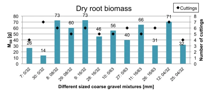
Substrate boxes
A drastic change was observed in the relative biomass of mixtures 0/32 and 16/63, which had large proportions of third-level roots. It is noteworthy that none of the boxes filled with the same substrate have the same relative root biomass. Although the substrate boxes held less root biomass compared to the road structure boxes, the amount of intermediate roots was noticeably higher in the substrate boxes.
The analysis of the horizontal root distribution showed that the development of the biomass in the substrate boxes corresponded to the development in the road structure boxes (Fig. 48). All substrates had high biomass proportions of roots between 0 and 10 mm in the third level.
Root scans
The first level contained almost exclusively fine roots and the amount of medium roots was remarkably high in the third level. The results of the root scans did not necessarily correspond to the assessment of the total root biomass. For example, the hydraulically stabilized mixture had the second highest proportion of root biomass at 109,779 cm, while it had the least amount of biomass in the total biomass analyses.
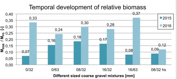
Temporal development of biomass
The temporal development of the relative biomass of the roots was analyzed according to the gravel mixtures of different sizes, as shown in Fig. Root biomass development, root spatial distribution and temporal development were analyzed. 160 g of root biomass was extracted from the substrate, which translated into a relative biomass of 33% once attached to the roots from the associated planting belt.
The proportion of fine fragments in the substrate could be a possible explanation for the relatively high root biomass at the third level. Looking at the distribution of roots by column and root diameter, most of the root biomass was found in the third column and consisted of fine roots, followed by medium roots in the first column. The relative biomass of roots without third tier roots was only 18%, resulting in less relative biomass extracted from the substrates.
The results should be useful for the final extraction of root biomass in 2019, when the success rates of the different sizes of gravel mixtures need to be determined.