BEFORE using the equipment, make sure you clearly understand the meanings of the symbols and follow the necessary safety precautions. No part of this manual may be reproduced without the prior written permission of the publisher. The fault is outside the scope of the warranty conditions, which are specifically described in the user manual.
The defect is the result of incorrect handling, misuse or unauthorized modification or repair of the equipment by the customer. This EULA permits you to install one copy of this software on one piece of equipment. If this software is used for purposes other than those described in the user manual or specifications. ii).
If Anritsu suffers any damage or loss, financial or otherwise, as a result of your breach of the terms of this EULA, Anritsu shall be entitled to claim proportionate damages from you. The Signal Quality Analyzer Series Operation Manuals consist of separate documents for the Installation Manual, Mainframe, Remote Control, Module(s) and Control Software as shown below.
Overview
Product Overview
The MU181040A is a plug-in module that can be built into the host computer of the signal quality analyzer series. It can measure a variety of samples within the operating frequency range, including PRBS samples, data, zero shift, mixed and sequential samples. This module is therefore useful for research, development and production of various types of digital communication equipment, modules and devices.
Support a variety of applications such as research, development and device manufacturing by installing options.
Product Composition
- Standard composition
- Options
- Application parts
Specifications
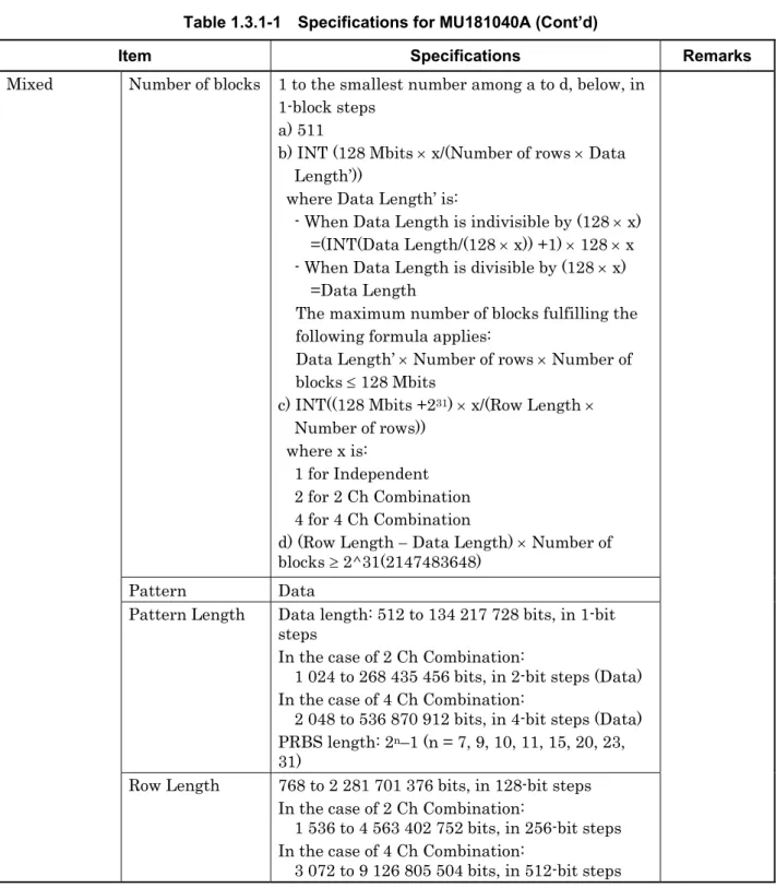
- Specifications for MU181040A
- Specifications for MU181040B
In the case of 2 Ch combination, the number of blocks at the lowest layer is 128. In the case of 4-can combination, the number of blocks at the lowest layer is 256. In the case of Independent, when the pattern length is 127 bits or less, specify the length as an integer multiple so that it becomes 128 bits or more.
Monitor output Number of output 2 (Data monitor, XData monitor). Data Input to Data Monitor Output, XData Input to XData Monitor Output). Input data PRBS/Data/Zero-Sub/Mixed/Sequence NRZ (equivalent to tag ratio 1/2). you can set POS and NEG switching. Monitor output Number of output 2 (Data monitor, Data monitor). Data input to data monitor output, data input to data monitor output).
Input Data PRBS/Data/Zero-Sub/Mixed/Sequence NRZ (equivalent to 1/2 tag ratio) Clock Polarity. you can set POS and NEG switching. NRZ auto search input format. when there is at least one transit bit for every 128 bits, the ratio of the number of rising/falling edges to the sample length is 1:5 or more, and the mark ratio is 1/8 to 7/8) Input sensitivity typ. continued).
Preparation before Use
Installation to Signal Quality Analyzer
For information on installing the MU181040A on the Signal Quality Analyzer and applying power, see Chapter 2 "Preparing for Use" in the Signal Quality Analyzer Series Installation Guide.
How to Operate Application
Preventing Damage
CAUTION
Panel Layout and Connectors
- Panel Layout
- Inter-Module Connection
Make sure you are using the 3-pin power cord that came with the host computer and the 3-pin power outlet. Connect the MU181020A data output connector and the MU181040A data input connector with a coaxial cable. Also connect the XData MU181020A output connector and the XData MU181040A input connector with a coaxial cable.
Connect the output connector of the MU181020A clock and the input connector of the MU181040A clock with a coaxial cable. Please note that after initialization, all settings are returned to the initial factory settings. In order to protect the device from failure due to electrostatic discharge, a conductive plate should be installed on the work table, and the operator should wear an electrostatic discharge wrist strap.
Connect the ground end of the wrist strap to the circuit board or to the main computer's ground terminal. When removing the cable from the connector on the front panel of the device, be careful not to put too much stress on the connector.

Configuration of Setup Dialog Box
- Configuration of Entire Setup Dialog Box
- Operation Tab Windows
The configuration of the configuration dialog box when the MU181040A is inserted into a mainframe is shown below. Model generation method setting, auxiliary input/output selection and other settings can be configured in this tab window.

Operation Method
- Displaying Measurement Result
- Setting items when Gating is selected
- Setting items when Auto Sync is selected
- Setting items when Sync Control is selected
- Setting items when Condition is selected
- Setting items when Input is selected
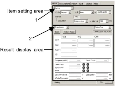
The setting items change according to the item selected in the drop-down list (“1” in the figure above) in the item setting area. The display items change according to the item selected in the drop-down list ("2" in the image above) in the results display area. This section describes the setting items when Gating is selected from the drop-down list in the item setting area ("1" in Figure 5.1-1).
1] Select the measurement period unit from the Unit list box and set the measurement period in the upper right text field. Select “Progressive” or “Immediate” from the Calculation list for the method of displaying measurement results in the middle. This section describes the setting items when Auto Sync is selected from the list box in the item setting area (“1” in Figure 5.1-1).
If the error rate exceeds the synchronization threshold in the synchronization gain condition, it is evaluated as a synchronization loss. On the other hand, if the error rate falls to the synchronization threshold or below the synchronization loss condition, it is evaluated as synchronization gain. This section describes the setting items when Sync Control is selected from the list box in the item setting area (“1” in Figure 5.1-1).
The test pattern synchronization methods that you can select from the Control list box vary depending on the test pattern selected on the Pattern tab. The frame detection pattern length varies depending on the test pattern selected in the Pattern tab window. This section describes the setting items when Condition ("1" in Figure 5.1-1) is selected from the list box in the item setting area.
This section describes the setting items when Input is selected from the list box in the subject setting area (“1” in Figure 5.1-1). The setting range of the setting points is limited by the input conditions specified in the Input tab window. This item is enabled when "Differential 50 Ohm" or "Differential 100 Ohm" is selected and "Alternative" is selected in the Input tab.
Normal 2 Ch Combination 4 Ch Combination
- Setting items when Error/Alarm is selected
- Setting items when Logging is selected
- Setting items and displayed items when histogram is selected
- When setting jitter-modulated signals
- Setting Measurement Conditions
- Gating area
- Auto Sync area
- Sync Control area
- Error/Alarm Condition area
- Setting Test Patterns
- Test Pattern type
- Setting PRBS pattern
- Setting Zero-Substitution pattern
- Setting Data pattern
- Setting Mixed pattern
- Setting Sequence pattern
- Mask selection
- Editing test pattern in Pattern Editor dialog box
- Setting Input Interface
- Input setting items (when MU181040A-001 is installed)
- Input setting items (when MU181040A-002 and MU181040B-002 are installed)
- Capturing Test Patterns
- Setting items in Pattern tab window
- Displaying captured test pattern (Bit Pattern)
- Displaying captured test pattern (Bitmap)
- Displaying captured test pattern (Block)
- Misc Function
- Setting Pattern Sequence
- Setting AUX Output
- Setting AUX Input
- Measurement Restart area
- Executing Auto Search
- Input setting items in Auto Search dialog box
- Executing Auto Adjust
- Input setting items in Auto Adjust dialog box
- ISI Measurement Function
- Displaying ISI measurement results in ISI window
- Restrictions on ISI measurement
- Eye Margin Measurement
- Eye Margin window
- Menu items
- How to perform Eye Margin measurement
- Eye Diagram Measurement
- Eye Diagram window
- Condition tab window
- Diagram tab window
- Condition tab window
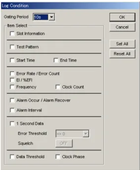
This section describes the setting items when Logging is selected from the list box in the results display area ("2" in Figure 5.1-1). The functions of the controls in the Bit Window Setup dialog box are as follows. The number of blocks in the pattern data edited in the Pattern Editor dialog box is displayed.
The length of 1 row of the pattern data edited in the Pattern Editor dialog box is displayed. The length of the data pattern edited in the Pattern Editor dialog box is displayed. The number of rows per block of the pattern data edited in the Pattern Editor dialog box is displayed.
3] Sets the test pattern for the block selected in the sequence pattern setting display area. 5] Set the pattern to be used for pattern matching in the pattern matching settings area. The Pattern Editor dialog box appears when [Edit] or [Pattern Edit]. in the case of a sequence pattern) you click.
The highlighted part in the Pattern View area can be edited in this dialog box. How to create and edit a test pattern in the Pattern Editor dialog box is described below. 1] Select the display format from the Format list box in the Pattern Editor dialog box.
1 Replaces the cursor position bit or bits in the selection area to "1". Reverse Reverses the cursor position bit or bits in the selection area. In the Model tab window, input test model data can be captured on the MU181040A.
This section describes how to capture and analyze a test pattern in the Sample tab window. A manual trigger can be executed when "Manual" is selected in the Trigger list box in the Status Setup dialog box. 4] Clicking [Set All] selects all check boxes of valid slots in the slot range.
The status of the automatic adjustment is displayed in the lower part of the results tab window.
![Figure 5.1.6-1 Items when Error/Alarm is selected [1] Select the measurement time display type](https://thumb-eu.123doks.com/thumbv2/pubdocnet/373131.44528/80.892.290.804.285.751/figure-items-error-alarm-selected-select-measurement-display.webp)


![Figure 5.1.2-1 Items when Auto Sync is selected [1] Specify whether to start resynchronization automatically when the](https://thumb-eu.123doks.com/thumbv2/pubdocnet/373131.44528/64.892.314.792.292.497/figure-items-auto-sync-selected-specify-resynchronization-automatically.webp)

![Figure 5.1.7-1 Items when Logging is selected [1] Click to start/stop logging.](https://thumb-eu.123doks.com/thumbv2/pubdocnet/373131.44528/86.892.342.808.345.792/figure-items-logging-selected-click-start-stop-logging.webp)
![Figure 5.1.8-1 Items when Histogram is selected [1] Click to ON/OFF the histogram result display](https://thumb-eu.123doks.com/thumbv2/pubdocnet/373131.44528/90.892.351.744.335.652/figure-items-histogram-selected-click-histogram-result-display.webp)
