In this work, the biomass-based precursor (biofuel) was demineralized and further used to produce activated carbon using two different activation methods: physical and chemical activation in which steam and potassium hydroxide were used, respectively. The bulk density of powdered chemical activated carbon and pelleted physical activated carbon is 0.128 t/m3 and 0.239 t/m3, respectively.
Research objective
Woody biomass and associated forest residues in particular can potentially be used as such a renewable resource. The bioliq® concept developed by KIT (Karlsruhe institute of Technology) is a three-step conversion process for the production of second-generation biofuels from biomass waste such as wheat straw.
Scope of research
Thesis layout
The last part of this chapter discusses literature review on previous research work by different researchers. Until a plant or tree dies, it will continue to use and store CO2 as fuel for growth.
Pyrolysis
Fast pyrolysis
Heating rates in fast pyrolysis are higher than compared to slow pyrolysis and are usually estimated based on reactor temperature, particle size, and residence time of the particles in the reactor. It was analyzed that with an increase in particle size between 300 m to 1500 m, bio-oil yield will decrease, but further increase in particle size will not affect bio-oil yield [11].
Slow pyrolysis
During a slow pyrolysis experiment, the biomass is heated until the desired (maximum) temperature is reached. In a study of Thuja (Tetraclinis articulata) wood samples by [23], it was shown that under isothermal pyrolysis conditions the holding time had a significant effect on the char yield only up to 120 minutes.
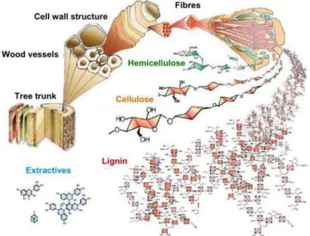
Chemical composition influencing on pyrolysis
A study [24] investigated the effects of lignocellulosic composition of different types of biomass using TGA. Two reaction phases were observed, which were attributed to the volatilization of the cellulosic (fast) and lignin (slow) components of the biomass.
Bio char technology
Applications of biochar
Biochar can be used as a carbon fertilizer, compost, peat substitute in potting soil, plant protection and compensatory fertilizer for trace elements. Compost can be used as a very effective substitute for peat in potting soil, greenhouses and nurseries.
Activated carbon
- Thermal or physical activation
- Chemical activation
- Classification of activated carbon
- Gas phase applications
- Liquid phase applications
For liquid phase applications, activated carbon is used in both forms, such as granular or powdered. Activated carbon is also used to remove color from sugar during the refining process.
Worldwide drinking water problem
Removal of water pollutants and their effects on living organisms
In this work, activated carbon will be used in liquid phase applications specifically focused on drinking water treatment. Using activated carbon to remove heavy metals from water will minimize health related diseases.
Arsenic in ground water: a worldwide problem
Literature review
The activated carbon was prepared using KOH as an activating agent, the char produced by carbonization at 700 C for 1 hour in an inert atmosphere. In his work, different parameters were varied to check their effect on BET surface area of activated carbon. Azargohar and Dalai used biochar as a pyrolysis plant precursor for the production of activated carbon using physical (steam) and chemical (potassium hydroxide).
Activated carbon prepared by chemical activation of Physic nut pyrolyzed carbon at 800 °C with KOH and achieved a maximum surface area of 530 m2/g [49].
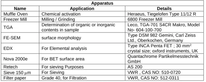
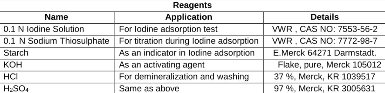
Materials
This chapter includes the experimental procedures used in this work for biochar production, biochar demineralization, chemical activation, physical activation, iodine and N2 adsorption analysis.
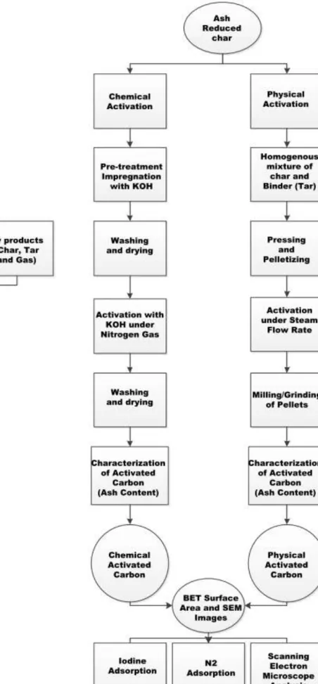
Methods
- Biochar production
- Demineralization of biochar
- Chemical activation
- Physical Activation
- Pellets formation
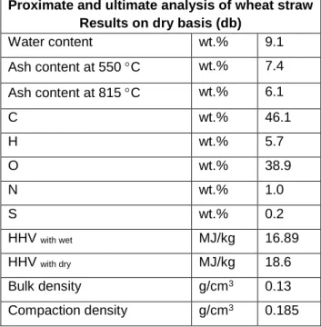
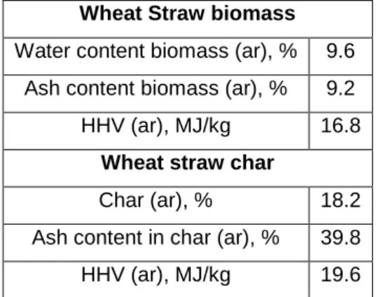
The bioliquid fast pyrolysis flow sheet is shown in Figure 3.2, the proximate and final analysis performed for the biomass feedstock results are shown on a dry basis in Table 3.3. In this work, activation was carried out at different temperatures (450, 675 and 700 C) with impregnation ratios such as 1.63:1 and 4:1 (KOH/Biochar) (''to clarify for chemical heat treatment, KOH ground is used with In this work, the porous bottom of the case with 100 m holes was used, but carbon has particles of different sizes, particles with a size smaller than 100 m can easily pass through the case and creates mass loss.
In this work, pellets were activated at 750 C in a vertical tube reactor, where the nitrogen flow rate (500 ml/min) passed through the pellet bed at the start and end of activation and the steam flow rate (75 ml/min min) passed through the bed during activation .
Characterization of activated carbon
Iodine adsorption (Liquid phase adsorption)
Initially, 5 – 10 g of pellets were put into the box with a porous bottom, then the box was attached to the reactor tube. The tube was inserted into a hot oven and the pellets were kept under nitrogen. After the desired time, the steam stream was replaced with nitrogen gas and the reactor tube was removed from the reactor and cooled with a small fan under nitrogen flow rate.
Nitrogen gas adsorption (Gas phase adsorption)
Scanning Electron Microscopy (SEM) & Elemental analysis
Demineralization of char
Chemical activation
N 2 gas adsorption
In physical adsorption studies, the preponderance of experimental information is the adsorption isotherm, which is a plot of the equilibrium amounts adsorbed (nma in mmol g-1) against the relative pressure (p/p0) of the adsorbate. The problem with using computerized devices is that they are programmed to re-fit the adsorption data in Brunauer-Emmett-Teller (BET) coordinates to provide the best straight line through the data and obtain a surface value. Such capillary condensation should not be included in nma values (capacity of a layer in mmol g-1).
Any value beyond 1000 m2 g-1 should be associated with micropore volume filling and capillary condensation and should be treated with caution.
Iodine adsorption
Physical activation
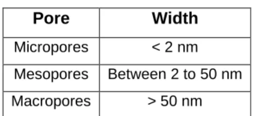
As explained above, activation combustion will increase with increasing temperature, resulting in a higher BET surface area, but as the temperature further increases, the pore wall becomes thinner and begins to break down. Due to the breakdown of the pore wall, the number of pores decreases, the BET surface area and the iodine number also decrease. Within a limited time of 1 hour, micropores begin to change into macropores and cause a decrease in BET surface area and iodine number.
Pore volume can be controlled by controlling the steam flow rate, because high steam flow rate increases burning results in fragile pore structures and results in lower surface area.
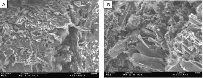
Scanning electron microscope
According to different studies, the steam flow rate has a great influence on yield and surface area of activated carbon. From Table 4.4, according to results there is a 48 yield and maximum surface area of which meets our prerequisite for use as an adsorption material in the cleaning of drinking water, because according to the American Water Works Association (AWWA) surface area greater than 500 be m2/g. However, it is noted that two of the three experiments are below 500 m2/g and show an almost identical surface area.
In this chapter, drying process, heat carrier loop with steel balls, recovery of hot pyrolysis product and activation of biochar will be discussed and explained.
Pre-treatment of biomass
In this work, optimized design concept of pyrolysis plant will be discussed with different required and beneficial changes. In this work, optimized pyrolysis plant can be divided into six units which can be seen in Figure 5.1. In this work, waste heat in the form of flue gas will be used as a drying medium.
Mostly the flue gas was taken from the plant or separately generated in the flue gas burner, and in this work, the exhaust gas (flue gas) will be used for drying after preheating the air, as shown in Figure 5.4.
Dryers
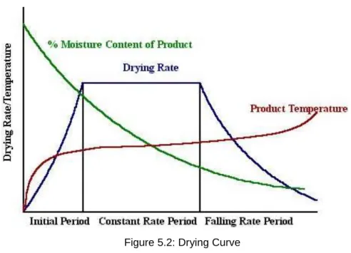
- Stages of drying or drying curve
- Dryer types
- Fire or explosion risk
- Environmental control
Because by drying quickly, we can reduce the time of hot flue gas contact with biomass which helps to reduce the fire risk. Most dryers can be operated at much higher temperatures because the evaporating water vapor keeps the biomass surface temperature lower than flue gas temperature. One safeguard used in most air or flue gas dryers is to maintain a low oxygen concentration in the dryer.
Flue gas dryers typically operate at higher temperatures than air dryers, due to the lower oxygen content of the gas.
Heat carrier loop
The hot pyrolysis products have a temperature of 500 C after leaving the reactor, when pyrolysis products enter the first stage of three-step recycling process, it contains cyclone which removes most carbon particles. The coal fraction is cooled to 120C in a heat exchanger so that waste heat can be used to convert water into saturated steam which will be further used in the production of activated carbon (physical activation). From charcoal particles, we can use waste heat energy which is 31.81 kW, which can be used in the production of saturated steam for physical activation process.
In the final phase, products are cooled in a gas cooler to 80 C to separate condensate and water.
![Figure 5.4: Flow sheet of heat carrier loop with heat carrier steel balls [2]](https://thumb-eu.123doks.com/thumbv2/123dok_br/19675428.0/56.892.111.770.106.666/figure-flow-sheet-heat-carrier-carrier-steel-balls.webp)
Activation of biochar
The physically activated carbon was produced using steam and promising parameters were used in biochar activation. A scanning electron microscope was used to determine the surface morphology of activated carbon produced by chemical and physical activation. In summary, highly active powdered activated carbon was prepared, developed, and characterized from demineralized wheat straw powder biochar precursor by chemical activation.
This work aimed to find alternative use of biochar on industrial application and production of activated carbon.

Recommendation for further research
Ayucitra, "Carbon activated carbon obtained from vacuum pyrolysis of teak sawdust: development and pore structure characterization." Bioresour. Graham, "Study of Physical and Chemical Properties of Activated Carbon Made from Sewage Sludge," Waste Management, Vol. Duangdao, "Preparation and Characterization of Activated Carbon from Pyrolysis of Physic Nut (Jatropha curcas L.) Waste," Energy Fuels, vol.
Hsu, “Preparation of activated carbon from bituminous coal by phosphoric acid activation,” Carbon N. Miyazaki, “Development of KOH activated carbon with high surface area and its application in drinking water treatment,” Carbon N. Aguilar-Pliego, “Chemical activation of Quercus agrifolia char using KOH: Evidence for the presence of cyanide,” Microporous Mesoporous Mater., vol. http://www.en.desotec.pl/p/24/Impregnated-Carbon. Characterization and application of activated carbon produced by activation of H3PO4 and water vapor,” Fuel Process. Diamadopoulos, "Production of activated carbon from sugarcane and rice husks by a one-step chemical activation method at low retention times.", Bioresour.
![Table 2.1: Comparison of product yields for Fast and slow pyrolysis (wt. dry) as reviewed by [4]](https://thumb-eu.123doks.com/thumbv2/123dok_br/19675428.0/18.892.106.783.356.493/table-comparison-product-yields-fast-slow-pyrolysis-reviewed.webp)
![Table 2.4: The MCL (maximum contaminant level) standards, for those heavy metals established by USEPA (US environmental protection agency) [45].](https://thumb-eu.123doks.com/thumbv2/123dok_br/19675428.0/29.892.120.776.221.494/table-maximum-contaminant-standards-metals-established-environmental-protection.webp)
![Figure 2.2: Arsenic affected countries in (red) of the world, [46]](https://thumb-eu.123doks.com/thumbv2/123dok_br/19675428.0/29.892.235.583.766.949/figure-2-arsenic-affected-countries-red-world-46.webp)