It is my great pleasure to acknowledge a sense of gratitude to all the people present in the Laboratory of Applied Mechanical Design (LAMD) with whom I learned during these five months. After the design in the Computer-Aided Design (CAD) software, the drawings of the mechanism were delivered to the workshops responsible for the manufacture of the new mechanism. After comparison with the Computational Fluid Dynamics (CFD) results, it was possible to conclude that the new mechanism allowed an absolute average error reduction in the IGV's alignment of 30.75% compared to the results obtained for the automated gear mechanism.
Introduction
- Motivation
- Project Overview
- Objective
- Thesis Outline
The fifth chapter deals with the methodology involved in choosing the final solution. This includes presenting the constraints and requirements involved in designing the new mechanism. The new mechanism's design chapter includes the presentation of the entire process involved in the design and manufacture of the final mechanism.
Background
IGVs in Compressors
A centrifugal compressor consists of the following four main components [5]: inlet, impeller, diffuser and volume (see figure 5a). It is on this component of the centrifugal compressor that IGVs can be installed, to redirect the inlet flow. Volute: The volute absorbs the flow by redirecting it in the tangential direction and sends it to the compressor outlet pipe.

IGV Theory
By using IGVs, the absolute velocity of the fluid at the leading edge of the impeller may differ angularly. In this equation, 𝑐1 and 𝑐2 are the absolute velocities of the fluid at the inlet and outlet, respectively. The second and third terms describe the deceleration of the impeller, depending on the angles and the angle of the inlet flow.

Guide Vane Mechanisms
- Guide vane air foils
- Control mechanism
As in Pillet's previous model [9], it is essential to note the degree of application. This happens due to the lack of interaction between the various moving parts of the system. In this sense, one of the disadvantages of the mechanisms described in the previous sections is solved.
![Figure 9:NACA 0012 Airfoil with its lift and drag coefficient curves ( source:[9])](https://thumb-eu.123doks.com/thumbv2/123dok_br/19767950.0/27.892.125.740.598.959/figure-naca-0012-airfoil-lift-coefficient-curves-source.webp)
Experimental Investigation
Description of the setup
Experiment conditions
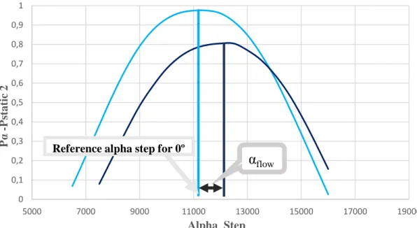
In this test, the position of the probe relative to the Rp axis remained constant at the origin detected in the previous test. The accuracy of the measurement is related to how the second-order function approximates the results (figure 18). In this regard, the most important variable in the results is the relative position of the IGVs to the probe, which is reflected in the angle β illustrated in Figure 20.

CFD results
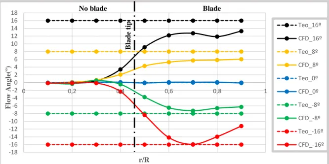
It should be noted that the results from this type of test are independent of the Reynolds number insofar as it is present in the subsonic regime (Mach number < 0.3, where incompressible equations can be used). Taking the theoretical values of the angle as a reference, αTeo, through equation (2) the mean absolute deviation, dm, can be calculated in the difference between the theoretical values, 𝛼𝑇𝑒𝑜, and the CFD values, 𝛼𝐶𝐷.𝐹 It should be noted that in calculating the CFD deviations from the theoretical value, only the radial positions reachable by the IGVs in the streamwise direction were used, because the IGVs do not sufficiently influence the center positions (i.e., r/R [0;0, 45]) in the streamwise direction.
Mechanisms Analysis
Automated Mechanism
- Description of mechanism
- Key elements and error sources
- Experiment testing with the mechanism
- Analysis Conclusions
Since the operating speed is not a requirement of the design (blade angle adjustment), it can be assumed that the stepper motor can operate in the start/stop region (see figure 25). In the case of this application, it was used to reproduce the gear range of the actual automatic system as closely as possible. Fix one of the gears in the train (preferably the crown gear instead of bevel gear);.
In the first test, the backlash measurement of the system was performed without the use of springs to preload the model. This would have significantly increased the costs of the system's steering mechanism and was not realized. In a study by Schreiber [25], the uncertainty associated with the use of this part in the calibration of the automated mechanism was quantified.
From these results, it can be seen that the calibrator plays a vital role in the accuracy of the system. In the experimental evaluation of the automated gear mechanism, the results of Aeschenbacher [1] were used. From the data, it can be seen that the current automated mechanism cannot accurately control the angle of the blade.
Most of the system error comes from the gear train and the system calibration tool;.

Manual Mechanism
- Description of mechanism
- Key elements and error sources
- Experiment testing with the mechanism
- Conclusion of the analysis
The present recordings serve as a reference for the operator when the manual adjustment of the angle is carried out and as such this is a part that must be carried out with good precision. Due to the small scale of the system, the foil present in IGVs must also be small scale. The distance on the z-axis where the operator is from the center of the scale, W.
Because the goniometer is small-scale, most system errors are likely to be operator-sourced. This factor is crucial because if an automatic mechanism is designed, it can curb this contribution to the final error of the new system. The tests were used to assess the skills related to the accuracy of the manual mechanism.
The manual mechanism still does not allow full precision control of the angle of the foils; The graph shown in Figure 46 shows the average angle adjustment error as a function of radial position. Taking the CFD results of the angle, αCFD, as a reference, the mean deviation, dm, can be calculated as the difference between the results of the manual mechanism, 𝛼𝑚𝑎𝑛, and the CFD through Equation 12.
With these values, an average system error can be established in the correct blade angle adjustment that will serve as a measure of the manual accuracy of the system.

Solution Finding
- Requirements
- Constraints
- Methodology in design choice
- Choice of Final Concept
- Lever mechanism
- Direct Drive mechanism
- Conclusion
Due to the small scale of the system, even the manufacturing tolerances become relevant to the accuracy of the system. In the selection of the final concept, the last 2 concepts considered for the control of the IGVs angle are presented. The design of these solutions was the final step in choosing the final concept.
In the final selection of the concept, the two most suitable designs for manufacture and assembly were analyzed. Manufacturing tolerances for the parts connecting the linear actuator to the blades (critical in the calibration task);. The choice of the final solution is a compromise between the accuracy and the cost of the system.
In this system, there are six stepper motors responsible for controlling the position of the blade. In this way, the maximum error in the accuracy of the mechanism in adjusting the angle of the blade is 0.10032º. Manual system Automated system levers mechanism Direct drive mechanism Accuracy of blade adjustment depends on:.
Control unit: This criterion refers to the complexity of the mechanism's control system.

New IGV Mechanism Design
- Mechanical Design
- Structural analysis to the vanes
- O-ring choice
- Sizing of the stepper motor
- Mechanism manufacturing
- Assembly of the mechanism
- Control of the mechanism
When designing or checking a component, the safety factor of the design must first be determined. The accuracy of the stress analysis and the collected experimental data is good (the value of the total channel pressure is known); Elements of the linear tetrahedron type (TE4 - four-node iso-parametric solid element) were used in this simulation [30].
When designing the chosen solution, one of the main requirements is that the module must be gas-tight. Tightness is reflected in the ratio of the amount of deformation applied to the ring. It is quantified by the percentage of the cross-sectional thickness in the free state.
The chosen dimensions can be seen in the drawing of the NACA shaft shown in Appendix A.2. In the case of the stepper motor, the situation will arise when the intention is to adjust the angle with the fluid flow caused by the fan. For the final calculation of the torque required by the system for each stepper motor, it is necessary to evaluate the frictional resistance between the moving parts of the mechanism.
The performance of the mechanism's electronic components depends on the selected operating parameters.
New Mechanism Test Experiments
Due to time constraints and problems with the test bench, the mechanism could not be tested for -16°. For the same reason, the calculated parameters for the direct steering mechanism are based on a smaller sample of data. Based on the results obtained, it can be verified that the new mechanism allows reducing the deviation with the CFD results regarding the blade angle adjustment, compared to the adjustment made by the automated gear mechanism.
For an adjustment of -8º, the error was reduced by 25% by using the direct steering mechanism (table 26). For a setting of +8º, the reduction in deflection is even more significant when comparing the direct drive mechanism with the automated gear mechanism, reaching 72%. In an overall analysis, it was concluded that the new mechanism allowed an absolute reduction of the average error in the adjustment of IGVs of 30.75%, compared to the results obtained for the automated gear mechanism.
In terms of comparing the new design with the manual mechanism, the results are similar for the angles tested.

Conclusions
Achievements
Future work
Finally, to be able to design future centrifugal compressors using the new mechanism, the experimental setup must be improved in order to achieve repeatability whenever the mechanism is changed. A suggestion would be to fix the 3 points marked in figure 87 by creating a specific table. In this way, the relative position of the 3 points would remain unchanged, and the performance of the test cycles would be less time-consuming and more efficient.

Available: https://www.kggear.co.jp/en/wp-content/themes/bizvektor-global-edition/pdf/TechnicalData_KGSTOCKGEARS.pdf.
Annex
- KISSsoft Procedure Analysis
- Technical Drawings
- Technical data of the motor, controller and arduíno
- Arduíno Control Routine
- Procedure to place baldes (automated part)
- Procedure to run the experiment (after placing blade angle)
Datum references: A → Center axis of the vanned shaft B → Surface that sits on the intake pipe. Cylinderity: The outer surface of the cylinder should be between two coaxial cylinders 0.02 mm apart. Symmetry: The axis of the hole into which the calibrator will enter must be between two parallel lines spaced 0.01 mm apart and positioned symmetrically with respect to the A axis.
B → Top surface of the housing that connects to the inlet pipe C → Axis of lateral holes where the vane shaft passes. Geometric tolerances used. Parallelism: The surface of the housing that sits on the cochlea must be between two parallel surfaces, 0.01 mm apart. Cylinderity: The inner surface of the cylinder should be between two coaxial cylinders 0.01 mm apart.
Perpendicular: The axis of the center hole must be included between two parallel lines, which are 0.02 m apart. These two lines are perpendicular to the axis that delineate the outer surface of the workpiece. Flatness: The outer surface of the part must be enclosed between two parallel planes that are 0.02 mm apart.
Set the potentiometer of the controller to the desired step angle of the stepper motor (do not exceed level 4, so as not to burn the motors);
![Figure 6: Compressor map representing how the impeller stalling is influenced by IGVs (source: [6])](https://thumb-eu.123doks.com/thumbv2/123dok_br/19767950.0/24.892.240.629.762.1088/figure-compressor-representing-impeller-stalling-influenced-igvs-source.webp)
![Figure 10:Joints (red mark) present in diferentes lever guide vane mechanisms: a) LAMD b) (source: [11] ) c) Piller Blowers&Compressors (source: [12])](https://thumb-eu.123doks.com/thumbv2/123dok_br/19767950.0/29.892.216.632.101.515/figure-joints-present-diferentes-mechanisms-piller-blowers-compressors.webp)

![Figure 25: Generic example of a Nema stepper motor torque vs speed chart (source: [18])](https://thumb-eu.123doks.com/thumbv2/123dok_br/19767950.0/40.892.202.695.852.1109/figure-generic-example-nema-stepper-motor-torque-source.webp)
![Figure 28:Gear train used in automated mechanism (Gears from Nozag) (source: [22])](https://thumb-eu.123doks.com/thumbv2/123dok_br/19767950.0/43.892.124.723.808.1080/figure-gear-train-automated-mechanism-gears-nozag-source.webp)

