Thanks to my sister Daniela and my brother Daniel for all the support they gave me when I needed it most. Finally, to all my family and friends, thank you for helping me reach this milestone in my life.
Motivation
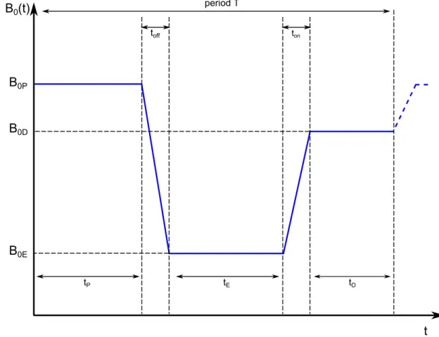
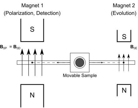
After that, the magnetic field is reduced to a lower B0E value that is applied for a timeE. The field is then switched to a stronger magnetic field B0D and finally the magnetic field returns to the initial value B0P.
State of The Art
This means that the power supply of an FFC-NMR spectrometer requires a control system that guarantees steady and stable currents during tp,teandtd and regulated transitions of the current between these steady periods of the cycle. This embedded system will replace some of the analog technology currently used in the power supply control system.
Evolution)
Thesis Outline
After a brief presentation of the motivation and state of the art in Chapter 1, Chapter 2 presents an introduction to NMR and Fast Field Cycle NMR techniques. system are presented in Chapter 6.
NMR Relaxometry Theory
- Relaxation Time Constants
- The Bloch Equations
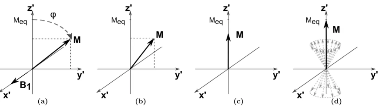
- Radio frequency pulses and FID
These mechanisms are related to the evolution of the different components of the net macroscopic magnetization under the relaxation process. The behavior of the net magnetization during the relaxation process is well described by Bloche equations 2.10.

Fast Field Cycling NMR
- T 1 Measurement
- Signal Sensitivity in NMR
- Field-Cycling Requirements
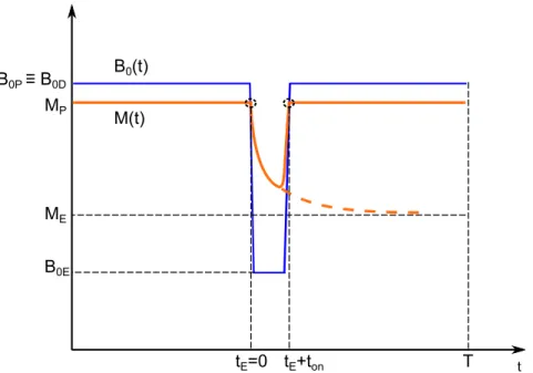
Proper integration gives the behavior of the longitudinal component of the net magnetization through outtE. 2.15). FID detection is done exactly as in the case of conventional relaxometry.

Physical Properties of the Power Supply System
The outputuc(t) is the result of the sum of two correction terms:. 3.4) whereP is the proportional gain,TI is the integral time and. It is able to produce fast conversion of the magnetic field [14] This project aims to develop a digital PID controller that can replace the analog version. The main purpose is to make the control of the relaxation meter power supply more flexible.
The implementation of a digital controller will make it possible to stretch the number of alternatives in terms of the Fast Field Cycling specifications. In the first instance, variable switching times and the application of different field ranges are two of the most promising improvements that will be possible with a digital controller and are much more difficult (or even impractical) to implement in the analog version.

Discrete PID control
Thus, in terms of technical realization, transition times in the order of milliseconds (≈ 3 ms) are acceptable for most soft materials. To achieve a switching time in the order of milliseconds in an upward transition, the control electronics transfer the IGBT transistor to saturation and during this transition the magnetic current is given by. 3.3) By using the auxiliary power supply (Uaux>> U0) during the upward transition, a greater rate of current change is achieved, making it possible to reach the high current level within milliseconds.
An attractive alternative form of the PID controller can be found by shifting equation (3.9) to obtain u(tk−1). 3.11) Equation (3.11) is the speed algorithm for the PID controller. The PID speed algorithm can be rewritten in a most general and flexible form, treating control parameters as simple gains:
Digital Control System
dsPIC DSC family devices include a DSP engine for performing Multiply-Accumulate (MAC) class operations and various on-chip peripheral components. The dsPICDEMTM2 Development Board, to which dsPIC is connected, is a development and evaluation tool that was used to create and implement the embedded control application (3.3). The board allows easy connection to an MPLABR ICD 2 in-circuit debugger, which is used for debugging and programming purposes.
Both dsPICDEM and ICD 2 are prototyping tools that help implement the device, allowing the dsPIC to be connected and programmed. For example, an analog-to-digital converter is used to obtain the output voltage of a Hall sensor.

Digital Controller
Low-pass Filter
Sensor
IGBT Gate
General Configurations
- Clock Source and Timers Configuration
- Output Compare Module: Pulse Width Modulation Output Signal
- A/D Converter Configuration
- Change Notification Pins’ Configuration
- Interrupt Service Routines
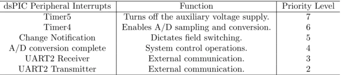
Like most of the dsPIC on-chip peripherals, each timer module has an Interrupt Service Routine (ISR) associated with it. For a desired frequency of the timer interrupts (or in the case of timer 2, for the PWM frequency), the Timer Period Register value (PRx) can be determined by equation (4.2). 22] [23] In this application, this module will be used to generate the output PWM signal from the control system.
The manipulated variable is the duty cycle of the PWM signal, and this module will be used as a digital-to-analog converter, using a low-pass filter to remove high-frequency components, as previously described. According to equation (4.3), to meet (at least) the resolution of the receiving signal, which corresponds to the resolution of the A/D Converter of 12 bits, the maximum frequency of the PWM signal is 28.8 kHz, with a clock source in MHz. .

PID Control Algorithm
- Implementation
For example, when an A/D conversion is complete, a signal is sent to the processor indicating that this event occurred, requiring an interruption of the current code being executed by the processor. It is clear that u(tk) depends on the previous value u(tk−1) and on the values of the error function for instantstk,tk−1 andtk−2. Each data structure is used in the control calculations at different stages of the control cycle.
One PID controller is used to adjust the PWM Duty Cycle for the upward field transition and the other for the downward transition. PID control calculations should be performed after an A/D conversion of the Hall sensor signal is complete.
Description of the Control Operation Sequence
- Transition to High Polarization Magnetic Field
- High Field Steady State
- Transition to Low Relaxation Magnetic Field
- Low Field Steady State
- Time Sequence of the Control Operation
If y = 1, the result of the A/D conversion is compared with a reference value corresponding to a high magnetic field. For y=−1, the result of the A/D conversion is compared with a reference value corresponding to a low magnetic field. PID control of the IGBT voltage gate starts when the control error is less than 2.
From the moment of interruption of the high voltage supply, the control action is the result of the PID algorithm (Figure 4.5. In the following sections, some components of the configuration of the developed control system are presented.

Using PWM Output as a Digital-to-Analog Converter
- Low-pass Filters
- Active low-pass filter design
- DAC Output Signal Conditioning Stage
The results obtained in simulation of the step response for the different low-pass filters can be compared in Table 5.2. For filtering PWM waveform in the PWM D/A converter, a third order Bessel low pass filter is implemented. 1 +ωc[C1(R1+R2) + (1−a)R1C2]S+ωc2R1R2C1C2S2 (5.5) The determination of the circuit parameters of the individual filters must be done in such a way that the product of the frequency responses is the third order Bessel low pass filter.
From the simulation results for the third-order Bessel low-pass filter (Table 5.2), the rise time of the designed filter is approximately 0.14 ms, which is below the field up/down switching time required in this application. After the third-order low-pass filter, a conditioning stage is placed to adjust the signal in such a way as to meet the requirements of the plant (IGBT gate).

Anti-Alias Prefilter
- Signal Conditioning Stage
The Hall sensor signal must be adjusted to match the requirements of the processing stage, the dsPIC30F4011 microcontroller. A ratiometric linear sensor (Honeywell r SS94A2D) is used, in which the output signal is directly proportional to the magnetic actuation. This sensor is bidirectional and at zero field the output signal is half of the supply voltage.
A compensation voltage corresponding to the value of the output voltage of the Hall sensor at zero field is added to the output of the prefilter. An inverting amplifier (OA7) is implemented to adjust the output value of this circuit according to the requirements of the dsPIC30F4011 microcontroller.

Experimental Setup
In the following sections, experimental results obtained using the developed digital control system are presented. To validate the implemented digital control of the FFC NMR prototype, experimental results of the field cycle are analyzed. These results are presented in Section 6.2 and compared with the results obtained using the previous solution for the current source control.

Field Cycle Results
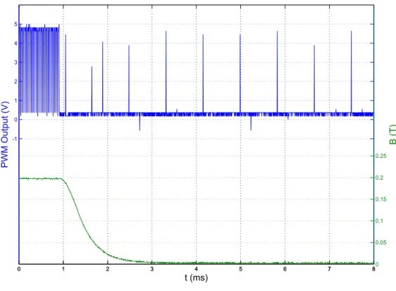
A linear fit of the magnetic field with respect to the input digital reference of the control system is presented in 6.2. Experimental results for upward and downward magnetic field transitions obtained with the developed digital control system are presented in Figures 6.3-6.10. The controller reduces the duty cycle of the PWM signal by applying a low voltage to the IGBT gate.
In general, this corresponds to 85% of the duty cycle obtained once the magnetic relaxation field is reached. Figure 6.12 shows various transitions of the magnetic current and the magnetic field strength.
Spin-Lattice Relaxation Time Measurements
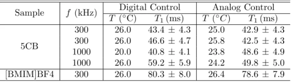
The obtained results prove that, in general terms, the proposed solution can be used as a control system of the energy supply of the relaxometer. The magnetic field was cycled using the digital system to control the magnet current, allowing the exponential decay of the net magnetization in the samples to be observed. Therefore, measurements under the same conditions were performed with the same relaxometer, albeit using the analog power supply control system (measurements shown in B).
The analysis of the spin-lattice relaxation time measurements obtained with each control system shows that the digital control system obtained results in the same order of magnitude as the measurements performed with the analog controller. The results presented here prove that the digital system developed can be used for controlling the power supply of the FFC relaxometer.
Conclusions
Furthermore, the developed digital system was used to modulate the Zeeman field during the measurement of the spin-lattice relaxation time T1 of the 5CB liquid crystal and the [BMIM]BF4 ionic liquid for two different relaxation fields. We observed the exponential decay of the nuclear magnetization and determined the associated time constant for each case.
Future Work
Results suggest that the control system designed in this work can be integrated into the power supply system of the relaxometer. Sebastiao, "Molecular dynamics in a blue phase liquid crystal: a 1h rapid field cycling nmr relaxometry study," Soft Matter, vol. Anoardo, "Application of field cycling nmr relaxometry to the study of ultrasound-induced effects in the molecular dynamics and ordering of mesomorphs materials," C.
Cascais, "Desktop fast-field cycling nuclear magnetic resonance relaxometer," Solid State Nuclear Magnetic Resonance, vol. Ribeiro, "New isolated gate bipolar transistor two-quadrant chopper power supply for a fast field-cycling nuclear magnetic resonance spectrometer."

![Figure 1.4: Scheme of a electronic switch suggested by Redfield at al.[10] (Taken from [7].)](https://thumb-eu.123doks.com/thumbv2/123dok_br/19765788.0/25.892.209.677.105.499/figure-scheme-electronic-switch-suggested-redfield-al-taken.webp)
![Figure 1.5: Control structure of the fast field cycling NMR current source prototype (proposed by Roque et al [14]).](https://thumb-eu.123doks.com/thumbv2/123dok_br/19765788.0/26.892.207.681.108.476/figure-control-structure-cycling-current-source-prototype-proposed.webp)
![Figure 1.6: Architecture of a modern fast field cycling relaxometer (proposed by Roque et al [14]).](https://thumb-eu.123doks.com/thumbv2/123dok_br/19765788.0/26.892.212.679.582.904/figure-architecture-modern-field-cycling-relaxometer-proposed-roque.webp)