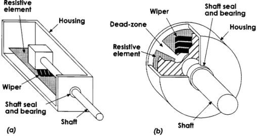
Pots are available in different tapers that determine the shape of the output function. The amplitudes of the output voltages of the secondary coils depend on the position of the core.
Piezoelectric Transducers and Sensors
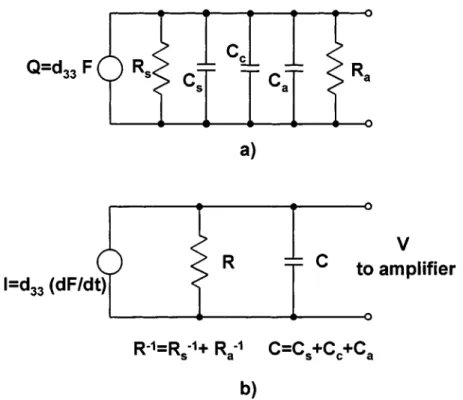
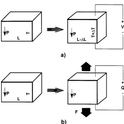
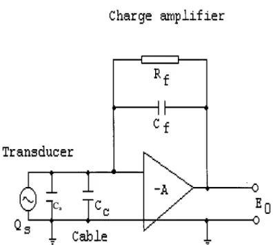
An equivalent circuit must be considered to connect the transducer output voltage to the piezoelectric charge (Figure 6.43(a)). The first example is a ceramic transducer that couples the deformation of the piezoelectric sensor to the output voltage via the direct piezoelectric effect.
Plethysmography Theory
The choice of indicator used to measure volume depends on the application and may be based on temperature, color or radioactivity. The change in volume of the chest is equal to the change in volume of the chest.
Numerical Integration with Imaging
The first section is (randomly) chosen between the first coordinate of the function, and this coordinate plus the step size h. Indicated are the cutting distance h and the scanning angle α with the axis of the probe.

Indicator Dilution Methods
It is also possible to obtain other parameters; for example amplitude and phase of left ventricular ejection. Using the law of conservation of matter, the volume of the lungs can be calculated.

Water Displacement Volumetry
13.24) where Ci is the circumference of the disk at position i with assumed new radius. Consequently, due to its ease of application, the disc model method is the method of choice to measure limb volumes.

Equipment and Experiments
A disc height of 10 cm will be sufficient to measure the bone volume with an accuracy of at least 95%. However, it may be necessary to use a small interdisc section to obtain a higher accuracy, which may be necessary to accurately monitor the edema changes in volume.
Evaluation
One explanation is that blood filling a segment of the body lowers the impedance of that segment. The resonator frequency is inversely proportional to the square root of the volume of air in the resonator.
Introduction
Measurement of Linear Velocity
However, they give a speed relative to the transducer speed at the start of the test. The frequency of these transitions from light to dark is proportional to the speed of the moving target.
Velocity: Angular
After amplification, these signals are demodulated into a DC signal that is proportional to the rotation of the sensor. As shown in Figure 16.16, the magnitude of the differenced signals, a1 and a2, is divided by the distance between the two sensors, l.

Conclusion
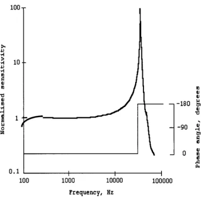
Frequency Range • Sensitivity, Mass and Dynamic Range • Transient Response • Full Scale Range and Overload Capability • Environmental Conditions 17.13 Signal Conditioning. For practical purposes, accelerometers can also be classified as mechanical or electrical, depending on whether the restoring force or other measuring mechanism is based on mechanical properties, (eg on electrical or magnetic forces.
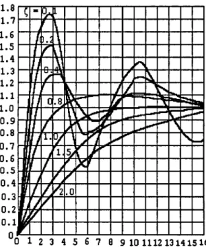
Accelerometer Dynamics: Frequency Response, Damping, Damping Ratio, and Linearity
However, statistical methods and probability theory can be applied to FIGURE 17.2 Logarithmic relationship between acceleration, velocity, and displacement. Therefore, equation 17.5 can be generalized by taking into account the effect of base motion.
Electromechanical Force-Balance (Servo) Accelerometers
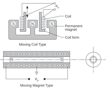
A pickup mechanism detects the displacement of the coil under FIGURE 17.4 Unit step-time responses of a second-order system with various damping ratios. Displacement of the coil due to acceleration causes an electrical potential in the coil to be sensed and processed.
Piezoelectric Accelerometers
Under steady state conditions, motor speed is a measure of the acceleration acting on the instrument. The upper frequency of the accelerometer is limited by the resonance of the PZT crystal.
Piezoresistive Accelerometers
Differential-Capacitance Accelerometers
Denoting the gap size for zero acceleration as h0, the value of h in the presence of acceleration a can be written as:. A commonly used example of a capacitive-type accelerometer is based on a thin membrane with helical bends that provide the spring, proof mass, and movable plate required for the differential capacitor, as shown in Fig. 17.12.

Strain-Gage Accelerometers
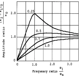
Seismic Accelerometers
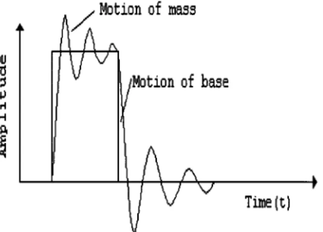
If the seismic instrument has a low natural frequency and a displacement sensor is used to measure the relative motion z, then the output is proportional to the displacement of the transducer case. Electrical resistivity strain gauges are also used for displacement sensing of the seismic mass as shown in Figure 17.15.
Inertial Types, Cantilever, and Suspended-Mass Configuration
The beam length is adjusted so that the natural frequency is equal to the frequency of the vibrating surface - hence the resonance condition obtained. Shaft speed is proportional to the square root of the local value of the acceleration.

Electrostatic Force Feedback Accelerometers
17.44) Therefore, if the bias potential V1 is held constant and the gain of the control loop is high so that changes in the gap are negligible, the acceleration becomes a linear function of the controller output voltage V2 as:. The main advantages of electrostatic accelerators include extreme mechanical simplicity, low power requirements, lack of inherent sources of hysteresis errors, zero temperature coefficients, and ease of shielding from stray fields.
Microaccelerometers
The dynamic cancellation effect of the DETF design prevents energy loss through the beam ends. The resonant frequency of the system must be much higher than any input acceleration, which limits the measurable range.

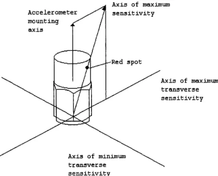
Cross-Axis Sensitivity
Selection, Full-Scale Range, and Overload Capability
The dynamic range of the accelerometer must match the high or low acceleration levels of the measured objects. Bubbles are caused by high-frequency components of the excitation near-resonance frequency that prevent the accelerometer from returning to its steady state.
Signal Conditioning
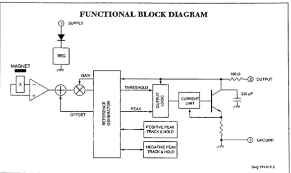
A typical example of a signal conditioning circuit is given in block diagram form in Figure 17.23. This chapter begins by reviewing the basic definitions of strain and the ways in which it can be measured.
Fundamental Definitions of Strain
When the relationship between shear stress and shear stress is linear, the relationship between shear stress and shear stress is the shear modulus G. For the Moiré technique, the stress resolution is a function of the length of the viewing area.

Principles of Operation of Strain Sensors
The output of the bridge is the difference between the voltage at points B and D. Paths ABC and ADC are voltage dividers so that VB and VD are given by equations 22.15a and b Wheatstone bridge signal conditioners are constructed with a means of "balancing" the bridge by adjusting the ratio of the resistors so that the bridge output is initially zero. The center of the circle is labeled C and the radius R. The cardinal directions correspond to zero shear stress.

General Considerations
Hooke’s Law
The aforementioned methods used for measuring forces yield a variety of designs of measuring equipment. The challenge associated with the task of measuring forces lies primarily in sensor design. The means by which the force can be converted into a workable signal form (such as electronic signals or graduated displacements).

Force Sensors
23.7) The grid configuration of resistance strain gauges made of metal foil is formed by a photoetching process. 23.12), where d is the charge sensitivity (constant for a given crystal) of the crystal in C/N. A force F causes a change in thickness.
![FIGURE 23.3 Different types of load cells [2].](https://thumb-eu.123doks.com/thumbv2/123dok_br/19471135.0/129.918.227.706.84.345/figure-different-types-of-load-cells.webp)
Introduction
The Origins of Biopotentials
Movement of the eyeballs within the conductive contents of the skull changes the electrical potentials. Placing the electrode in the vicinity of the eyes (on either side of the eyes on the temples or above and below the eyes) picks up the potentials associated with eye movements called EOGs.

Biopotentials
This extended lead system allows localization of diagnostic features, such as epileptic seizures, near the electrode [18]. Similarly, saccades inherent in eye movements and eyelid blinking can cause changes in the EOG signal.

The Principles of Biopotential Measurements
Nevertheless, EOG signals can be clinically useful in acute studies of human disorders, and therefore careful acquisition of the signal followed by appropriate analysis is used to interpret the EOG potentials. A thorough effort is needed to minimize the noise and interference by improving the electrode design and placement and optimizing the amplifier circuit.
Electrodes for Biopotential Recordings
Occasionally, carbon or carbon-impregnated polymer electrodes are also used (although they are mainly used as electrical stimulation electrodes) [20]. For research applications, similar needle or wire electrodes are sometimes connected directly to the heart muscle.
The Biopotential Amplifier
This design results in the desired differential gain distributed over two stages of the amplifier. It also achieves a very high input impedance as a result of the non-inverting amplifier front.
Circuit Enhancements
Electrical isolation limits the possibility of leakage current from the instrument being used to the patient [22]. Therefore, the front of the biopotential instrument must be designed to withstand these high voltages (Figure 74.6f).

Measurement Practices
To eliminate RF interference, filter capacitors should be used at the front end of the amplifier as well as at various stages of the amplifier. The CMRR characteristic of the amplifier is crucial for reducing the common-mode voltage [24].
Conclusions
Electrode leads can be shielded or at least twisted together to reduce induced electromagnetic interference. Finally, the driven right arm design [27] described earlier can optionally be used to further reduce the total voltage and effective interference.
Introduction
Blood pressure values vary significantly over 24 hours according to an individual's activity [1]. Basically, three factors, namely, the diameter of the arteries, the cardiac output and the condition or quantity of the blood, are mainly responsible for the level of blood pressure.
Measurement Techniques
Unfortunately, elevated blood pressure does not ensure proper tissue perfusion, and in some cases, such as certain types of shock, blood pressure may appear adequate when peripheral tissue perfusion has almost stopped. This system, however, greatly affects other organs in the body.
Indirect Blood Pressure Measurement
The AHA has published six editions of the AHA recommendations for indirect measurement of arterial blood pressure. Systolic and diastolic blood pressure were determined by cuff pressure, with the amplitude of the oscillation a fixed fraction of the maximum.

Direct Blood Pressure Measurement
Using neural network training and processing, subtle features and nonlinear relationships of the oscillometric envelope have been modeled. The sensor must be zeroed at heart level to eliminate hydrostatic errors [73].
Reproducibility, Accuracy, and Reliability Issues and Recommendations for Corrective Measures
Less often, entering a vein requires a "cutdown," direct exposure of the vein through a skin incision. Although pressure sensors can be placed at the tip of the catheter, this presents a calibration problem if it remains in place and a clot forms near the tip of the catheter, dampening the pressure signal.
Blood Pressure Impact, Challenge, and Future
Littler et al., The British Hypertension Society Protocol for the Evaluation of Blood Pressure Monitors, J. Millar-Craig, Technical and Clinical Evaluation of the Medilog ABP Non-Invasive Blood Pressure Monitor, J.

Doppler Measurements
The depth is of course determined by the delay time and the propagation velocity in the tissue. The amplitude of the same signal is proportional to the number of moving scatterers in the tissue volume.

Indicator Dilution Methods
Thus, only the amount of added indicator and the time integral of the downstream concentration, assuming proper mixing, need to be known in order to calculate the flow, i.e. cardiac output. A thermal dilution catheter is placed with the injection outlet in the right atrium of the heart and with a temperature sensor in the pulmonary artery (Bronzino [6] and Weissel et al. [7]).

Plethysmography
The first reports on the successful application of the principle were published in the mid-1930s by Molitor and Kniazuk [11]. A signal modulated by the attenuation or scattering of light in the blood volume can be recorded.

Radioisotopes
If the tissue is permeated uniformly and constantly, the activity of the isotope decays monoexponentially over time. The trauma caused by the injection of the isotope into the tissue severely disturbs the flow, as shown by Holloway [17] and Sejrsen [18].
Thermal Convection Probes
The temperature difference between the two rings is a measure of the blood flow under the probe. The kilogram is the unit of mass: it is equal to the mass of the international prototype of the kilogram (3rd CGPM, (1901).