59 5.7 The effect of changing the angle of attack of the main wing and the lower wing from visualization i. 91 A.3 Effect of changing the angle of attack of the main wing and the lower wing by visualization i.
Nomenclature
Glossary
MISQP Mixed-Integer Sequential Quadratic Programming is an optimization solution that handles dense mixed-integer nonlinear programming problems by a modified sequential quadratic programming method. NLPQL Nonlinear Programming of Quadratic Lagrangian is an optimization gradient based single objective optimization that solves smooth nonlinear programming problems by a sequential quadratic programming method.
Introduction
- Motivation
- Rear Wing Optimal Design
- Design Considerations
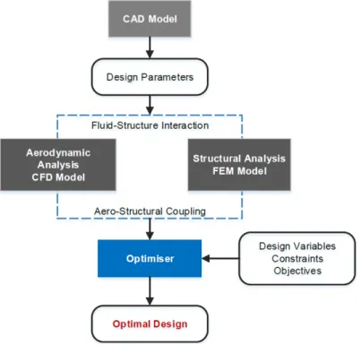
- Multidisciplinary Design Analysis and Optimisation Framework
- Thesis Objectives
- Dissertation Structure
One good example would be the turn of the rear wing over its span length. Nevertheless, the assembly of a car's rear wing these days allows the fine-tuning of the angle of attack according to the track characteristics.

Automotive Aerodynamics
History of Aerodynamics in Performance Cars Design
- The Impact of Motorsport Aerodynamics on Production Cars
The McLaren F1 team introduced carbon fiber and Kevlar into the construction of the chassis, wings and body, making the prototypes and F1 cars lighter and stronger. At the end of the 1980s, the so-called "earth effect era" came to an end for safety reasons [13].
![Figure 2.1: Introduction of ground effect by F1 Lotus team in 1977 [11].](https://thumb-eu.123doks.com/thumbv2/123dok_br/19768333.0/32.892.176.706.179.353/figure-introduction-ground-effect-f1-lotus-team-1977.webp)
Performance Cars Aerodynamic Devices
- Vehicle’s Front-End
- Vehicle’s Under-body
- Vehicle’s Back-End
It can be found in different parts of the vehicle and has a strong impact on the underbody airflow [14]. The fast air flowing from the front splitter is further increased in velocity at the converging section of the underbody tunnels (nozzle), which reaches the lowest pressure at the narrowest flow passage (throat), which creates.
![Figure 2.4: Downforce and drag coefficient versus ground clearance for an inverted LS(1)-0413 airfoil [15]](https://thumb-eu.123doks.com/thumbv2/123dok_br/19768333.0/34.892.254.624.164.481/figure-downforce-coefficient-versus-ground-clearance-inverted-airfoil.webp)
Methods used for Evaluating Automotive Performance
- Numerical Simulations
- Wind Tunnel Testing
- Road and Track Testing
Such modeling techniques have an important effect on the quality of the numerical solution, especially for the prediction of flow separation (in smooth curved surfaces) and for the transition from laminar to turbulent flow at high Reynolds numbers [14]. They compared various solution methods with wind tunnel results for the flow over generic aircraft configurations, particularly predicting the incremental drag associated with the nacelle/pylon installation.
Theoretical Background
Aerodynamic Theory
- Governing Equations of Fluid Flow
- Turbulent Flows and Turbulence Modelling
The boundary layer is the fluid layer in the immediate vicinity of the wall where the effects of viscosity are significant. In the outer layer, called the fully turbulent region (orlog-law region), turbulence plays a major role, and the region between the viscous substrate and the fully turbulent layer is called the buffer layer, where both molecular viscosity and turbulence effects cannot be neglected. For the flow over airfoils or wings, a result of the use of such models is the overprediction of the drag [32].
![Figure 3.1: Subdivisions of the flow near-wall region [31].](https://thumb-eu.123doks.com/thumbv2/123dok_br/19768333.0/44.892.246.640.113.385/figure-3-subdivisions-flow-near-wall-region-31.webp)
Structures Theory
- Governing Equations of Solid Structure
- First-Order Deformation Theory
In the analysis of thin and layered composite structures, shell elements are widely used to keep the computational effort reasonable [42] and in-plane stresses and transverse shear stresses can be predicted with good accuracy using shells based on the First Order Shear Deformation Theory ( FSDT ), described by [4]. Under the same assumptions and limitations as in the classical laminate theory, according to the displacement field of the first-order theory is of the form. With the above relationships, stresses and displacements in laminated composites subjected to in-plane tensile or bending loads can be determined for each material type in the stacking sequence.
Fluid-Structure Interaction (FSI)
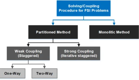
- Monolithic and Partitioned Methods
The fluid-solid interface is processed synchronously, which requires a conformal mesh (matching node positions) between the fluid and solid meshes. With two-way coupling, the solution data is always transferred both ways at the liquid-solid interface. During the first time step, a converged solution of the fluid side is required to provide the forces acting on the body.
Multidisciplinary Design Analysis and Optimisation (MDAO)
- MDAO Architectures
- Numerical Optimisation Techniques
However, an improved estimate of the global optimum can be achieved if several search procedures are performed, from different starting points [51]. First, initial approximations are obtained by analyzing the system response for defined combinations of design points, and then, the approximation model is used within the optimization cycle. In order to fulfill the objectives proposed for this thesis, the appropriate computational tools had to be chosen, taking into account the available computational resources and the synergy of the different disciplines involved.
![Figure 3.4: Illustration of Response Surface Optimisation Methodology [51].](https://thumb-eu.123doks.com/thumbv2/123dok_br/19768333.0/52.892.151.756.312.535/figure-3-illustration-response-surface-optimisation-methodology-51.webp)
MDAO in ANSYS R Workbench 14.5
This chapter provides a description of such tools (numerical models) used to perform the CFD, CSM, FSI and optimization analyses, as well as the generation and parameterization of CAD geometries, mainly the specific modeling techniques, settings and simplifications adopted regarding both the reliability and quality of the numerical solutions. Both modules F and G are the optimization tools available in ANSYSR, recognizing the assigned input and output parameters in modules A, B, C and D for certain optimization goals, with different optimization tools (direct optimization methods with module F and response surface optimization method with module G).
CAD Model: ANSYS R DesignModeler
CFD Model: ANSYS R Fluent
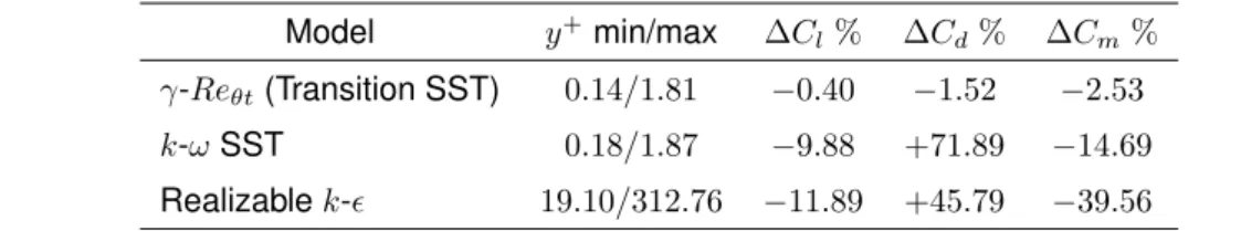
- Model Validation with NACA 4415 Airfoil Two-Dimensional Analyses
- Benzing BE 122-125 Airfoil Three-Dimensional Analyses
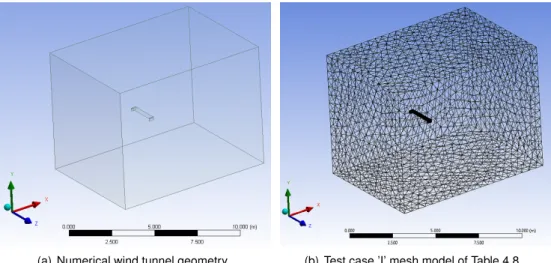
Such conditions are used for the upper and lower limits of the wind tunnel, so that they have no influence on the flow behavior. First, the results regarding the number of distributions for the upper and lower camber lines of the airfoil are shown in Table 4.4. The inflation options are the same as those of two-dimensional test case 'XXIV'. b) Test case 'VI Opt.' with 80 airfoil distribution numbers and 200 spans.
![Table 4.1: Fluid flow reference values and target experimental data obtained from references [61, 62].](https://thumb-eu.123doks.com/thumbv2/123dok_br/19768333.0/55.892.158.732.618.745/table-fluid-reference-values-target-experimental-obtained-references.webp)
CSM Model: ANSYS R Composite PrepPost and Mechanical
- Finite Element Analysis Setup
Optimization analyzes were performed only with the application of the test case 'VI Opt.' considering the minimization of computational effort. The "Mesh I" test case is closest to the CFD mesh (same strategy and value for the number of edges of the partitions), referred to as "random mesh". Regarding the relationship between mesh density (CFD and CSM mesh variations) and imported loads, no relevant differences were found in the calculated mechanical forces, except in the case of the coarser mesh test 'Mesh VI'.

FSI Model: ANSYS R System Coupling
- One-Way versus Two-Way Coupling
As mentioned in Section 4.4, when using one-way one-way coupling (without using system coupling) for non-matching meshes at the fluid-solid interface, the mechanical nodes are calculated by linear interpolation from the surrounding CFD nodes, and such a mapping procedure is not conservative [34, 68]. . Two different mapping methods are commonly used for one-way and two-way FSI problems using system coupling [34, 69]. Therefore, ANSYSR technical support staff recommended that it not be used for unidirectional coupling.
Optimisation Model: ANSYS R Direct Optimisation
That said, the option was to use the goal-driven optimization tool with direct optimization methods that use high-fidelity CFD and FEM codes, demanding accuracy and robustness when performing aerodynamic and structural optimization of rear wing designs. Central difference: increases the accuracy of gradient calculations, but doubles the number of design point estimates;. Forward difference (set option): uses fewer design point estimates, but reduces the accuracy of gradient calculations.
Results
MDAO Design Variables and Functions of Interest
Therefore, the main wing dimensions (chord and span), operating mode (angle of attack), endplate dimensions and the position of the vertical supports are the design variables of interest in the MDAO process. So, besides the aerodynamic downforce generation and drag reduction, the main function of interest is the rear wing efficiency, given by the lift-to-drag ratio (-L/D). Regarding the structural integrity of the rear wings, the failure analysis of the composite layers is also a feature of interest.

CAD Parametric Design
- Airfoil Selection
- Endplate Design
- Vertical Wing Support Design
- Flow Design
- Parameters
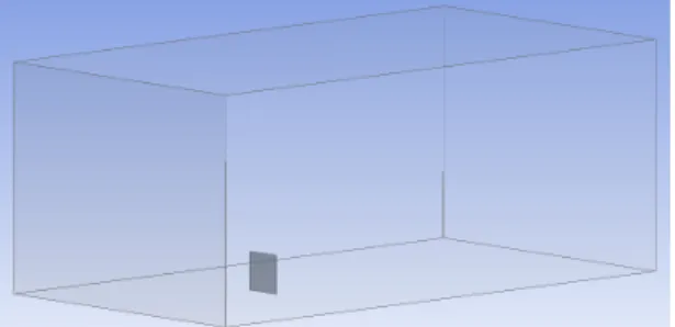
An example of the proposed rear wing baseline in the FluentCFD computational domain can be seen in Figure 5.5 (fluid flow in the x-axis direction). Lower wing position: horizontal and vertical position relative to main wing leading edge line, rear wing only proposed; Profile chord: of the main wings of the traditional and proposed rear wings and also for the lower wings of the proposed version;

Aerodynamic Parametric Studies
- Effect of Horizontal and Vertical Positioning of Lower Wings
- Effect of Chord, Wingspan and Angle of Attack
- Effect of Endplates Dimensions
- Vertical Supports Positioning
Angle of attack: relative to the fluidflowx axis, for the main wings in the traditional and proposed rear wings and also for the lower wings in the proposed design. The performance response of the rear wings to the variation in angle of attack was performed for 1, 5 and 10 degrees. On the other hand, by reducing the support distance (Figure A.4(a) in Appendix A), the wingspan of the lower wings was.

Aerodynamic Optimisation
It was interesting to observe that, for this optimization problem, the algorithm NLPQL progressed to an increase of the profile chord with the reduction of the wing angle of attack. The aim of this problem optimization was to understand how the surface area of the lower wings (given by the vertical support position) affected the efficiency of the design, by increasing/decreasing this distance in combination with increasing/decreasing the main wing profile chord and angle of attack. For this optimization problem, the algorithm NLPQL progressed to an increase of the vertical support distance, with decrease of the main wing airfoil chords and increase of the main wing angle of attack.

One-Way FSI Structural Parametric Studies
- Effect of Material Type
- Effect of Number and Orientation of Composite Plies
For the traditional rear wing this is achieved for 8 layers, either for the proposed rear wing for 16 layers. No significant changes were observed for the failure criteria, with the exception of the Maximum Stress failure criterion. On the other hand, the highest values of the failure criteria calculated for the traditional rear wing were located at the connection between the lower wing side and the vertical struts (front side), as seen in Figure 5.10(b).

One-Way FSI Structural Optimisation
Regarding the progression of the optimization problem, the mass reduction was continuously minimized (a consequence of the reduction in the number of inputs) for a slightly fluctuating increase in the value of the constraint function, as can be seen in Appendix A, Figure A.5. A much smaller reduction in error efficiency compared to the traditional posterior structural optimization problem was also observed. To conclude the structural optimization studies, an additional optimization was performed for the proposed rear wing design to reduce the maximum deformation value.
![Table 5.26: Traditional rear wing structural optimisation results for minimisation of mass, using sets of [(45,90) n ]s for the stacking sequence of Wing Skin/Wing Spars/Endplates.](https://thumb-eu.123doks.com/thumbv2/123dok_br/19768333.0/98.892.129.766.158.282/traditional-structural-optimisation-results-minimisation-stacking-sequence-endplates.webp)
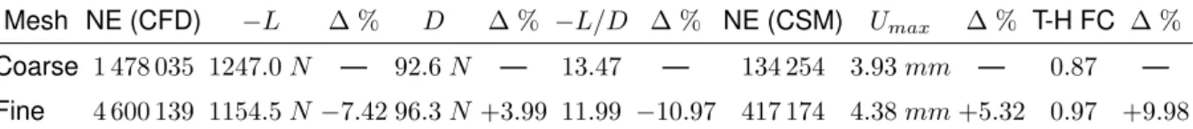
Reduced/Finer Mesh Models and Final Results
For the proposed rear wing design, the increase in the value of the Tsai-Hill failure criterion was such that it exceeded unity (1.04). By increasing the mesh density, not only were the deformations greater in the traditional rear wing design, as the failure efficiency was significantly underpredicted by the reduced mesh model in both designs. Given the range of operating conditions, a traditional rear wing will always be able to achieve lower downforce values (where it is more efficient) compared to the proposed design.
Conclusions
Analyses Conclusions and Recommendations
As for the structural discipline, optimized performance can be obtained through proper shape designs through fluid-structure interaction to obtain minimal mass and deformations. Structural efficiency can be achieved by selecting materials with a high strength-to-weight ratio, such as CFRTP. The effectiveness of the structure should be assessed for critical or extreme operating conditions, where failure performance may be compromised.
Future Work
Again, parametric studies of the structural design variables of interest use the optimization procedure to rapidly achieve optimal structural attributes. For the optimization of aerodynamic and structural disciplines, the application of Sequential Quadratic Programming (SQP) methods, NLQPL and MISQP optimizers respectively for continuous (aerodynamic discipline) and discrete (structural discipline) parameters, proved to be an efficient choice in terms of design improvements and computational time to meet converged solutions.
Bibliography
An experimental study of the aerodynamic interaction between a closed-wheel racing car and its rear wing. Comparison of one-way and two-way coupling methods for numerical analysis of fluid-structure interactions. Comparison of different methods for merging mismatched meshes in fluid-structure interaction calculations.
Appendix A
Data
- Additional Aerodynamic Parametric Studies
- Effect of Wingspan Variation
- Effect of Angle of Attack Variation
- Effect of Endplates Dimensions Variation
- Effect of Vertical Supports Positioning
- One-Way FSI Structural Optimisation
- Final Results and Designs Comparison
Appendix B
Material Properties Data Sheets
![Figure 2.5: Interaction between the rear wing and the car body [21]. [coefficients based on the car reference area; c: chord; α w : wing angle of attack; ∆H: rear wing height from car; ∆x: rear wing backward position from rear deck; A : aspect ratio; β: un](https://thumb-eu.123doks.com/thumbv2/123dok_br/19768333.0/37.892.177.733.115.375/figure-interaction-coefficients-reference-attack-height-backward-position.webp)