This paper was written by Jason Ingham and Kok Choon Voon from the Department of Civil and Environmental Engineering, University of Auckland. The authors wish to acknowledge the role of Standards New Zealand and of the committee members responsible for drafting NZS 4230:2004. The authors would like to thank David Barnard and Mike Cathie for their assistance in formulating the design notes and developing the design examples included in this guide.
Except where permitted by the Copyright Act, no part of this publication may be reproduced, stored in any retrieval system in any form or transmitted by any means without the prior written permission of the New Zealand Concrete Masonry Association Inc.
Background
The latest version of this document has the full title "NZS 4230:2004 Design of reinforced concrete masonry structures". The purpose of this user guide is to provide additional information that explains the rationale for new or amended clauses in the new standard and to show the process by which the new standard is intended to be applied.
Related Standards
Change of Title and Scope
Nature of Commentary
Material Strengths
- Compression Strength f’ m
- Modulus of Elasticity of Masonry, E m
- Ultimate Compression Strain, ε u
- Strength Reduction Factors
This value was somewhat arbitrarily taken to be conservatively less than the comparable value of εu = 0.003 specified in NZS 3101 for the design of concrete structures. Consequently, when using NZS 4230:2004, the ultimate compressive strain of unconfined concrete masonry will be taken as εu = 0.003. There is no measured data to form a basis for adopting strength reduction values other than those used in NZS 3101 for concrete structures, and the adoption of corresponding values will facilitate designers switching between NZS 4230 and NZS 3101.
The values adopted in NZS 4230:2004 are more conservative than those recently prepared by the Joint Masonry Standards Committee2 (consisting of representatives from the American Concrete Institute, the American Society of Civil Engineers and the Masonic Society).
Design Philosophies
Limited Ductile Design
Component Design
Definition of Column
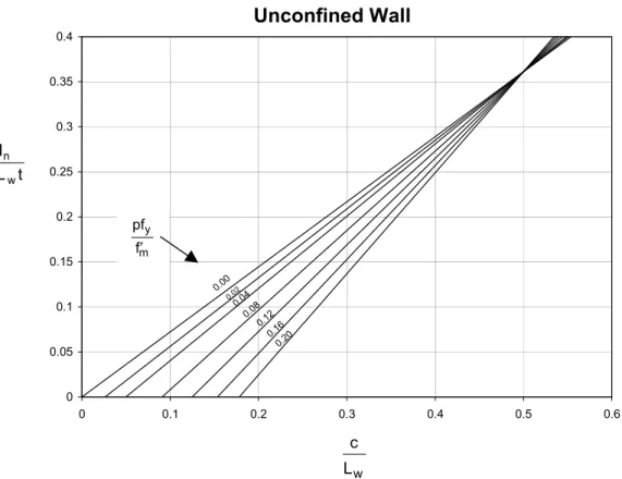
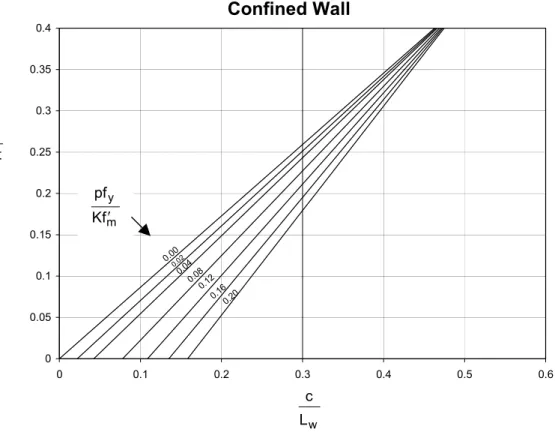
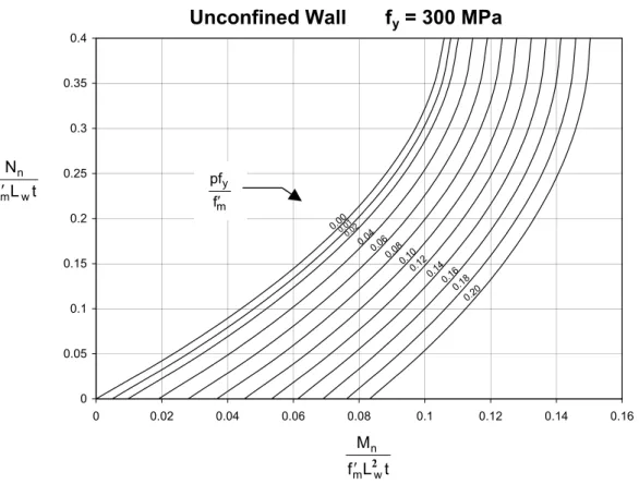
Moment Capacity of Walls
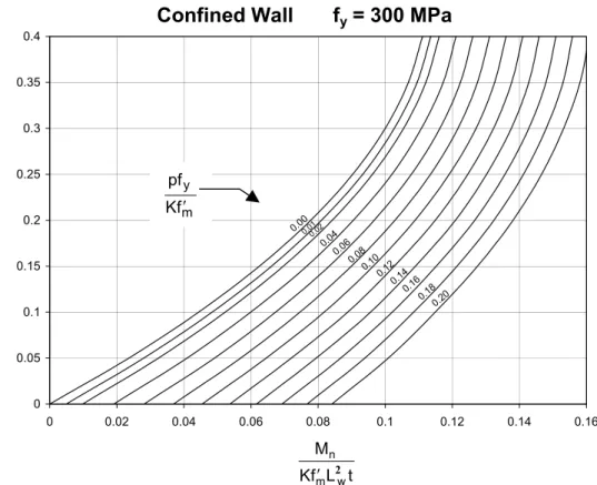
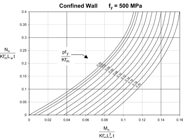
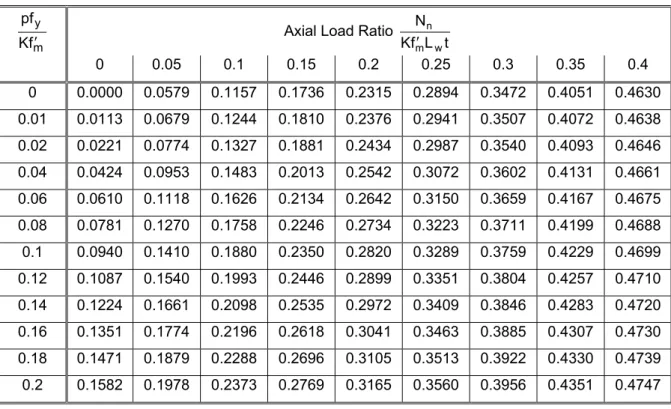
Diagrams constructed from Tables 2 to 5 are also drawn to allow the user to quickly obtain values for pfy/f'm or pfy/Kf'm in relation to the axle load ratio Nn/f'mLwt or Nn/Kf'mLwt and the moment ratio Mn /f'mLw2t or Mn/Kf'mLw2t.
Maximum Bar Diameters
Ductility Considerations
- Neutral Axis Depth
- Curvature Ductility
- Ductility Capacity of Cantilevered Concrete Masonry Walls
- Walls with Openings
The available ductility at this ultimate compressive strain decreases with increasing depth of the compressive zone, expressed as a fraction of the wall length. As shown in Figure 7(a), the maximum curvature malleability is expressed as: where φm is the maximum curvature expected to be achieved or relied upon and φy is the yield curvature. a) Moment curvature relationship (b) First yield curvature (c) Ultimate curvature. The Standard allows the rational analysis developed by Priestley3, 4 as an alternative to determine the available ductility of cantilevered concrete masonry walls.
Where the required increase in f'm cannot be provided, a second alternative is to limit the masonry within critical sections of the wall.
Masonry In-plane Shear Strength
More recent experimental studies conducted in New Zealand and overseas have successfully demonstrated shear strength of reinforced masonry walls significantly in excess of that permitted in NZS 4230:1990. As outlined in Section 10.3.2.2 (Eqn. 10-5), the masonry shear strength must be evaluated as the sum of contributions from individual components, namely masonry (vm), shear reinforcement (vs), and applied axial compressive load (vp). As the shear strength provisions in NZS 4230:2004 are derived from experimental data for masonry walls, and because the new shear strength provisions generated significantly reduced requirements for shear reinforcement, Sections 8.3.11 and 9.3.6 and Eqn. 10.
-9 of NZS should be considered to establish the amount and details of minimum shear reinforcement required in beams and columns. 2003) "Tear Strength of Concrete Masonry Walls", School of Engineering Report No.
Design of Slender Wall
Determine f’ m From Strengths of Grout and Masonry Units
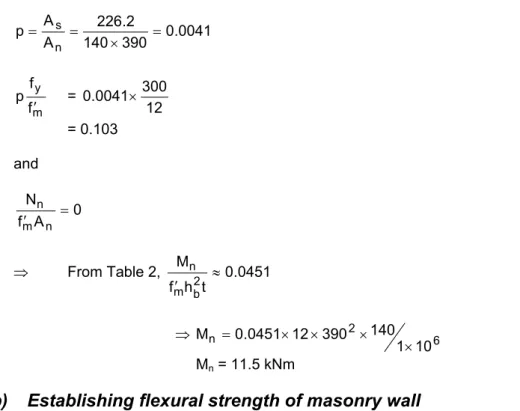
In-plane Flexure
Calculate the nominal flexural strength of the 140 mm wide concrete wall shown in Figure 11.
Out-of-Plane Flexure
Design of Shear Reinforcement
As illustrated in NZS Figure 10.2, it is necessary to calculate the compaction depth a to set tanα. It is essential that the shear reinforcement is adequately anchored at both ends to be fully effective on both sides of any potential trending crack. Although attaching the rod around the vertical end reinforcement in the walls is the best solution for anchoring, it can cause excessive overloading of the end ducts and result in incomplete insertion of the flue.
Consequently, bending the shear reinforcement up or down in the flue is acceptable, especially for walls of small width.
Concrete Masonry Wall Ductility Considerations
Ductile Cantilever Shear Wall
Limited Ductile Wall with Openings
It is assumed that the bars are stiff enough to force the mid-height contraflexure points in the piers. This is because walls of different lengths in the same direction will not have the same yield displacement. This means that the basic assumption of the traditional approach, to distribute the lateral load on the walls in proportion to their stiffness, as a means of obtaining simultaneous yielding of the walls, and hence uniform ductility demand, is impossible to achieve.
The moments and shears in the piers can be found from the method suggested by Paulay7. This design approach assigns lateral force between columns in proportion to the product of element area, An = bwLw, and element length, Lw, rather than the second moment of area of the section, as would result from a stiffness approach, i.e. the column strength must be in proportion to L rather than L being allocated. Consequently, the pier shear forces and moments are as summarized in Tables 9 and Aspects of Drift and Ductile Capacity of Rectangular Cantilever Structural Walls”, Bulletin of NZNSEE, Vol. 1997) "A review of coding for torsional seismic effects in buildings", Bulletin of NZNSEE, Vol. At insertions, the moments in the tension wire on either side of the joint are estimated, taking into account equilibrium requirements, by assuming that the tension wire moment on one side of a joint's center line is equal to the ratio of the lengths of the adjacent span times the spandrel moment on the other side of the joint.
More sophisticated analyzes are probably unsuitable due to deep sections, large joints and the influence of cracks and shear deformations. The axial forces in the piers are found from the shear resultant of the beam (vertical equilibrium), and these are shown in Table 11. The minimum requirements of D12 @ 200 again govern the bending, but the shear reinforcement in the external piers can be reduced to 0.07% of the area gross cross-section of the wall (minimum area of reinforcement required by point 7.3.4.3).
This is also the minimum reinforcement area of 0.07% required by clause 7.3.4.3 of the standard. An estimate of the shear force of the joint can be found by the appropriate slope of the moment gradient through the joint (Paulay and Priestley, 1992). H′b and hc′ are the approximate distance between the lines of action of the flexural compression found in the beams and columns on opposite sides of the joints.
The horizontal displacement is carried by the horizontal component of the diagonal brace across the joint.

Strut-and-tie Design of Wall with Opening
Figures 20(a) and (b) show the strut-and-tie models for the squat wall with openings, corresponding to the lateral seismic forces considered. To ensure that plastic hinges are formed within the vertical members of the 1st floor, the amount of reinforcement in the vertical members of the 2nd and 3rd floors must be sufficient to ensure that these elements do not yield . While the use of strut-and-life analysis is specifically endorsed in Section 7.4.8.1 of the NZS, no advice is given in Section 3.4.7 on an appropriate value of φ to be used in connection with the analysis.
This corresponds to the factor φ used for shear and torsion, which is consistent with the strut-and-tie procedure. Consequently, φ = 0.75 is adopted here for use in column and bond analysis of concrete masonry structure. Note that in the above calculation, it is known that the vertical component of the E-N beam corresponds to the force in the M-N connection.
To avoid the formation of plastic hinges, the amount of reinforcement in the 2nd and 3rd floor vertical elements should be sufficient to ensure that yielding does not occur in these elements. Therefore, the 2nd and 3rd floor vertical members are deliberately designed for 50% higher tensile forces than the design level tensile forces. Therefore, the design of tie K-L will match tie J-K. note that DH16 is the maximum bar size allowed in table 1) For slip F-H the force in slip G-H is critical.
Since vm > vn, the shear reinforcement required in the 3rd story pier is governed by the minimum reinforcement area required by clause 7.3.4.3, i.e. A new addition to NZS 4230 is the inclusion of Appendix A relating to the design of prestressed concrete masonry.

Limit states
Flexural Response of Cantilever Walls
- First Cracking
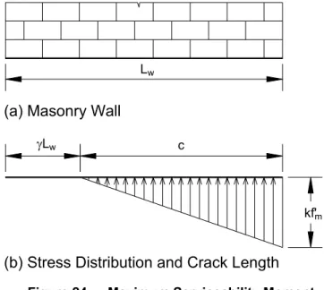
- Maximum Serviceability Moment
- Nominal Strength
- Yield strength
- Flexural Overstrength
- Ultimate Displacement Capacity
In this serviceability limit condition, the lateral force applied is generally greater than is necessary to cause cracks at the base of the wall. The moment of serviceability is limited by Me, which occurs when the stress in the extreme compression fiber at the base of the wall has reached kf'm, as shown in Figure 24. b) Stress distribution and crack length. At this bending condition, the relatively small deformations of the wall are believed not to result in a significant increase in tendon force or migration of tendon force eccentricity.
A better estimate of the nominal strength can be obtained from equation 31, if we take into account the increase in the tendon force ∆P and the related eccentricity of the tendon force et. It can be seen in Figure 26 that near the top of the wall there is a moment reversal due to et. The length of the compressive zone, c, is calculated at the nominal strength based on Eq.
46 predicts a linear variation of the increase in tendon force with respect to the lateral location of the tendons. In this equation etc. is the distance from the compressed end of the wall to the nearest tendon, and fps is the tendon tension in the same tendon at nominal strength. In general, the ultimate tendon tension is on the order of 5%, which would result in an unrealistically high displacement.
As the extreme concrete wall fibers fail, there is a tendency for the compression zone to migrate towards the center of the wall, reducing the wall strength gradually. Evaluation of the extreme masonry load at displacements beyond nominal bending strength necessitates the definition of a plastic hinge zone at the base of the wall.