Revision History
Air Handling Unit Safety Information
Introduction
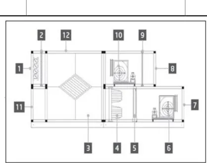
Each AHU unit can be equipped with various types of filters that are used to clean the air from small particles of dust, pollen, etc. Part of the exhaust air is mixed with fresh air so that the intake air temperature is closer to the desired one. These devices are used to regulate the air volume, and are often controlled via an inverter.
User interface
- Controller POL687/638 Interfaces
- External Human Machine Interfaces
- Push & Roll key HMI (POL895)
- WEB-Human Machine Interface
- Communication Modules
- Modbus module installation
- BACnet IP module installation
- Basic Control System Diagnostic
Both will replicate the exact same page as seen on the main controller and must be connected to the "T-HI" output on the controller. The Remote HMI can be extended up to 700 m using the Process Bus (PB) connection available on the main controller. The main controller can be connected to a PC using an Ethernet cable on the "Ethernet" output of the controller itself.
Any of the modules described in this section can be connected directly to the left side of the main controller to allow operation of a BAS or other remote interface. In case of Modbus connection to a BMS, the corresponding module must be installed in the unit (POL902). It must be connected to the unit controller as shown in the previous section.
In case of a BACnet connection to a BMS, the corresponding module must be installed on the unit (POL908). Unit controller, expansion modules and communication modules are equipped with two status LEDs, BSP and BUS, to indicate the operational status of the devices (see section 3.1 for their location).
Control Functions
Air Quality Control Function
The air quality control function provides the AHU with the ability to monitor and control the actual level of CO2 concentration in the environment by modulating the devices that control air flow (fans and dampers) to facilitate air exchange between indoors and outdoors. all the while ensuring that the selected temperature set point is respected. During this condition, the valves (both mixing and external) are modulated to increase fresh air flow. For additional information on air quality control logic and parameter configuration, see the Air Quality Control section (15.2).
The air quality control function is only available if the AHU has a CO2 sensor.
Humidity Control Function
For additional information on humidity control monitoring and parameter configuration, refer to the Humidity Control section (15.3). The humidity control function is available only if the AHU is equipped with all the necessary equipment.
Summer/Winter mode changeover functions
Main Menu screen
Status/Settings* Show actual status and manage settings for the devices installed in the AHU.
Control Source
Actual Mode
Unit State
See the Timer page (Section 14) for more details Ready: AHU in off state with timer.
Active Setpoint
Local Switch
Summer/Winter state
If the Su/Wi chg source = BMS, this value is the current state of the AHU. Time constant 0…36000 [h] Defines the frequency at which the check is performed for the Summer/Winter changeover in Auto mode. If this parameter is set equal to 6 hours, the controller maintains the same state (Summer or Winter) for six hours.
After six hours, the controller performs the check again to determine the next state that will be maintained for the next six hours. Su tmp -64..64 [°C] Switches to summer operation when the selected temperature is higher than this value. Wi tmp -64..64 [°C] Switches to winter operation when the selected temperature is lower than this value.
Setpoints
Refer to Summer/Winter Status (Chapter 11) for more details. Available from Airstream 0.10.B SW version and only if Return or Room temperature control is selected). Available from Airstream 0.10.B SW version and only if Return or Room temperature control is selected).
I/O Overview
Time Scheduler
Day Scheduler
Up to 6 time slots can be set by entering each daily page, normal or exception. If the time value is set incorrectly (i.e. less than the previous one), the AHU will not function properly and may always be ON or OFF.
Calendar exception and Calendar fix off
Status/Settings
- Temperature Control
- Air Quality Control
- Humidity Control
- Fans Control
- Fast Heating/Cooling
- Dampers Control
- Heat Recovery Control
- Cooling Coil Control
- Heating Coil Control
- ERQ Control
- ERQ Status
- ERQ Settings
- Post-Heating Control
- Pre-Heating Electrical Control
- Pre-Heating Water Control
Active setpoint - - Shows the actual supply fan setpoint used in the control logic (this value represents the sum of all functions that affect the supply fan setpoint). Active setpoint - - Displays the actual return fan setpoint used in the control logic (this value represents the sum of all functions that affect the return fan setpoint). Strt Tmp Err 5 °C 0 - 30 °C The fast heating/cooling function is only activated if the difference between the actual temperature setpoint and the controlled temperature is greater than this parameter at AHU start-up.
Start DT 2 °C 1 - 10 °C Set the temperature threshold between the set point and the actual controlled temperature for starting a new ERQ (this value represents the dead zone for activating ERQs). Shutdown DT 3.5 °C 1 - 10 °C Set the temperature threshold between the setpoint and the actual controlled temperature for closing an ERQ (this value represents the dead zone for disabling ERQs).
Alarm handling
Alarm restore
Alarm list
Disconnect the temperature sensor from the controller and measure the resistance value of the sensor. Heating coil pump alarm” (water coils separated or only one heating water coil present) of. Check the electrical power of the differential pressure switch Pressure is broken Replace the pressure switch.
Modify the unit's settings to reduce the percentage of CO2: - Increase the speed of the supply fan. The air quality sensor is not. This alarm occurs when the electric heater communicates an alarm condition to the controller via the "Electric Heaters Overload" digital input. This alarm occurs when the external device communicates to the controller (via the digital input "Frost Switch") that there may be ice on the external device's exchanger.
About Unit
Flashing - when the unit is in test mode or in off state through Panel Switch. This icon is On when the AHU is in Ventilation Mode This icon is On when the dehumidification control is active. Occupancy mode active. This icon is On when the AHU Summer/Winter changeover is set to Auto or Pursuit mode (if available) on the main controller (POL638/687).
The Occupancy is a function that allows the AHU to run for a fixed period of time (defined on the main controller under . "Status/Settings -> Occupancy Tm") when it is Off via time scheduler. This means that the Occupancy function can only work when the AHU is controlled via time scheduler HMI Path: Main Page → Ctrl Source = Local. The + or - buttons are used to define an offset from the Heat/Cool setpoint set on the main controller.
Pressing the + or - buttons on the main screen once will display the current set point. When the icon appears on the main screen of the room unit, the Su/Wi switching source on the main controller is set to Auto or Pursuit and the summer/winter mode cannot be changed via the room unit. The pipe must be sealed on the device side because air currents in the pipe can affect the sensor reading.
The D-AHU is fully compatible with Daikin's intelligent Touch Manager (iTM), which acts as a mini building management system and enables control of various AHU set points through its touch screen interface. If the AHU is equipped with a BACnet-IP communication module (POL908), it can be connected to the iTM via an Ethernet cable and controlled remotely. The following procedure allows the user to configure the iTM communication with the AHU controller and must be followed in order to properly configure both devices.
Press the "Network" button on the "System Settings" tab of the "Menu List" screen to display the network screen. In order to configure BACnet objects on the iTM, the user must log into Service Mode (SE) from the "Menu List" screen (see the iTM commissioning manual). Edit the "BACnet Server Device Instance" number to match the "Device ID" number configured on the BACnet communication module (POL908) on the controller.

