PARTS IDENTIFICATION
From the library of: Superior Sewing Machine & Supply LLC
7. PARTS IDENTIFICATION DRAWINGS 7.1. M700XL MACHINE LESS SEWING HEAD 7.1.1. FRAME ASSEMBLY
ASSEMBLY NAME: XL Frame Assembly ASSEMBLY FIG. NO.: 7.1 7. 2 REF. QTY. PART NO. DESCRIPTION
01 02 03 04 05 06 07 08 09 10 11 12 13 14 15 1 6 17 18 19 20 21 22 23 24 25 26 27 28 29 30 31 32 33
1 1 1 1 1 1 1 1 1 1 1 2 1 1 12 8 8 1 1 1 2 1 8 2 2 2 1 1 3 1 1 1 1
P6 20000 P530105 P530110 P530115 P530720 P530817 P530825 P530818 P520033 P6 2000 4 P620005 P620008 P6 20007 P620006 P520083 P840203 P6200ll P530823 P840188 P614000 P514003 P8 20044 P840148 P520024 P8 4 0 915 P620013 P6 20300 P220501 P840305 P840513 P840415 P520327 Bl6011
M700XL Table Assembly Control Logic Card CPU3 Card Assembly D-Ram Card Assembly CPU-CLC Cable
CPU Power Supply Fuse F4; lA, 250V Power Control Fuse F5; SA, 250V DC Drive Fuse F6; SA, 250V
Card Retainer
Left Front Panel - M700XL Right Front Panel - M700XL Side Panel - M700XL
Right Rear Panel - M700XL Left Rear Panel - M700XL
Screw #6xl/2" Lg., Type AB Phillips Decorative Head
Screw, #8-32 x 1/2" Lg. Type F Hex Head Tinnerman Clip for # 6 Type AB Screw Main Power Fuse F7; lOA, 250V
Screw #6-32xl/2" Lg. Slotted Pan Head M700XL Sewing Head Assembly
Head Hinge Pin V-Belt, 44"
Screw, #6-32x 3/8" Lg. Phillips Flt Head Head Hinge Plate
Rubber Hinge Insert (Grommet Z-399) Die Cut Corner Pad
Belt Guard/Bobbin Winder Assembly Template Holder Thumbscrew
Screw, Wood #7x3/4" Lg. Slotted Rnd Hd.
#6 Washer, Nylon
Screw, #6-32xl/4" Lg. Slotted Pan Head Guard Stop, Bobbin Winder
Anti-Static Mat
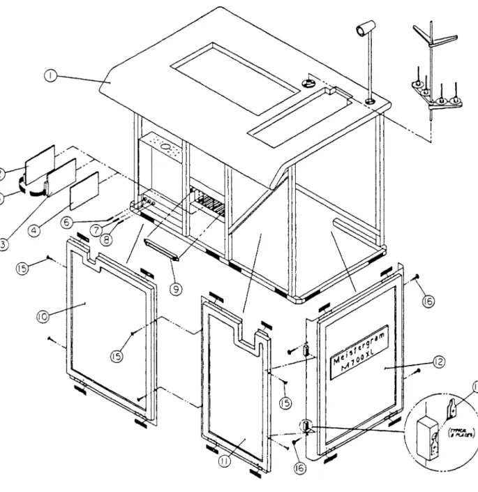
Fig. 7-1: Frame Assembly Drawing - Front
' "-.J
'
3
'--z_ __ _ /
M700XL MANUAL PARTS ID 7-2 1 OCTOBER 1984
From the library of: Superior Sewing Machine & Supply LLC
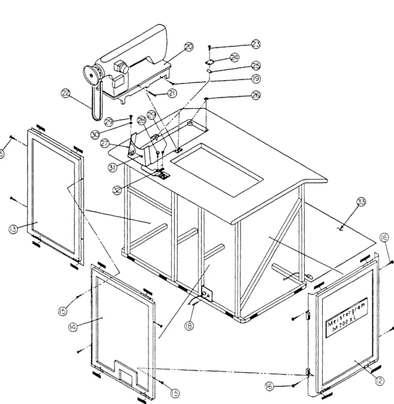
Fig. 7-2: Frame Assembly Drawing - Rear
/''•
'··
·---
7.1.2. Table Top Assembly
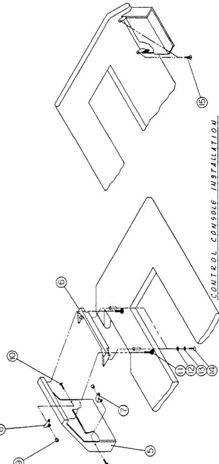
ASSEMBLY NAME: Table Top Assembly ASSEMBLY FIG. NO.: 7.3 7.4 7.5 REF. QTY. PART NO. DESCRIPTION
01 02 03 04 05 06 07 08 09 10 11 12 13 14 15 16 17 18 19 20
1 l 4 l 1 1 1 1 2 2 2 2 2 2 2 1 1 2 2 2
P6 20010 P840313 P520030 P530100 P630108 P620028 P6 200 2 7 P840795 P520081 P6 20103 P840530 P840572 P8 4044 0 P8 40304 P620500 P520501 P8 4 0 561 P840582 P840601
Table Top Assembly, M700XL
Pantograph Cover Assembly with Hinges
Screw, Wood #l0x3/4" Lg., Round Hd. Phillips Thread Stand, 4 Cone
Control Console Assembly Control Console Pedestal
Control Support Bracket, Right Control Support Bracket, Left Threaded Insert, #6-32
Screw , # 6- 3 2 x 5 I 8 11 Lg . , Decor at i ve Head
Thumb Screw, #10-32 x 111 Lg., 3/411 Dia. Head
#10 Flat Washer
#10 Lock Washer, Split
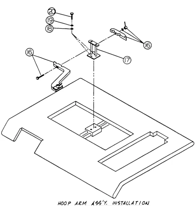
Screw , Mach i n e , # 1 0- 3 2 x 2 11 L g . , S lotted P a n H d Screw, Wood #6x3/411 Lg., Slotted Pan Head Hoop Arm Assembly, M700XL
Hoop Arm Base 5/16" Flat Washer
5/1611 Lock Washer, Split
Bolt, 5/1611-18x3/4" Lg., Hex Head
M700XL MANUAL PARTS ID 7-4 1 OCTOBER 1984
From the library of: Superior Sewing Machine & Supply LLC
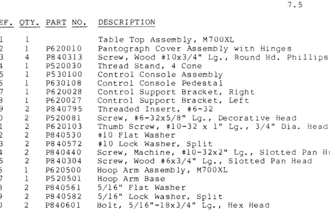
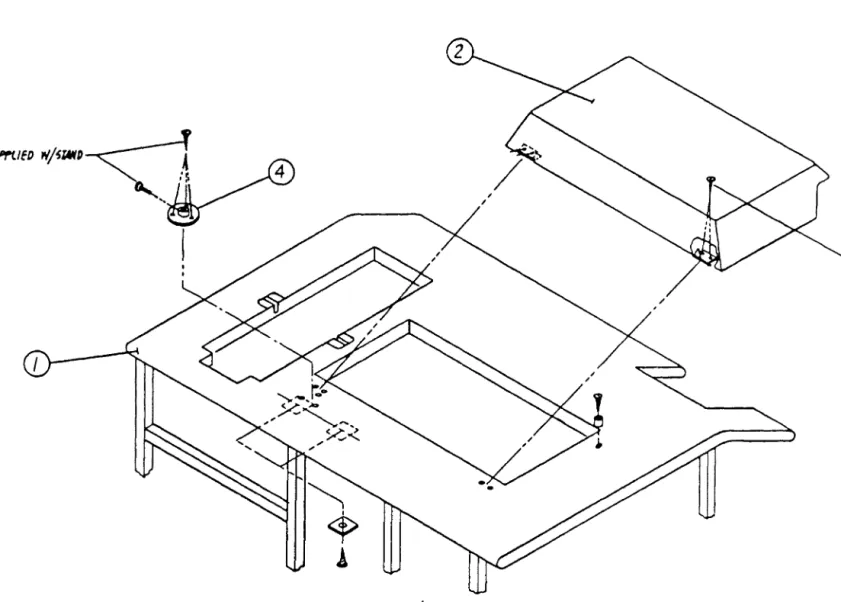
Fig. 7-3: Control Console Installation
I
I
\
\
Fig. 7-4: Pantograph Cover & Thread Stand Installation
SUffli€D
wj~r.D~~
~ /f\ 4
"
I
M700XL MANUAL
From the library of: Superior Sewing Machine & Supply LLC
PARTS ID 7-6 1 OCTOBER 1984Fig. 7-5: Hoop Arm Assembly Installation
JIOO P A£M A~ 'Y. IN~TALLA
r
I OAJ7.1.3. XL Sewing Head Assembly
ASSEMBLY NAME: Sewing Head Assy. ASSEMBLY FIG. NO.: 7.6 7.7 7. 8 7. 9 7.10
REF. QTY. PART NO.
01 02 03 04 05 06 07 08 09 10 11 12 13 1 4 15 16 17 18 19 20 21 22 23 24 25 26 27 28 29
1 1 1 1 2 2 2 2 2 l 1 l l l 2 1 l 1 l 2 2 l l l 1 1 l 1 1
P413001 P413022 P614038 P530408 P840916 P840410 P8405ll P61400 3 P413035 P413210 P413385 P614010 P312027 P840122 P8407 3 0 P8 40523 P614 0 4 0 P614030 P614050 P413004 P413003 P312013 P413017 P840725 P840189 P413018 P614052 P840401 P614025
DESCRIPTION
M700XL Sewing Head Assembly Cover, Stitch Width Motor Cover, Head Interface Card Head Interface Card
Rubber Grommet, 2-633
Screw, #6-32 x 3/8" Lg.Slotted Pan Head
#6 Lockwasher, Internal Tooth
Standoff, #6-32 x 3/4" Lg., Male-Female Hex Standoff, #6-32 x l/4" Lg., Male-Female Hex Thread Break Sensor Assembly
Screw, # 1 0 6 50
Tension Release Solenoid Assembly Ty-Rap
Screw, #8-32 x l/2" Lg. Slotted Flat Head
#8-32 Hex Nut
#8 Lockwasher, Split PT/NPS Pick-Up Assembly PT/NPS Sender Assembly
Stitch Width Motor Assembly Support Post, 2" Lg.
Support Post, 1 3/4" Lg.
Coupling, Stitch Width Motor Collar
#6-32 Hex Nut
Screw, Mach. #6-32 x 3/4" Lg. Slotted Pan Hd Magnet
Bracket, Stitch Width Limit Sensor Mounting Screw, #4-40 x 1/8" Lg. Slotted Pan Head Stitch Width Limit Sensor Assembly
M700XL MANUAL
From the library of: Superior Sewing Machine & Supply LLC
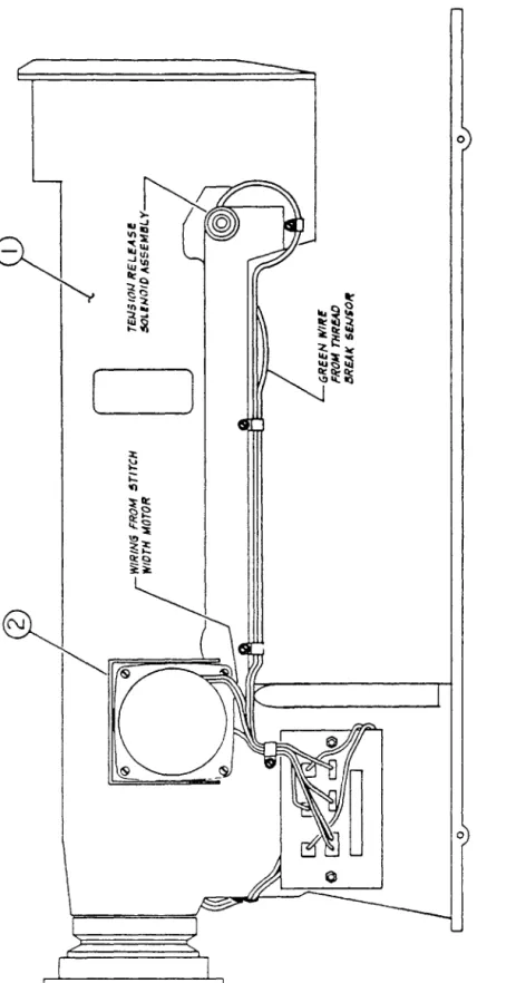
PARTS ID 7-8 1 OCTOBER 1984Fig. 7-6: Wire Routing and Head Interface Card Wiring
0
(________..]
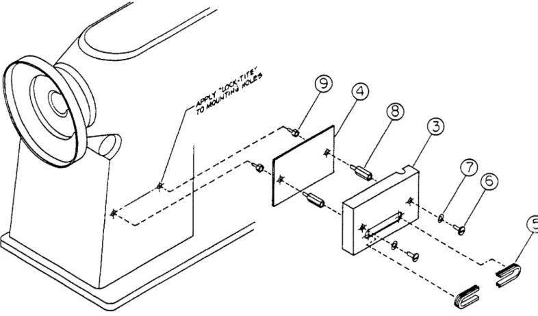
Fig. 7-7: Head Interface Card Assembly
HEAO INTERFACE CARD ASSEMBLY
M700XL MANUAL
From the library of: Superior Sewing Machine & Supply LLC
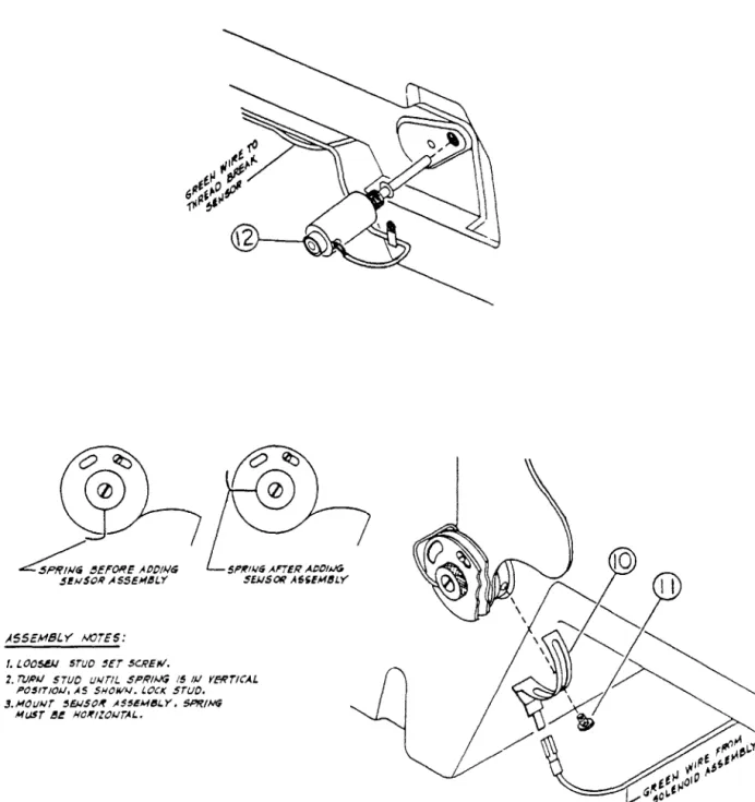
PARTS ID 7-10 1 OCTOBER 1984Fig. 7-8: Mounting - Thread Break Sensor Assembly
ASS EMS/. Y WrES:
f. £.00581 STUD 5ET SCREW.
5f'/rl!.l6 AnER ADOIWG 5EJJSOR A6SEM~LY
2. TUPJJ STUD U!.ITIL .Sf'RI~ 15 I)/ YEWrtCA.L f'0$1T!OIJ, AS SHOIIIAI. t.OCK STUD.
3.MOIIWT ~EJ.ISO~ .ASS~MI!JI.Y, SPRING MIJSr e~ HO~IlOI..ITAL.
MOUNTING- THREAD BREAK SENSOR ASSEMBLY
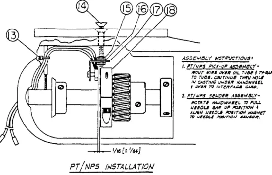
Fig. 7-9: PT/NPS Installation
_..,___ '116 (! 1164]
).SSEM~LY IJ5T!i'UCTIO/o./$:
/. f'T/Wf!!'~ PtCJ(·(JI' &S:;~f1~t.Y'·
MJIJr lf'l,qE OYIII OIL. TIJU f T'f41&41'
ro rue•. CtJIJTtJ.JIJ~ rwlfiJ J.tOI.I Ill ~rlll<i IJWDIIf N.ANDfiiHI!L , O(U T'O IJ.Jr~RA4.~ C41lD.
%. PT/J.JI"S $~1JO~R A"IM&Y-
~T'ATI H4J.JOWN6~1. 7t' l'lJU.
IJE~OU ~~~ Ill' 1'0$/TICII ~ A~IJ JJIIOLI I'CfiTJCw JM4N~
'!rJ J.J~EOI.I 1'01$1rJOI>I 61J.J~If.
PT /NPS /NSrALLAT!OfJ
Fig. 7-10: Stitch Width Control Drive Assembly
ASSEMBLY !W5rRUCi~~S:
f, ,(L COLLAR· SET STtrcN NIOTH JJJDIC).TO!f
to U:Ao i :luaJJ /ttiNlJJEr 11ml $T1rc11 111/Dnl $WSOR.
z.ALI.OW ~AS[! Vu] G.4l' UT'N~DI /14A<JWET I
5TifCJ( WIOT'H MJJ,SOR.
STITCH WfOTH COJ../TROL ORtVE ASSEMBLY
M7 OOXL
From the library of: Superior Sewing Machine & Supply LLC
MANUAL PARTS ID 7-12 1 OCTOBER 19847.1.4. XL Power Transformer Assembly ASSEMBLY NAME: XL Power
Transformer Assy
ASSEMBLY FIG NO.: 7.11
REF. QTY. PART NO. DESCRIPTION 01
02 03 04 05 06 07 08 09 10 11 12 13 14 15 16
1 1 1 2 1 1 2 2 4 2 2 2 1 4 1 1
P820033 P520105 P335167 P840740 P530500 P8 40 57 2 P530519 P520107 P8405ll P520103 P840720 P840201 ]840440 P840197 P840576 P840770
Strain Relief Connector Power Cord
Fuse Holder
#10-32 Hex Nut
Transformer Assembly
#10 Lockwasher, Split Marker, Terminal Strip
Self-Clinch Stud, #6-32 x 7/8"
#6 Lockwasher, Internal Tooth
Standoff, #6-32 x 3/8" Hex Internal Thread
#6-32 Hex Nut
Screw, #6-32 x 5/8" Lg. Type 11F11 Hex Head Screw, #10-32 x 211 Lg. Slotted Pan Head Screw, 1/4-20 x 1/2" Lg. Type 11F11 Hex Head
#10 Lockwasher, Internal Tooth 1/2" Lock Nut
Fig. 7-11: Frame - Lower Left Corner
\
s
M700XL MANUAL
From the library of: Superior Sewing Machine & Supply LLC
PARTS ID 7-14 l OCTOBER 19847.1.5. XL Frame Assembly -Front View ASSEMBLY NAME: XL Frame Assy.
REF. QTY. PART NO. DESCRIPTION 01 2 P520068 Leveling Foot
ASSEMBLY FIG. NO.: 7.12 7.13 7.14
02 1 P530412 Diagnostic Circuit Board 03 1 P530025 Card Cage Assembly
04 3 P8 4 018 9 Screw, Mach. , #6-32 X 3/4" Lg. Slotted Pan Hd 05 3 P840509 #6 Lockwasher, Split
06 3 P840720 #6-32 Hex Nut 07 3 P8 40510 #6 Flat Washer
08 4 P84041 7 Screw, Mach. , #8-32 X 3/16" Lg. Slotted Pan Head
Fig. 7-12: Power Installation
Control Cover, Diagnostic Board &
fOWEl COIIT~O~ CO'rf:£1 DIJ6#05TIC 80,/lO
I
~€Y€Uilq fffT IN5TAlLATION~
M700XL MANUAL PARTS ID 7-16 l OCTOBER 1984
Leveling
From the library of: Superior Sewing Machine & Supply LLC
Fig. 7-13: Card Cage & Decal Installation
CA2D CAG;
f
OfCJl !JIST.4lLIT/OIJFig. 7-14: Card Cage Shield/Enclosure Installation
.. .. ...
CA~O C.4GG Sii/ELD /E).ICL0'5UR€ !iJ~TAlL4T/0,4J
•
M700XL MANUAL PARTS I D 7-18 1 OCTOBER 1984
From the library of: Superior Sewing Machine & Supply LLC
7.1.6. XL Pantograph Assembly
ASSEMBLY NAME: XL Pantograph Assy ASSEMBLY FIG. NO.: 7.15 7.16 7.17 7.18 REF. QTY. PART NO. DESCRIPTION
01 02 03 04 OS 06 07 08 09 10 11 12 13 14 15 16 17 18 19 20 21 22 23 24 25 26 27 28 29
1 4 4 4 4 1 1 8 7 1 1 1 11'
6 9 1 1 1 1 1 1 2 4 8 4 4 2 2 4
P620400 P8 4 014 2 P520509 P520402 P520406 P520072 PS20074 P840540 P840915 P840710 P840785 P620003 9PS20001 P8 40059 P840203 P6 20055 P520053 P840730 P630300 P530414 P530400 P520062 P840603 P8 40 5 61 P840582 P8 40 7 0 7 P520066 P520064 P8 4 0 410
Pantograph Assembly, M700XL
Screw, Mach. 1/4-20 x 1 3/411 Lg. Slotted Flat Head
Neoprene Well Nut, 1/4-20 Thread Rubber Grommet, Z-148
T-Nut, 1/4-20 x 7/1611 Plain Slab Base Head Locking Screw
Head Locking Screw Spring 1/411 Flat Washer, Plated Rubber Grommet, Z-399 1/4-20 Hex Nut
4 Prong Black Fingernut Table Top, M700XL
111 Wide x 7/1611 Thick Adhesive Back Neoprene Strip
Screw, 1/4-20 x 2 1/211 Lg. Socket Head Screw, #8-3 2 x 1/211 Lg. Type F Hex Head Pantograph Pan
Drip Pan
#8-32 Hex Nut DC Motor Assembly
CPU Power Supply Cover CPU Power Supply Assembly
311 Dia. x 1 1/411 Wide Durafoam Wheel Bolt, 5/16-18 x 111 Lg. Hex Head
5/16" Flat Washer
5 I 1 6 11 Lo c k wash e r , S p 1 i t 5/16-18 Hex Nut
Axle, Whee 1 Locknut, Wheel
Screw, Mach. #6-32 x 3/811 Lg. Slotted Pan Head
Fig. 7-15: Pantograph & Head Locking Screw Installation
~
I!----@ I
M700XL MANUAL PARTS ID 7-20 l OCTOBER 1984
~
I IFrom the library of: Superior Sewing Machine & Supply LLC
Fig. 7-16: Table Top Installation
I I
~ I
Fig. 7-17: Drip Pan Installation
0£/P PAN !}JSTAlLATIQW
M 7 0 OXL MANUAL PARTS ID 7-22 1 OCTOBER 1984
From the library of: Superior Sewing Machine & Supply LLC
Fig. 7-18: CPU Power Supply, D.C. Motor & Wheel Installation
CPU !'OWER. t;IJPI'I.Y I DC M~roe
I
w!I;€L J»$TAUATIM7.1.7. XL Electrical Wiring
ASSEMBLY NAME: XL Electrical Wiring ASSEMBLY FIG. NO.: 7.19 7.20 7.21 7.22 REF. QTY. PART NO. DESCRIPTION
01 1 P530750 Main Frame Harness
02 1 P630755 Pantograph Limit Harness 03 1 P630710 Ribbon Cable, Head Interface 04 1 P630715 Display Power Harness
05 1 P530730 Ribbon Cable, PE to CLC
06 1 P530725 Ribbon Cable, Console To CLC 07 1 P530503 Diode Harness
M700XL MANUAL PARTS ID 7-24 1 OCTOBER 1984
From the library of: Superior Sewing Machine & Supply LLC
Fig. 7-19: Electrical Wiring - Front View
Fig. 7-20: ElectricaL Wiring - Side View
M700XL MANUAL PARTS ID
r - - - -
cl'tJ ff)IV{.e 9JPPr.Y
I ,.
I
I
~~~~~~~~~~TII I
I
.___
_____ _
7-26 l OCTOBER 1984
I
I
I I I
From the library of: Superior Sewing Machine & Supply LLC
Fig. 7-21: Electrical Wiring - Bottom View
Fig. 7-22: Electrical Wiring - Rear View
M700XL MANUAL PARTS ID 7-28 1 OCTOBER 1984
From the library of: Superior Sewing Machine & Supply LLC
7.1.8. XL Control Console Assembly ASSEMBLY NAME: XL Control Console
Assembly
ASSEMBLY FIG. NO.: 7.23 7.24 REF. QTY. PART NO. DESCRIPTION
01 02 03 04 OS 06 07 08 09 10 11 12 13 14 15 16 17 18 19 20 21 22 23 24 25
1 1 1 1 1 1 1 1 1 1 1 2 1 1 1 1 1 13 2 12 1 1 1611
1 1
P530100 P630102 P520012 P520016 P520018 P520020 P840562 P530129 P530716 P530125 P530108 P520029 P330440 P530103 P530735 P840505 P530785 P840511 P520081 P840150 P840410 P530795 9P891300 P6 3 013 9 9P530400
Control Console Assembly Control Housing Set
Switch, Illuminated Power Safety Switch DPST
Switch, Stop
Red Button, Stop Switch
7/1611 Flat Washer, 1/2" I.D. x l" O.D.
Console Switch Shield
Display Power Harness, Short Tape Drive
Keyboard
Mounting Bracket, Keyboard Display
Filter, Display
Ribbon Cable, Keyboard to Display
#4 Lockwasher, Internal Tooth Console Stop Switch Harness
#6 Lockwasher, Internal Tooth
Screw, #6-32 x 5/8" Lg. Decorative Head Screw, #6-32 x 1/4" Lg. Phillips Round Hd Screw, #6-32 x 3/8" Lg. Slotted Pan Head Console Power Harness
22 Ga. Wire, Green Bezel, Display Fish Paper
Fig. 7-23: Control Console Assembly
l
fM700XL MANUAL PARTS I 0 7-30 l OCTOBER 1984
From the library of: Superior Sewing Machine & Supply LLC
Fig. 7-24: Control Console Assembly
7.1.9. XL Power Control Assembly
ASSEMBLY NAME: XL Power Control Assy. ASSEMBLY FIG. NO.: 7.25 7.26 7.27 REF.
01 02 03 04 OS 06 07 08 09 10 11 12 13 14 15 16 17 18 19 20 21 22 23 24 25 26 27 28 29 30 31 32 33 34 35 36 37
QTY.
1 1 1 1 1 2 4 1 2 2 1 2 1 4 3 6 12"
4 8 1 30 10 10 6 7 7 15 17 17 8 10
9 6 6 l 1 1
PART NO.
P530200 P530201 P530203 P530117 P530ll9 P530221 P530217 P530220 P530120 P530205 P530765 P330448 PS 30340 P530227 P335167 P840520 9P530200 P840167 P8 4016 9 P840917 P8405ll P840410 P840725 P840404 P840631 P840523 P840732 P840420 P840576 P840450 P530213 P840508 P840505 P840715 P530775 P530780 P530790
DESCRIPTION
Power Control Assembly Power Control Enclosure D.C. Motor Drive Board P.E. Board
M.C. Board
1.5 Ohm 50 Watt Power Resistor 1.2 Ohm 100 Watt Power Resistor 10 Ohm 25 Watt Power Resistor 54,000 mfd at 20V D.C. Capacitor Mounting Bracket, Capacitor
Power Control Harness
Line Filter, 120/240V at 5 Amp Diode Heat Sink Assembly
Teflon Insulator Fuse Holder
#8 Flat Washer Grommet Strip
Sheet Metal Screw, #6 x 1/4" Lg. Slottea Pan Head
Sheet Metal Screw, #6 x 1/2" Lg. Slotted Pan Head
1/2" Plastic Bushing
#6 Lockwasher, Internal Tooth
Screw, #6-32 x 3/8" Lg. Slotted Pan Hd.
#6-32 Hex Nut, Small Pattern
Screw, #4-40 x 3/8" Lg. Slotted Pan Hd.
#8-32 x 5/8" Lg. Self-Clinch Stud
#8 Lockwasher, Split
#8-32 Hex Nut, Small Pattern
Screw, #10-32 x 3/8" Lg. Slotted Pan Hd.
#10 Lockwasher, Internal Tooth, Brass Screw, #8-32 x 3/8" Lg. Slotted Pan Hd.
Standoff, #6-32 x 1" Lg. Hex Male-Female
#8 Lockwasher, Internal Tooth
#4 Lockwasher, Internal Tooth
#4-40 Hex Nut KBIC Harness MC-PE Harness
Resistor Harness
M700XL MANUAL PARTS ID 7-32 l OCTOBER 1984
From the library of: Superior Sewing Machine & Supply LLC
Fig. 7-25: Power Control Assembly Front View
0 0
Fig. 7-26: Power Control Assembly Rear View
M700XL MANUAL PARTS I D 7-34 1 OCTOBER 19B4
From the library of: Superior Sewing Machine & Supply LLC
Fig. 7-27: Power Control Assembly Side View
7.1.10. XL Sewing Head Top Cover, Face Plate, Thread Guide & Thread Tension
ASSEMBLY NAME: XL SEWING HEAD ASSEMBLY FIG. NO.: 7.28
REF.
6031 8060 10551 10650 10675 10678 10679 10682 10685 10691 10692 10694 10695 10697 10789 10791 10792 10793 11006 11160 12048 13076 15004 15007 15025 15035 15036 15037 15038 15039 15055 15062
35504 35556 35557 35578 35582 35585 3 5 612C 90000
QTY.
2 1 1 2 1 2 2 1 3 2 1 1 1 3 1 1 1 1 1 1 1 1 1 7 1 1 1 1 2 8 1 1 1 1 1 1 1 1 1 1
M700XL MANUAL
TOP COVER, FACE PLATE,
THREAD GUIDE & THREAD TENSION PART NO.
P413225 P413240 P413298 P413385 P413405 P413408 P413409 P4134ll P413414 P413420 P413421 P413423 P413424 P413426 P413489 P413491 P413492 P413493 P413503 P413525 P413529 P413541 P413551 P413553 P413557 P413565 P413566 P413567 P413568 P413569 P413571 P413578 P413750 P413805 P413806 P413842 P413846 P413849 P614065 P614010
PARTS I D
DESCRIPTION
Throat Plate Screw Screw
Needle Bar Connecting Link Rear Guard Screw
Tension Bracket
Tension Release Lever
Tension Release Lever Screw Thread Guide Upper
Screw
Thread Disk
Tension Release Washer Thread Controller Disk Disk Screw
Tension Thumb Nut Tension Stud
Tension Bracket Pin Thread Controller Stud Tension Release Plunger Thread Guide, Top Cover Thread Guide, Middle Tension Release Spring Nut For Upper Thread Guide Top Cover Gasket
Screw
Take Up Lever Guard Face Plate
Face Plate Hinge Face Plate Spring Rubber Plug
Screw Screw
Thread Retainer Top Cover
Throat Plate
Throat Plate Locating Pin Spring
Tension Release Lever Rod Thread Guide, Lower
Thread Break Sensor Assembly
Tension Release Solenoid Assembly
7-36 1 OCTOBER 1984
From the library of: Superior Sewing Machine & Supply LLC
:s:
---.)
0 0
><
L' 3:
:P z c :P L'
t-o :P
~
~ U)
H
0
---.)
w I
---.)
f---J
0 n
~ c
OJ [TJ
~ f---J
\..D co
~
J.SC36
!.)OJ'?
60.31 ((D~SOJq
~~
IS037
T1
.35556
"oos!j e-
150-'613076 ~
_., /v
®
1$()()1i--:- --
ISOo4
116~1
I
/j(){K.106Tq 1#678 0 '
1'-~ '
~
0 10109 •~
150jjJS~B~
~
10'!'1:07 ..
l'tj 1-'·
\0
.
....,J I
"'
co
~
ro 0
n
0
<
({)
~
'TJ OJ 0 ({)
... t-o OJ rt ({)
~ ::r
~
J)
I06Be ({)10~ ~~
11160 1055/
r;;;JJ
~ ~
106'11 Cl'~
1019l c<!i? I
<0' , ..---
1r0411 "'·8060 ID19i!
~
0{§)
(C~ /~ ~
.J557B II[}
~ ~
,.,I ~ v ~
v.
I~\
IO(iqT ::rOJ 0..
35551 B
I068S
106.50
n6H ~
1161.5 10691 ({)
--- J~
-'.5585 35612C~ g;
~ ({)::J
7.1.11. XL Sewing Head Arm Shaft & Thread Take Up
ASSEMBLY NAME: XL SEWING HEAD ASSEMBLY FIG. NO.: 7.29
REF.
10504 10506 10520 10521 10522 10523 10524 10528 10562 10563 10566 10571 10576 10577 10579 10725 10726 10728 10729 10764 10766 10771 11012 11042 13081 13423PB 15013 15026 15033 15034 15038 17011 17012 17013 17014 17017 17018 17019 18003 35505 90001 90002
QTY.
1 1 1 1 1 1 4 1 1 1 3 3 1 1 1 4 1 1 1 1 2 1 1 1 1 1 1 1 1 1 1 1 1 1 1 1 1 1 1 1 1 1
M700XL MANUAL
ARM SHAFT & THREAD TAKE UP PART NO.
P413250 P413252 P413266 P413267 P413268 P413269 P413270 P413274 P413310 P413311 P413314 P413319 P413324 P413325 P413327 P413437 P413438 P413439 P413440 P413464 P413466 P413471 P413509 P413515 P413543 P413549 P413555 P413559 P413563 P413564 P413568 P413601 P413602 P413603 P413604 P413607 P413608 P413609 P413650 P413751 P614030 P614040
PARTS I D
DESCRIPTION Balance Wheel
Arm Shaft Oil Packing Stop Screw Needle Bar Crank
Screw Set Screw
Needle Bar Connecting Link Stud Set Screw
Needle Bar Connecting Link Arm Shaft Bushing, Front
Arm Shaft Bushing, Front Washer Set Screw
Set Screw Screw
Balance Wheel Adjusting Screw Set Screw
Oi 1 Fe 1 t Oi 1 Wick Oil Wick Oi 1 Wick Set Screw Set Screw
Lifting Eccentric Oi 1 Wick
Oil Wick Oil Felt
Stitch Length Indicator Take Up Lever Hinge Stud Take Up Lever Drive Stud Oil Wick for Arm Shaft Oil Wick Holder
Rubber Plug Arm Shaft
Arm Shaft Bushing, Middle Arm Shaft Bushing, Rear Arm Shaft Bushing Collar Arm Shaft Gear, Spiral Set Screw
Set Screw
Thread Take UP Lever Feed Fork Collar
PT/NPS Sender Assembly PT/NPS Pick Up Assembly
7-38 1 OCTOBER 1984
From the library of: Superior Sewing Machine & Supply LLC
3:
--...)
0 0 ><
r
3:
~ z
c ::t:>'
r
t-el ::t:>'
~
t-3
(/)
H
0
--...)
w I 1.0
f---'
0
~
c t-3 OJ tTJ
~ f---' 1.0 co J:o.
105~4 110~
I07l6
IOU.S
~ ~
IS034:__r g
tiOIZ.-
10711
~
JOS66
~
/0571
~
J()125
~ ~
JOJi!l
IOSZ<l
"
/017:.5
/DJTI
@
' 1 7 0 / l !
1057q
IJ4Z3P-8 Jo.5'TI lOS"
170/9-ia'
~,
..3~~ /~~
li7ii>
~-~
900021=4
~
~" ,,'e
10577
IOS76
P'%j
...
~
~ I
tv
~
::t:>' 1-'i
~ (/)
::r
OJ t-t, rt OJ ::J Q.
::r t-3 1-'i
([) OJ Q.
t-3
OJ
;A ([)
c
I'CJ
7.1.12. XL Sewing Bead Needle Bar (Swing Mechanism)
ASSEMBLY NAME: XL SEWING HEAD ASSEMBLY FIG NO.: 7.30
REF.
4134 4221 8105 10519 10524 10525 10531 10532 10537 10560 10561 10580 10581 10582 10724 10726 11042 11176 12421 12626 13084 15031 15069 15076 17048 17063 18018 18065 35506 35507 35508 35509 35512 35513 35514 35515 35536 35537 35538 3 5539 35540 35552 35553 35554 35555
QTY.
1 1 3 1 2 2 1 1 1 1 1 1 l 1 1 1 1 4 1 1 1 l 1 1 l 1 3 2 1 1 1 2 1 1 1 1 1 1 1 1 1 1 1 1 1
M700XL MANUAL
~EEDLE BA~WING MECHANISM) PART NO.
P413205 P413213 P413247 P413265 P413270 P413271 P413278 P413279 P413283 P413308 P413309 P413328 P413329 P413330 P413436 P413438 P413515 P413527 P413533 P413535 P413545 P413561 P413581 P413585 P413638 P413641 P413660 P413699 P413752 P413753 P413754 P413755 P413758 P413759 P413760 P413761 P413782 P413783 P413784 P413785 P413786 P413799 P413802 P413803 P413860
PARTS I 0
DESCRIPTION Screw
Oil Wick Clamp Nut
Screw Set Screw Set Screw
Needle Bar Connecting Stud Screw
Needle Bar Rock Frame Hinge Stud
Needle Bar Rock Frame Position Bracket Screw
Needle Bar Rock Frame Slide Block Stud Set Screw
Needle Bar Rock Frame Slide Block Oi 1 Wick
Oil Wick Oi 1 Wick Set Screw Set Screw Needle Screw Nut
Oil Wick Oil Wick Cotter Pin
Needle Bar Rock Frame Shaft Collar
Hinge Screw Screw
Stitch Width Drive Gear Stitch Width Cam
Stitch Width Cam Shaft Shaft Collar
Stitch Width Cam Follower Pivot Link
Shaft for Pivot Link
Shoulder Screw For Pivot Link Pivot Connecting Bracket
Pivot Shaft
Needle Bar Rock Frame Shaft Crank Conn.
Needle Bar Rock Frame Shaft Crank Oil Wick
Needle
Needle Bar Frame Needle Bar
Needle Bar Thread Guide
7-40 1 OCTOBER 1984
From the library of: Superior Sewing Machine & Supply LLC
3:: 10Sl5 .35553
3Sf8 ~
180/lj---.1
.35539
0
~
\
0
()
><
8105
["4
~ ~D
11116
1-Zj
3:
.3-ll"Oq
...
:P
35so1 \
B
1.0
z
.
c
M506
:P
I .
...,
["4 IOSJ7
IOS/9
I
w I
~
0
..
l"lj
107e$
~
:P
I
z
:::c
1058/ 8105
I
(1)
t-3
11176
(1)
(f)
<9/
Ia,
lil
f-'
H
(1)
0 IOSJ-e
®
3.55/l. II04C
D:J
~
OJ
1()560 /""...II U'-'./1
::n
t"1---.1
ro
I~ ~'
Ul
I
~1
IOJBC~
~
16018
/1116
...
f-'
I01e.4 ,J~4 355/j
::J
(§('13084 tO
3550~
(1) 3:: 0~4134- ::r
OJ ::J ...
di> tc6c6
f-'
IS06~
35555_/ In I
0
35554
3.5536 ~r- -
.3SS40
I }}
---~- Ul 3n t-3 0 D:J tiJ
~
f-'
"
~
I
~J 3555c / / ..J,J,J..JI\ / _/ ..._,. B\. - ~ - Jc4C/
co
~
7.1.13. XL Sewing Head Presser Bar & Components
ASSEMBLY NAME: XL SEWING HEAD ASSEMBLY FIG. NO.: 7.31
REF.
2031 8146 10514 10532 10538 10541 10543 10545 10549 10628 10660 10662 10703 10705 10706 10754 10761 10772 10773 10774 10775 10776 11156 12909 13065 15007 30078 35541 35542 35543 35544 35548 35549 35550 35551 35569 35583 35591
QTY.
1 2 2 1 2 1 1 1 1 1 1 1 1 1 1 2 3 1 1 1 1 1 1 1 2 2 1 1 1 1 1 1 1 1 1 1 1 1
M700XL MANUAL
PRESSER BAR & COMPONENTS PART NO.
P413203 P413249 P413260 P413279 P413284 P413287 P413289 P413291 P413295 P413365 P413390 P413392 P413432 P413434 P413435 P413454 P413461 P413472 P413473 P413474 P413475 P413476 P413523 P413537 P413539 P413553 P413725 P413788 P413787 P413789 P413790 P413795 P413012 P413797 P413798 P413815 P413847 P413855
PARTS ID
DESCRIPTION Screw
Nut
Sleeve Bearing Screw
Presser Bar Bushing
Presser Bar Position Guide Bracket Presser Bar Position Guide
Screw
Presser Bar Spring Bracket Set Screw
Screw Screw Washer
Presser Bar Spring, Flat
Support Screw for Presser Bar ~pring
Screw Set Screw Eccentric/Cam Needle Bearing Sleeve
Shoulder Stud Wing Nut
Presser Bar Spring Regulating Screw Presser Bar Eccentric Cam Link, Left Connecting Link Shoulder Screw
Screw Nut
Eccentric Cam Link Shaft
Presser Bar Eccentric Cam Link, Right Presser Bar Lift Brkt Conn. Link, Upper
Presser Bar Lift Brkt Conn. Link, Lower
Presser Bar Presser Foot
Presser Bar Lifter Stud Presser Bar Lifter Lever Presser Bar Lifter Bracket Pinch Screw
Lifter
7-42 1 OCTOBER 1984
From the library of: Superior Sewing Machine & Supply LLC
3:
-._]
c
0 ><
r
3 >-
c z
>-
r
'0 >-
~ t--3 en
H
0
-._]
I .f::-
w
1----'
n 0 t--3 0 OJ trJ
~ 1----'
\.D (X)
~
10154-
355CR
~
.355ql 30078\ \0
~\'
15001
355ll3
®
130t:~ m ®>6146
~~ ~~-35544
2031
10754
10176
6;J
li?.909 '0r~ ~I 10114~
10703 107'T5
1054-3 10761
~ f1
3555/
/06~ .cJ ~~
l
C)~ ''~"
10761
~ ~-10536
1056C.
~~-JDS41
~-35550
~ ,_1054-5
JD6C6
~
I 3S56<i
la5~ ~-1054q
1016/
~ ~-10536
. _ .
/0773
"Zj
...
1.0
.
~
-...J
\~1/ I
w
I-'
..
'0 t"i
11156 (1)
Ul Ul (1) t"i OJ OJ t"i
3554-8-
Q'1
n
0 3
'"0 0 :J
(1)
:J 10705 rt
Ul
3SS4q
35583
~
7.1.14. XL Sewing Head Connecting Rod, Lower Shaft & Hook
ASSEMBLY NAME: XL SEWING HEAD ASSEMBLY FIG. NO.: 7.32
REF.
6025 8009 10522 10571 17020 17021 17022 17023 17024 17025 17026 17028 18034 18037 18057 18058 18059 18060 35572 35573 35574 35574-1 35574-2 35574-3 35574-4 35574-5 35574-6 35574-7 35574-8 35575 35575-1 35575-2 35575-3 35575-4 35575-5 35575-6 35575-7 35575-8 35575-9 35576 50200
QTY.
1 3 1 1 1 1 6 1 1 1 2 1 1 1 1 1 1 1 1 1 1 1 1 4 1 l 3 1 1 1 1 1 1 1 1 1 1 1 1 1 2
M 7 0 UXL MANUAL
CONNECTING ROD, LOWER SHAFT AND HOOK
PART NO.
P413220 P413230 P413268 P413319 P413610 P4136ll P413612 P413613 P413614 P413615 P413616 P413618 P413670 P413674 P413695 P413696 P413697 P41369B P413818 P413819 P413820 P413821 P413822 P413823 P413824 P413825 P413826 P413827 P413828 P413830 P41383l P413832 P413833 P413834 P413835 P413836 P413837 P413838 P413839 P413840 P41386l
PARTS I D
DESCRIPTION
Bobbin Case Pos. Finger Screw Set Screw
Set Screw Set Screw
Arm Shaft Upright
Arm Shaft Upright Spiral Gear Set Screw
Arm Shaft Upright Gear, Lower Arm Shaft Upright Bushing, Upper Arm Shaft Upright Bushing, Lower Oil Felt
Lower Shaft Gear Spiral Bobbin
Hook Shaft Bushing, Rear Lower Shaft Bushing
Lower Gear Cover Complete Pinch Screw
Lower Gear Cover Sealing Screw Hook Drive Shaft
Hook Drive Shaft Thrust Collar Rotating Hook Assembly Complete
Hook Screw
Bobbin Case Assembly Complete
Hook Supporting Plate Set Screw
7-44 l OCTOBER 1984
From the library of: Superior Sewing Machine & Supply LLC
3:
--.]
0 0
><
L' 3: > z c >
L'
t-0 >
~
f---3
{F.
H
0
--.]
I
~ Ul
...
0 0 1-3 0 tJJ tiJ
~ ...
\.0
().) .l=:-
35574-1
3S.514-S ~
35575-i! 3SS7S-I
JS~( 3~14-~ ~ ._,
35.574-7/;5574-e• ~ 3!,4-8 J_l35574-3
~S1S~~
35575-SI ~
35575-7 6I
35575-4
JJ575
~
• J557S-'I575-6
1-
0.3557.5-8
.3.5574
~ ~~lV ~
~ 3.5514-1®~
35574-8M ~
&
6'0~.5
soeoo
~- It/
soc:.oo
17Dll
nor.r:. ~ ~ 110l'e
~tasu.
m /10~6
1701!5-
~ 1051/
m
l'fOl.6/10C:.C!
"""~
l:::::::J
~ITOC:5~e
\CJ 170U.
) 01 --- 18056
18060
800'1
'"r:l 1-'·
\0
...J
w I N
0 0 :J :J
(!)
0
(T 1-'·
:J lQ
,;
0
().,
0 L'
~ (!)
~
(f)
;:J
!.lJ Hl (T
~
:::c
0 0 7"
7.1.15. XL Sewing Head Stitch Width Regulation & Components
ASSEMBLY NAME: XL SEWING HEAD ASSEBMLY FIG. NO.: 7.33
REF.
4135 8042 8103 10566 10571 10766 12418 12421 15055 17063 18065 31118 35516 35517 35518 35521 35525 35528 35529 35530 35531 35532 35533 90003 90004 90005 90006 90007 90008 90009
QTY.
2 l l 2 l l 4 2 l l l l l l l l l 1 2 l 1 l 1 l l l l l l l
M 7 OOXL MANUAL
STITCH WIDTH REGULATION AND COMPONENTS
PART NO.
P413206 P413237 P413245 P413314 P413319 P413466 P41353l P413533 P41357l P41364l P413699 P413735 P413762 P413763 P413764 P413767 P41377l P413774 P413775 P413776 P413777 P413778 P413779 P413017 P840405 P413018 P614025 P84040l P8 4 0 715 P312013
PARTS ID
DESCRIPTION Lock Nut Set Screw Screw Set Screw Set Screw Set Screw Cover Screw Set Screw Screw Collar Screw
Coupling Drive Shaft Bushing Stitch Width Regulator Arm Support Shaft
Support Shaft Bushing Stitch Width Indicator
Stitch Width Assembly Cover Plate L i f t i n g C r a nk
Bearing Pin Connecting Bracket Bearing Pin, Long
Bearing Pin, Short
Stitch Width Regulator Connecting Arm Coupling Drive Shaft
Collar Screw Magnet
Stitch Width Limit Sensor Assembly Screw
Nut
Coupling
7-46 1 OCTOBER 1984
From the library of: Superior Sewing Machine & Supply LLC
Fig. 7-33: Stitch Width Regulation & Components
,.,.,,,.,.,.,
c.. . . ~-:.~
co ~
1\J ...