The preliminary structural size of a launcher is one of the fundamental steps in the design of that vehicle. Finally, after the fineness ratio of the vehicle is established, it is possible to determine the dimensional parameters of each structural element, using the Membrane Theory for shells of revolution.
Nomenclature
Acronyms
Introduction
Motivation
Increasingly, they can compete with government-backed agencies like NASA or ESA. There are various space companies that are now focused on producing heavier launch vehicles that can carry heavier payloads, aiming to reach new planets like Mars.
Topic Overview and Requirements
One way to send these satellites into orbit is to put them as secondary payloads – in other words, these satellites are not the main concern of the mission, as that role is taken by the larger payloads. The feasibility of this project needs to be decided, and therefore a feasibility study of the various systems in a launch vehicle is underway.
Thesis Outline
In this case, an aerodynamic analysis is chosen to determine the best ratio of fineness, that is, the best ratio between the length of the vehicle and its diameter. The results are then compared to the initial dry weight estimate to assess whether a new iteration is needed so that the requirements are met.
Bibliographic Revision
Structural Components
- Tanks
- Adapters
- Payload Fairing and Nose Cones
- Thrust Frame
- Secondary Structures
All the non-pressure structures used to connect the functional parts of the vehicle are considered adapters. An example of smaller lines are the pipes connecting the pumps to the engine, which are considered part of the propulsion subsystem [3].
![Figure 2.2: Example of spherical tanks: N1 Rocket. Reproduced from [8].](https://thumb-eu.123doks.com/thumbv2/123dok_br/19768583.0/29.892.338.547.102.422/figure-2-example-spherical-tanks-n1-rocket-reproduced.webp)
Propulsion
- Type of Propulsion
- Feeding System
The supply lines used to supply the propellant gases to the engine are the longest and largest lines and have the highest flow rates. Efficiency varies greatly not only depending on the type of propellant used, but also depending on the combination chosen.
![Figure 2.8: Schematics of a liquid rocket engine. Reproduced [16].](https://thumb-eu.123doks.com/thumbv2/123dok_br/19768583.0/33.892.275.575.607.870/figure-2-schematics-liquid-rocket-engine-reproduced-16.webp)
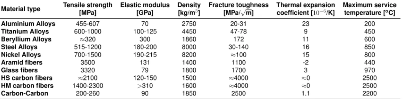
Materials in Launch Vehicles
To minimize it, propellants must be kept at a low temperature, in a compressed liquid state, to prevent immediate vaporization, because the lower the temperature, the easier it is for the liquid to maintain its liquid state when exposed to low pressures. It is then possible to use this type of delivery system while the tanks are under pressure, taking advantage of the structural stabilization provided by the internal pressure and the ability to deliver propellant gases to the pump without vapor entrapment.
Aluminium alloys
Currently, the lighter aluminum-lithium (Al-Li) alloys are used because of the weight saving advantage. For example, compared to 2219, the Al-Li alloy 2195 has a higher yield strength (about 20%) and is 8% stiffer, despite a lower density, resulting in a lighter structure [3].
Titanium
However, these alloys have some disadvantages such as reduced ductility, anisotropy of in-plane properties [24] and difficulty of acquisition. In general, aluminum alloys have good machinability, they can be chemically ground (as this is a common process, as it is an economical operation), and their properties are especially good in printing designs [24].
Beryllium
Nickel alloys
Steel alloys
Composites
To take full advantage of fiber-reinforced composites, multiple layers are usually combined, in which each layer is oriented in the direction that best suits the structural requirements. However, the matrix will reduce the tensile strength of the composite, thus adding weight while reducing the advantages of the fibers present. A complication arising from these materials is that the directional properties of the material are not readily available for use, making their selection more difficult.
One of the main characteristics of aramid fibers is that they fail in a ductile, more benign way, unlike the glass or carbon fibers [32].
Trade-off Studies
Comparison of Propellants
- Propellants Selection Criteria
- Propellant Selection
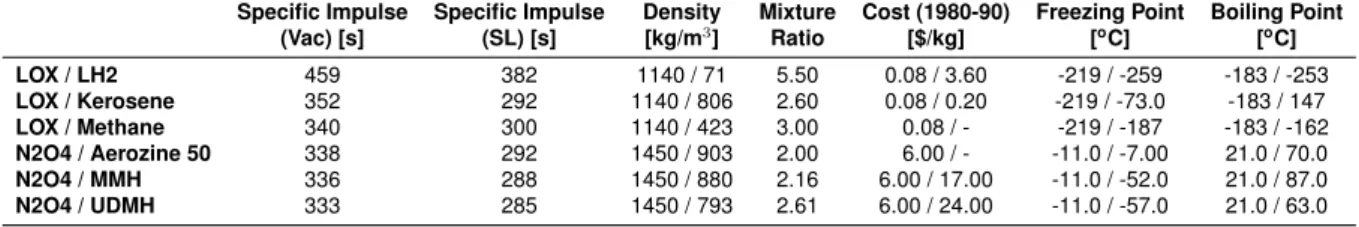
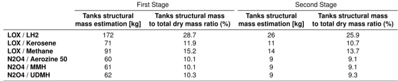
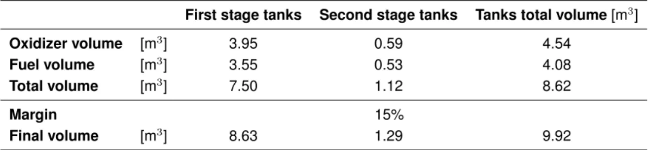
Knowing the operational requirements, presented in Table 1.1, the densities of the various fuels and oxidizers and their mixture ratios, i.e. the oxidizer to fuel ratios, the volume of the tanks can be calculated using Equations (3.1) to (3.5). This parameter is related to the ease of obtaining the propellants, that is, whether they can be obtained easily or not. In the case of the other propellants, they are chemical compounds that must be manufactured and may require safety procedures due to their toxic nature.
The boiling point was included in this analysis because it represents the ease of vaporization of the propellants.
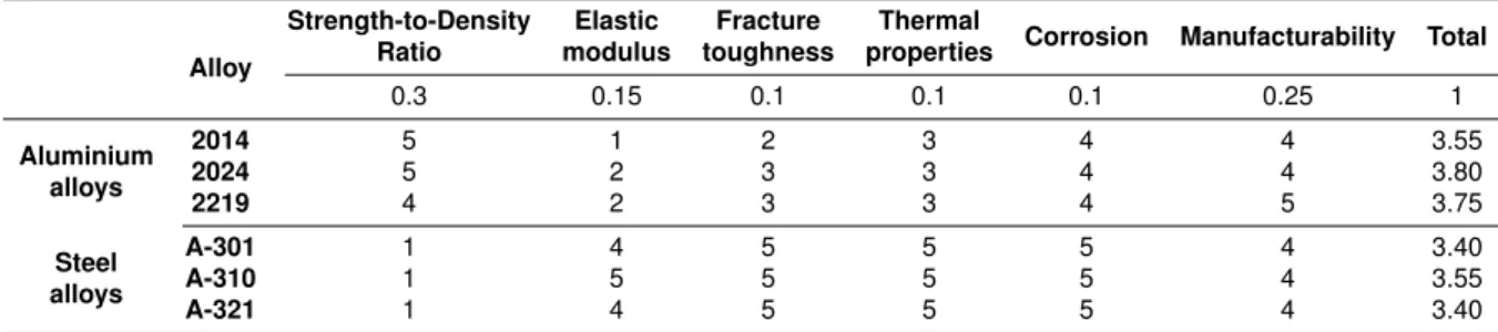
Comparison of Materials
- Materials Selection Criteria
- Material Selection
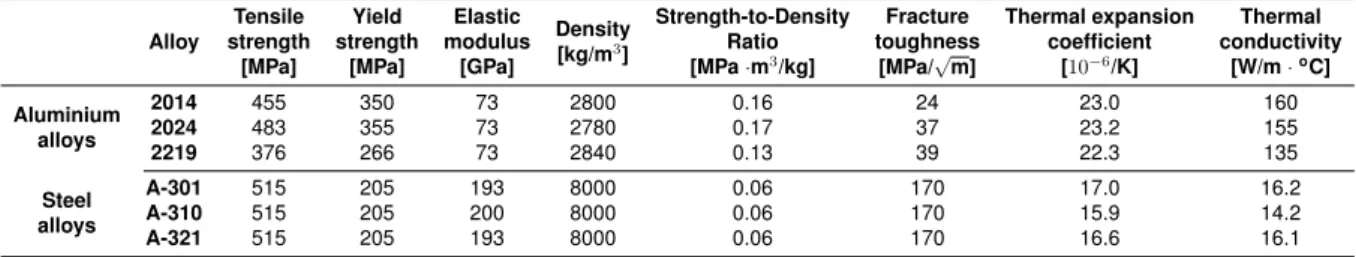
At cryogenic temperatures, the properties will be strongly influenced by the crystal structure of the material. Each structural component will have different material requirements, so they will be assessed individually in the following sections. As expected, when compatibility issues are not present, high strength carbon composite is the most suitable.
3 An average fracture toughness for the 7000 series aluminum alloys was determined according to the results presented in [47].
External Preliminary Sizing
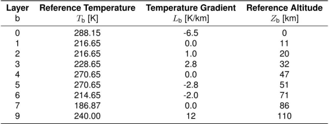
Atmospheric Model
- Temperature
- Pressure
- Density
- Mach number
T =Tb+Lb(Z−Zb), (4.1) where Lb is the temperature gradient, Tb is the reference temperature relative to Zb, the reference altitude, and Z is the considered altitude. The first, equation (4.4), is used when Lbi is different from zero, and the second, equation (4.5), when Lbi is zero. 4.5) The variables TbandLbare are defined in table 4.1, and Pb, which is the reference pressure, is defined in table 4.2. There are also two expressions that describe the density variation up to 86 km, presented in Equation (4.6) and Equation (4.7), with respect to the reference values (ρb) given in Table 4.4.
Again, the variation for altitudes above 86 km can be approximated using polynomial expressions, which are shown in Table 4.5.
Rigid Body Forces
- Thrust
- Drag Force
- Gravity Force
Looking at Figure 4.4, it is possible to define the reference area, as well as the nose and body wetted areas of the vehicle, as [55]. In the case of the supersonic regime, Barrowman's expressions, the results of which are presented in. The roundness of the nose cone is quantified by a bluffness ratio, the ratio between the tip and base diameters [60].
Finally, the force of gravity, or the weight of the vehicle, at each point of the trajectory, is given by.
![Figure 4.4: Launch vehicle scheme. Adapted from [55].](https://thumb-eu.123doks.com/thumbv2/123dok_br/19768583.0/59.892.309.555.651.887/figure-4-launch-vehicle-scheme-adapted-from-55.webp)
Launcher Preliminary Sizing
It is considered that the payload is a prism, but inscribed in a cylinder, for packaging purposes, as shown in Figure 4.13. From these values it is possible to determine the diameter of the cylinder, which will be given by Comparing the volumes of the cone and the cylinder, it is noted that the nose cone volume must be at least 2.25 times greater than the cylinder's.
Considering the length of the engines, which is 1 m for the second stage engine and 0.6 m for the first stage engines, it is finally possible to tailor the vehicle.
Ideal Fineness Ratio
Based on the analysis of the second stage, using equation (4.48), it is concluded that the gravity losses are approximately 2511.6 m/s. Moreover, the surface area of the spherical hemispheres increases with R2, so that as the radius increases, i.e. the fineness ratio decreases, the total dry mass of the stage also increases. Similarly, due to the increase in the total mass of the second stage, the mass of the first stage propellants will also increase since the total supported mass will be higher.
As a result, the required volume for first-stage tanks will increase, resulting in a decrease in the fineness ratio: for a constant maximum length, an increase in volume means an increase in radius.
![Table 4.10: Propellant and structural mass of the second stage for each fineness ratio Fineness ratio Thickness [mm] Dry mass [kg] Propellant mass required [kg]](https://thumb-eu.123doks.com/thumbv2/123dok_br/19768583.0/72.892.145.744.605.791/table-propellant-structural-fineness-fineness-thickness-propellant-required.webp)
Structural sizing
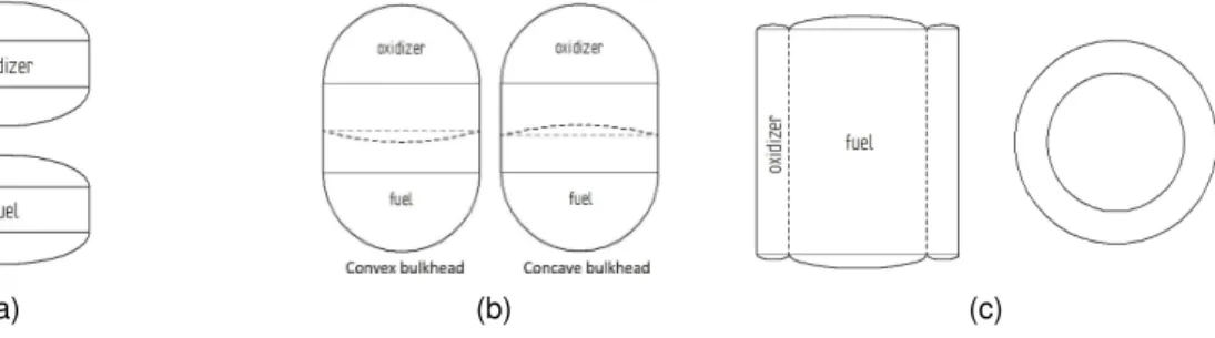
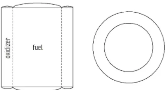
- Tanks’ Architecture
- Structural Loading
- Lift-off
- Maximum Drag
- Analytical Method
- Shells of Revolution
- Cylindrical Shells
- Materials’ Properties
- Analytical Results
- Numerical Results
In terms of tank production, it is expected that the more parts in the tank, the more complex its fabrication and assembly will be. With the critical load determined, it is possible to begin sizing the various components of the vehicle. The properties of the materials to be used are summarized in the next section, as their characteristics are needed for the calculations.
A more detailed description of the calculations can be found in Appendix C and the results are summarized in Table 5.6.
Conclusion
Achievements
Finally, the dimensioning of the vehicle's structural components was completed using the Membrane Theory for shells. During these calculations, it was verified that a spherical dish for the second phase is more advantageous than an ellipsoidal one, even if it means an increase in the total length, because it results in a lower structural mass. The first is to reduce the amount of propellant, which will result in smaller tanks and potentially increase the fineness ratio.
The second option would be to keep the same configuration, increasing the payload the vehicle can carry to the intended orbit.
Future Work
This will also lead to lower drag losses, potentially further reducing the required propellant mass. It is concluded that the launcher design obtained in this work can be used to meet the functional requirements set by Omnidea.
Bibliography
Retrieved May 8, 2017 from http://www.ilslaunch.com/newsroom/news-releases/failure-review-oversight-board-frob-concludes-investigation. Retrieved 2017, May 8, from http://www.ilslaunch.com/newsroom/news-releases/ils-frob-concludes-yamal-402-proton-launch-anomaly-investigation. Retrieved May 8, 2017 from http://www.ilslaunch.com/newsroom/news-releases/failure-review-oversight-board-frob-concludes-express-am4r-investigation-retu.
Onttrek 2017, 8 Mei van http://www.ilslaunch.com/newsroom/news-releases/ils- concludes-review-centenario-proton-launch-failure-investigation.
Appendix A
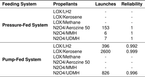
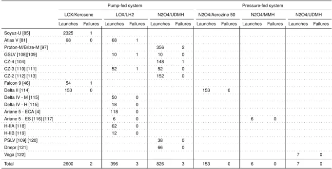
Propellants Reliability
Launch Vehicles Failures
The liquid oxygen pump caught fire possibly due to foreign particles present in the pump or due to a motor assembly error. It was concluded by the ROSCOSMOS committee that the fire probably led to the opening of the oxidizer tank, leading to further damage to the system. When it comes to variant 3 (CZ-3), the 3B vehicle suffered a partial failure in 2009 due to the burning of the gas generator of the third stage engine.
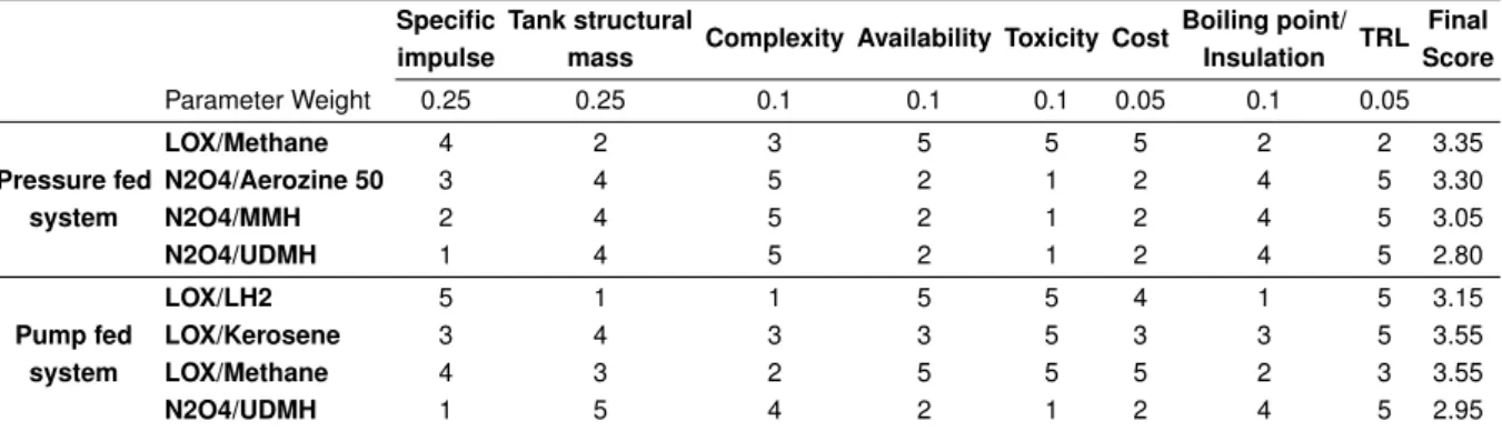
This issue led to the replacement of reliability by TRL as a parameter used in the fuel trade study.
Appendix B
Structural Mass of Various Tank Geometries
Then, using the density of aluminum and the minimum thickness of 0.001 m, together with the area of both ellipsoids and cylinders, the total mass can be determined. Again, the same terms used for the first example are used, but this time the main dimensions of the tank are determined by the total volume of the second stage tank. To determine the cylinder length (Lcyl), inner radius (Rint) and elliptic height c, the following expressions must be solved (considering the fuel tank as inner).
Once again taking the areas of both cylinders and using the Wolfram Alpha online tool to determine the elliptical torus area, the total mass is 31 kg.
Appendix C
Analytical Sizing
Second Stage
Fairing
This is called a forward hull and its height will be equal to the radius of the upper spherical dome. Since this part will not be pressurized, the critical size is the case when the compressive force is maximum. To prevent this, a thickness of 1.3 mm is required, resulting in a maximum axial stress of -23 MPa and a critical buckling stress of -31 MPa.
Upper spherical dome
Bulkhead
In conclusion, the mass of the spherical bulkhead is 21.3 kg, which allows a saving of 44 kg (given the increase in cylinder length) compared to the elliptical bulkhead. Therefore, this was chosen as the final configuration.
Cylinder
Lower spherical dome
First Stage
Interstage
Appendix D
Launch Vehicle Layout
![Figure 2.9: Comparison between theoretical I sp of various propellants. Reproduced from [17].](https://thumb-eu.123doks.com/thumbv2/123dok_br/19768583.0/34.892.214.666.642.961/figure-comparison-theoretical-i-sp-various-propellants-reproduced.webp)