High Speed
Overlock Machine
131M-04 132M-015 133M-04 / TF 134M-04 241M-24 / 25
243M-24 / TF 244M-24 251M-35 251M-55 251H-56
321 C
Instruction Manual
and Parts List
Contents
1 Safety Instructions 1
1.1 Important Safety Instructions 1
1.2 Safe Operation 2
2 Product Description and Machine Specification 3
2.1 Product Description 3
2.2 Machine Specification 4
2.3 Motor, Motor Pulley and Belt 4
3 Mounting and Adjustment Instructions 5
3.1 Table Cut-Out Diagram 5
3.2 Machine Installation 6
3.3 Lubrification and Oil Drainage 8
3.4 Needle Attachment (or Replacement) 9
3.5 Machine Threading 9
3.6 Thread Tension Adjustment 10
3.6.1 Tension Nut Adjustment 10
3.6.2 Needle Thread Control 10
3.6.3 Looper Thread Control 11
3.6.4 Chain Looper Thread Cam Control 11
3.7 Adjusting the Differential Feed Rate 12
3.8 Stitch Length Adjustment 12
3.9 Parts Relation and Timing 13
3.9.1 Needle and Needle Plate 13
3.9.2 Upper Looper (Spreader) and Needle 14
3.9.3 Lower Looper and Needle 14
3.9.4 Upper and Lower Loopers 15
3.9.5 Needle and Needle Guard 15
3.9.6 Chain Looper and Needle 15
4 Maintenance 16
4.1 Machine Head Cleaning 16
4.2 Oil Change and Filter Cleaning 16
6 Parts List 19
6.1 Frame Components 20
6.2 Cloth Plate Components 22
6.3 Cover Components 24
6.4 Main Shaft Components 26
6.5 Needle Bar Components 28
6.6 Thread Guide Components 30
6.7 Upper Looper Components 32
6.8 Lower Looper Components 34
6.9 Front Looper Components 35
6.10 Cam Components 36
6.11 Differential Feed Components 38
6.12 Feed Dog Components 40
6.13 Trimming Components 42
6.14 Presser Foot Components 44
6.15 Lubrication Components 46
6.16 Feed Snap Components 48
6.17 Thread Spool Components 50
6.18 Plate Row Material Components 52
6.19 Accessories 53
7 Gauge Parts List 54
Contents
Safety Instructions
Important Safety 1.1
Instructions Important
• Before running the machine, make sure all relevant safety specifica- tions are adequate to specifica- tions and technical standards in your country.
• The machine should not be run without its safety devices.
• The machine should only be oper- ated by properly trained personnel.
• For your safety, goggles must be used while running the machine.
• Turn off or unplug the machine in the following situations:
• Passing the thread by the nee- dle or replacing the bobbin or looper.
• Replacing the needle, presser foot, throat plate, feed dog and sliding plate.
• When the machine is in main- tenance.
• When the operator is not run- ning the machine.
• In case of lubricant oil contact with the eyes or skin, wash the surface with plenty of icy water.
In case of ingestion, seek medical help immediately.
• Repair, fitting or maintenance should only be performed by properly trained personnel.
• Maintenance and repair on elec- tric equipment should only be made by qualified personnel. If any electric device is damaged, the machine should be immedi- ately stopped.
• Before starting the machine in full running, a test must be conducted to assure that machine and opera- tor are able to perform the task.
• The machine should not be placed next to a sound source as an ultra- sonic welding machine and other equipment.
• The machine should only be run with the proper electric cable and connectors, and also the ad- equate grounding.
• The machine should only be used to sew materials as indicated in its instructions manual, and indi- cations of use should be followed.
Singer will not be held responsible for any damage caused by unau- thorized changes in the product.
When using the machine, basic safety procedures must be followed.
Read with attention all instructions before using the machine.
When using it, understand that all basic safety instructions are not limited to the following items.
Read all instructions,
take care of this
manual, and use it
as reference when
necessary.
• To avoid the risk of electric shock, do not open the motor wiring box and do not touch the components assembled inside the wiring box.
• To avoid injuries do not run the machine without the belt cover or in case any other safety device is removed.
• To avoid possible injuries keep fingers, head, and clothes far from wheel, belt and motor when the machine is running. Nothing should be placed near those parts.
• To avoid injuries never put your fingers next to the loopers when the machine is running.
• The shuttle whirls at high speed while the machine is running. To avoid hand injuries, keep them away from the shuttle while the machine is running. Turn off the machine to replace the bobbin.
• To avoid possible injuries be care- ful when putting down or lifting the machine head.
• To avoid accidents in case of a sudden start of the machine al- ways turn it off when laying it down, or remove the belt cover and the belt.
• If your machine is equipped with a servomotor, it does not make noises while being driven. To avoid a possible accident caused by an unexpected start, bev sure the ma- chine is turned off.
• To avoid electric, do not run the machine without proper ground- ing.
• To minimize the risk of accidents or damages in electric compo- nents caused by electric discharge turn the machine off before un- plugging it.
• Clean the machine periodically.
Safe Operation 1.2
High Speed Overlock Machine
Product Description and Machine Specification
2.1 Product
Description
2.2
2.3
Machine Specification
Motor, Motor Pulley and Belt
• Clutch motor 1/2 HP (400W) high speed (2 poles)
• Belt type M
Model
321C
Needle Thread Gauge [mm]
Stitch width [mm]
Stitch Length [mm]
Differential Presser Height [mm]
Needle Singer Type
Speed [spm]
Usage
131M-04
1 3 -
4.0
3.6 0.7~2.0 5.5
6120-06 75/11 6,000 Three-thread overlock machine
132M-015 1.5 6120-06 65/9 6,000 Three-thread handkerchief edging
(rolled hem) overlock machine
133M-04 / TF 4.0 6120-06 75/11 5,500 Three-thread elastic attaching
overlock machine
134M-04 4.0 6120-06 75/11 6,000 Three-thread back latch overlock
machine 241M-24
2 4 2
4.0
3.6 0.7~2.0 6.0
6120-06 75/11 6,000 Four-thread overlock machine
241M-25 5.0 6120-06 75/11 6,000 Four-thread overlock machine
243M-24 / TF 4.0 6120-06 75/11 5,500 Four-thread elastic attaching
overlock machine
244M-24 4.0 6120-06 75/11 6,000 Four-thread back latch overlock
machine
251M-35
3 5
3.0 5.0 3.6
0.7~2.0 6.0
6120-06 90/14 5,500 Five-thread overlock machine
251M-55 5.0 5.0 3.6 6120-06 90/14 5,500 Five-thread overlock machine
251H-56 5.0 6.0 5.0 6120-06 130/21 5,500 Five-thread heavy duty
overlock machine
Maximum Machine Speed [spm]
Motor Pulley Diameter [mm]
60 Hz 50 Hz
4,500 70 90
4,750 75 95
5,000 80 100
5,250 85 105
5,500 90 110
Mounting and Adjustment Instructions
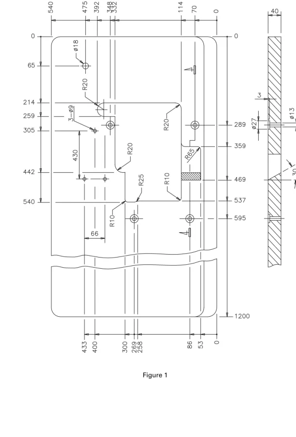
Table Cut-Out 3.1
Diagram
Machine Installation
3.2 Install the machine support compo- nents and the residues cam as indi- cated on figure 2. In case of semi-in- serted assembly the distance from
the needle bed surface to the table top is 100mm. For inserted assem- bly the distance is about 5.0mm.
Figure 2
Machine Installation
Set the machine head on the sup- port base.
Connect the machine wheel to the motor with the belt.
Adjust the belt tension so that there is a gap of about 20 mm when the center of belt is pressured.
Set the belt cover according to fig- ure 4.
Figure 3
Figure 4
Install the friction motor pedal at the right side and the pedal of the presser lifter at the left side.
Be sure the motor is clockwise di- rected, referred to figure 3.
3.2
Lubrication 3.3
and Oil Drainage
As this is a high speed machine, DO NOT run the machine before oiling and assuring the direction of motor rotation.
Important
Remove the oil flow sight win- dow ‘A’ and fill with the lubricant oil (Singer Oil), until the indicator of the oil level is between the two lines of the oil level sight window
‘B’. After that, put back the oil flow window ‘A’ and squeeze it.
When using the machine for the first time, or a machine that has not been used for some time, oil the needle bar top, the guides and loopers before running it.
A new machine should be run at 80% maximum speed on the first four weeks. After this initial cycle,
Figure 5
Figure 6 C
B
replace the oil and from then on the machine can be used at maxi- mum speed.
To preserve the machine, change the oil after four weeks of use. After that the oil must be changed every four months. To change the oil sim- ply remove the screw ‘C’ indicated on figure 6. After draining the oil, replace the screw and complete the machine with new oil.
This machine has an oil filter (fig- ure 6) that must be cleaned every month or changed as needed.
Oil
Oil
A
Machine 3.5
Threading
Refer to the sewing type you need for correct threading. Any incorrect threading may cause thread brake, uneven stitches or skip stitches.
Important
For five thread machine For three / four thread machine
3.4 Needle Attachment (or Replacement)
Use needle Singer 6120-06.
Release screw ‘1’ as indicated on figure 7 and put (or withdraw the old needle).
Insert the needle with the slot turned to the back side and push it up until the bar end. Tighten screw ‘1’.
Figure 7
Figure 8 Figure 9
Thread Tension 3.6
Adjustment
The thread tension should be adjusted according to the type and thickness of cloth, thread, sewing width, stitch length and others. Therefore, the pressure on the Tension Buttons or Thread Guides should be individually adjusted for each case.
Important
3.6.1
Tension Nut Adjustment
The following adjustments are re- lated to figure 10.
Tension Nut 1: controls the needle thread or the left thread in case of two needles.
Tension Nut 2: controls the thread in the right needle.
Tension Nut 3: controls the thread in the right looper
Tension Nut 4: controls the thread in the left looper
Tension Nut 5: controls the thread of the safety stitch.
Figure 10
3.6.2
Needle Thread Control
For all types of stitch 504, 512 or 514, move down the guides ‘1’ and ‘2’.
For the types of stitch 503 and 505, move the guides ‘1’ and ‘2’ to the highest point.
Figure 11
The signal (+) increases the tension in the thread. The signal (-) reduces the
Note
3.6.3
Looper Thread Control
For the type of stitch 512, when Ad- just guide ‘1’ and ‘2’ as follows the looper on the right is at the left far end, adjust ‘1’ and ‘2’ in level with the dotted mark, as on figure 12.
For the type of stitch 503 and 505, move the guides to the lowest point and adjust ‘1’ and ‘2’ in level with the continuous line.
Adjust guide ‘3’ as follows:
• Position ‘A’: for stretchy thread
• Position ‘B’: for seaming and blind stitch hemming
• Position ‘C’: stitch type 512 Adjust guide ‘4’ as follows:
• Position ‘D’: for stretchy thread
• Position ‘E’: for seaming and blind stitch hemming.
Figure 12
3.6.4
Chain Looper Thread Cam Control
When the needle is on high posi- tion, mark ‘A’ must be aligned with the thread guide bracket ‘1’, as shown on figure 13.
Release screw ‘2’ and the thread cam ‘3’. Turn it clockwise for quick release of thread through the cam.
Figure 13
The signal (+) means more thread and (-) means less thread.
Note
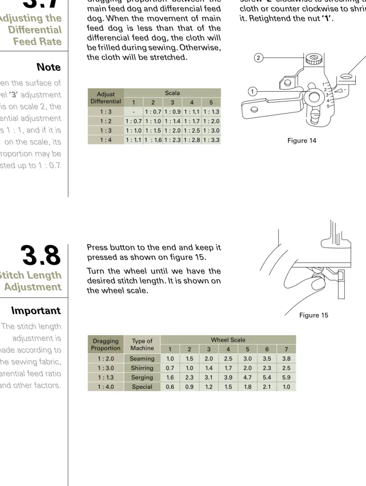
Adjusting the 3.7
Differential Feed Rate
Adjustment of the differential is the dragging proportion between the main feed dog and differencial feed dog. When the movement of main feed dog is less than that of the differencial feed dog, the cloth will be frilled during sewing. Otherwise, the cloth will be stretched.
Stitch Length 3.8
Adjustment
The stitch length adjustment is made according to the sewing fabric, differential feed ratio and other factors.
Important
Press button to the end and keep it pressed as shown on figure 15.
Turn the wheel until we have the desired stitch length. It is shown on the wheel scale.
Figure 15 Figure 14
Release nut ‘1’ on figure 14, and turn screw ‘2’ clockwise to streching the cloth or counter clockwise to shrink it. Retightend the nut ‘1’.
Adjust Differential
Scala
1 2 3 4 5
1 : 3 - 1 : 0.7 1 : 0.9 1 : 1.1 1 : 1.3 1 : 2 1 : 0.7 1 : 1.0 1 : 1.4 1 : 1.7 1 : 2.0 1 : 3 1 : 1.0 1 : 1.5 1 : 2.0 1 : 2.5 1 : 3.0 1 : 4 1 : 1.1 1 : 1.6 1 : 2.3 1 : 2.8 1 : 3.3
When the surface of level ‘3’ adjustment is on scale 2, the differential adjustment is 1 : 1, and if it is on the scale, its proportion may be adjusted up to 1 : 0.7.
Note
Dragging
Proportion Type of Machine
Wheel Scale
1 2 3 4 5 6 7
1 : 2.0 Seaming 1.0 1.5 2.0 2.5 3.0 3.5 3.8 1 : 3.0 Shirring 0.7 1.0 1.4 1.7 2.0 2.3 2.5 1 : 1.3 Serging 1.6 2.3 3.1 3.9 4.7 5.4 5.9 1 : 4.0 Special 0.6 0.9 1.2 1.5 1.8 2.1 1.0
Parts Relation 3.9
and Timing
3.9.1
Needle and Needle Plate
When needle at the highest posi- tion, distance ‘A’ between needle point (the left needle if there are two needles) and needle plate is 9.5 to 9.7 mm for standard adjust- ment, or 10.8 to 11.0 mm for spe- cific cases. Each needle should be centralized over each hole in the needle plate. The right needle must be about 0.2 to 0.3 mm ahead the left needle.
Distance between needle point (the right needle if there are two nee- dles) and the front part of the hole in the needle plate or presser foot is 1.2 mm.
Release screw ‘1’, as shown on fig- ure 16.
Turn the wheel to see if needle is centralized at every hole of the needle plate. Release screw ‘2’ to adjust needle holder.
Turn the wheel to move needle to the highest position and move nee- dle bar until the height is correctly adjusted.
Tighten screws ‘1’ and ‘2’.
Figure 16
Figure 18
Figure 19
3.9.2
Upper Looper (Spreader) and Needle
When the right looper moves to the far left end, distance ‘A’ between the looper point and the center line of the needle is 4.5 to 5.0 mm for one
needle. For two needles, the dis- tance ‘B’ is 5.5 to 6.0 mm from the left needle, as shown on figure 17.
3.9.3
Lower Looper and Needle
When the lower looper moves to the extremly left, the distance ‘A’
between looper point and center line of the needle (left needle, if two needles) is from 3.4 to 3.6 mm, for high lift machines, as shown on figure 18.
When the lower looper moves to the center line of needle (left nee- dle, if two needles), the gap be- tween needle and looper is from 0 to 0.05 mm, as shown on figure 19.
Figure 17
3.9.4
Upper and Lower Loopers
When the upper and lower loopers are crossed, the distance is 0.2 mm for ‘A’ and 0.5 mm for ‘B’, accord- ing figure 20.
Figure 20
3.9.5
Needle and Needle Guard
When the looper point is on the side opposite to the center line of the needle (left needle if there are two needles), space between nee- dle and rear needle guard of ‘A’ is 0 mm. When needle moves to the lowest position, space between needle and front needle guard of
‘B’ is from 0.15 to 0.20 mm, accord- ing to figure 21.
Figure 21
3.9.6
Chain Looper and Needle
The safety looper should be fixed in a position lower than this support.
And when it moves to the left far end, the distance between the loop- er point and the center line of needle is 2.5 mm, according to figure 22.
Figure 22
Maintenance
Machine 4.1
Head Cleaning
Clean the machine head periodi- cally with a dry soft cloth to remove the excess of dust in the head. Do not use any kind of solvent material to clean the surface.
Oil Change and 4.2
Filter Cleaning
If the machine has not been used for a long time, lubricate the superior part of the needle bar, guides and loopers before returning to opera- tion.
Oil should be changed every four months. When changing the oil fol- low instructions on item 3.3.
Oil filter should be cleaned every month or replaced for a new one as necessary. To clean the filter or change the oil, follow instruction in item 3.3.
4.3 Safety Inspection
Frequently check if all safety de- vices are properly installed and adjusted.
Check all screws that fix and hold the machine head that should be properly tight.
Check and be sure the belt is not excessively worn out and see that it has the proper tension.
Check and be sure there is no mo-
tor overheating and be sure that
the cable and electric connector
are not damaged.
Troubleshooting
Problems Possible Causes Possible Solutions
Broken needle
1.Needle installed the wrong way. 1.Install the needle correctly.
2.Wrong kind of needle. 2.Use needle adequate for cloth and thread.
3.Damaged needle. 3.Replace for a new one.
4.Wrong relation with needle guards. 4.Adjust needle guards.
5.Wrong relation with looper. 5.Adjust the looper.
6.Needle is not centralized with the hole at the needle plate or the presser foot.
6.Adjust the needle plate or the presser foot.
Broken thread
1.Low quality thread. 1.Use good quality thread.
2.Thread is thicker than the eye of the needle. 2.Use adequate needle to cloth and thread.
3.Wrong passage of thread. 3.Pass thread correctly.
4.Thread tension too tight. 4.Adjust the thread tension unit.
5.Needle wrongly set. 5.Set needle correctly.
6.Thread stand wrongly set. 6.Set the thread stand correctly.
7.Needle overheating. 7.Fill in silicon oil or adjust needle guards.
8.Tension disk or guides with burrs . 8.Replace the parts.
9.Wrong relation of needle with looper . 9.Adjust the synchronism of needle and looper.
10.Needle, looper, needle plate and guides have burrs. 10.Replace the part.
Failure in stitches
1.Wrong relation of needle with looper. 1.Adjust the relation of needle with looper.
2.Wrong passage of thread. 2.Pass thread correctly.
3.Needle installed the wrong way. 3.Install needle correctly.
4.Inadequate tension of thread. 4.Adjust thread tension button.
5.Point of looper damaged. 5.Replace the part.
6.Needle damaged. 6.Replace for a new needle.
7.Wrong installation of needle guards. 7.Adjust the needle cover.
Skip stitches
1.Wrong threading. 1.Pass thread correctly.
2.Thread is thicker than needle hole. 2.Use proper needle hole for cloth and thread.
3.Wrong thread tension. 3.Adjust the thread tension units.
4.Needle thread is not lubricated. 4.Fill in the silicon oil.
5.Wrong relation of needle with looper. 5.Adjust the needle and looper.
Problems Possible Causes Possible Solutions
Uneven Stitches
1.Wrong threading. 1.Threading correctly.
2.Wrong installation of thread stand. 2.Install thread support correctly.
3.Wrong setting of lower knfe. 3.Adjust lower knife correctly.
4.Knives does not cut perfectly. 4.Adjust or replace knives.
5.Thread guide or tension disc with burrs. 5.Replace the part.
6.Needle point damaged. 6.Replace the needle.
7.Inadequate height of feed dog. 7.Adjust the height of feed dog.
8.Inadequate thread tension. 8.Adjust thread tension.
Puckering
1.Thread tension is too strong. 1.Adjust thread tension.
2.Inadequate pressure on presser foot. 2.Adjust pressure on presser foot.
3.Inadequate height of feed dog. 3.Adjust the height of feed dog.
4.Knives does not cut perfectly. 4.Adjust or replace knives.
5.Differential feed is not correct. 5.Adjust differential feed ratio.
6.Needle is too thick. 6.Use proper needle to cloth and thread.
Poor chain-off stitches
1.Incorrect presser foot. 1.Adjust presser foot correctly.
2.Inadequate synchronism of lopper cam. 2.Adjust looper cam.
3.Chain stitch looper installed wrongly. 3.Adjust looper correctly.
4.Wrong passage of thread. 4.Pass thread correctly.
5.Thread tension inadequate. 5.Adjust thread tension.
6.Wrong relation of needle with looper. 6.Adjust relation of needle with looper.
7.Needle plate or presser foot with burr. 7.Replace the part.
8.Rough thread tension disc. 8.Polish thread tension disc.
Troubleshooting
Parts List
6.1 Frame Components
llMJ---@
r@~ ® ~or
@
Qty
No. Part No. Description 3 4 5
thread thread thread
6.1 Frame Components
1 20101069 Machine frame 1 1 1
2 20112001 Needle thread cover plate 1 1 1
3 P01003 Pin 1 1 1
4 20523003 Oil wick 1 1 1
5 20101003 Needle plate 1 1 1
6 20122002 Rear oil adhesive 1 1 1
7 20122003 Oil seal 1 1 1
8 20112002 Rear cover 1 1 1
9 20122005 Oil cover 1 1 1
10 20101004 Cover 1 1 1
11 20122007 Cover washer 1 1 1
12 P01003 Pin 3 3 3
13 20112003 Oil screen 1 1 1
14 H01003 Snap ring 1 1 1
15 20122008 Oil seal I 2 2 1
16 20122009 Oil seal II 1 1 1
17 20626004 Oil amount adjusting pin 1 1 1
18 20121019 Oil tube 1 1 1
19 20127001 Spring 1 1 1
20 20126001 Pin 2 2 2
21 20121019 Oil tube 1 1 1
22 201S11028 Screw 3 3 3
23 201S11027 Screw 2 2 2
24 201S11029 Screw 1 1 1
25 S10005 Screw M3x3 1 1 1
26 201S11033 Screw 1 1 1
27 201S14002 Screw 1 1 1
28 201S11016 Screw 11 11 11
29 201S12005 Screw 1 1 1
30 201S12006 Screw 1 1 1
31 201S30006 Screw 4 4 4
32 20128023 Washer 4 4 4
33 201S13002 Screw 4 4 4
34 201S11021 Screw 1 1 1
35 201S11039 Screw 1 1 1
36 20101065 Side cover 1 1 1
37 20122041 Side cover pad 1 1 1
Cloth Plate 6.2
Components
Qty
No. Part No. Description 3 4 5
thread thread thread
Cloth Plate 6.2
Components
1 2011207900 Cloth plate 1 1 0
2 20122012 Rubber bushing 1 1 1
3 20122013 Rubber bushing 1 1 1
4 201S30011 Screw 1 1 1
5 20127003 Spring 1 1 1
6 20112011 Cloth plate slider cover 1 1 1
7 20127004 Cloth plate cover spring 1 1 1
8 20111022 Cloth plate lower plate 1 1 0
9 20111003 Washer 1 1 1
10 20112012 Upper looper sealing plate 1 1 1
11 20122015 Upper looper sealing plate washer 1 1 1
12 201S11018 Screw 1 1 1
13 201S11016 Screw 2 2 2
14 201S20003 Screw 1 1 1
15 201S17004 Screw 2 2 2
16 201S16003 Nut 1 1 1
17 201S30007 Screw 1 1 1
18 201S16001 Nut 1 1 1
19 W01005 Washer 3 2 2 2
20 201S11005 Screw 2 2 2
21 201S11037 Screw 3 3 3
22 20128019 Washer 3 3 3
23 2011200500 Cloth plate 0 0 1
24 20111002 Cloth plate lower plate 0 0 1
25 20122011 Rubber bushing 1 1 1
6.3 Cover
Components
Qty
No. Part No. Description 3 4 5
thread thread thread
6.3 Cover Components
1 20111019 Upper cover 1 1 1
2 20122016 Upper cover washer 1 1 1
3 20112080 Thread guide supporter 1 1 1
4 20211001 Belt cover 1 1 1
5 20112014 Thread cover spring 1 1 1
6 20112015 Cloth guide plate 1 1 1
7 20112016 Oil guide II 1 1 1
8 20126003 Pin 1 1 1
9 20112017 Front spring 1 1 1
10 20101067 Front cover 1 1 1
11 20112018 Front cover guard 1 1 0
20112019 Front cover guard 0 0 1
12 20101007 Front cover hinge 1 1 1
13 20126004 Hinge pin 1 1 1
14 20127005 Front cover hinge spring 1 1 1
15 20122017 Front cover hinge washer 1 1 1
16 20137002 Trade mark plate 1 1 1
17 20131064 Oil flow window 2 2 2
18 20112020 Front cover snap guard 1 1 1
19 20112021 Oil guard 1 1 1
20 20122018 Oil level gauge washer 1 1 1
21 20126005 Pin 1 1 1
22 20111005 Oil sight window 1 1 1
23 20111021 Eye Guard 1 1 1
24 20111019 Upper cover 1 1 1
25 201S11024 Screw 3 3 3
26 20313001 Thread guide supporter 1 1 1
27 S01010 Screw 2 2 2
28 H05002 Snap spring 1 1 1
29 201S11036 Screw 4 4 4
30 206S11005 Screw 2 2 2
31 201S11009 Screw 9 9 9
32 201S11018 Screw 2 2 2
33 201S15001 Screw 3 3 3
34 201S11014 Screw 2 2 2
35 201S11038 Screw 3 3 3
36 R03001 Rivet 2 2 2
37 20137005 Machine model plate 1 1 1
Main Shaft 6.4
Components
10
@>---
Qty
No. Part No. Description 3 4 5
thread thread thread
6.4
1 20102001 Main shaft 1 1 12 20111008 Wheel 1 1 1
3 20101008 Rear shaft bearing cover 1 1 1
4 20122019 Washer 1 1 1
5 20128002 Main shaft spring washer 1 1 1
6 20103002 Oil seal 1 1 1
7 O01003 Seal ring 1 1 1
8 B03001 Bearing 2 2 2
9 20125001 Oil pump worm 1 1 1
10 20129001 Snap spring 1 1 1
11 20103003 Main shaft left bushing 1 1 1
12 B04001 Bearing 1 1 1
13 20101009 Bearing cover 1 1 0
20101010 Bearing cover 0 0 1
14 20122020 Bearing cover washer 1 1 1
15 20101044 Pulley 1 1 1
16 20101012 Key 1 1 1
17 20126006 Bulgy pulley shaft 0 0 1
18 30128008 Washer 1 1 0
19 201S11040 Screw 1 1 0
20 201S11034 Screw 1 1 1
21 20128024 Washer 1 1 1
22 201S15004 Screw 2 2 2
23 201S11016 Screw 3 3 3
24 201S14002 Screw 1 1 1
25 201S11012 Screw 3 3 3
26 201S15005 Screw 2 2 2
27 201S15001 Screw 1 1 1
Main Shaft
Components
Needle Bar 6.5
Components
Qty
No. Part No. Description 3 4 5
thread thread thread
Needle Bar 6.5
Components
1 20102002 Needle bar driving frame rock shaft 1 1 1
2 20126007 Eccentric shaft 1 1 1
3 20103004 Needle bar shaft bushing back 1 1 1
4 20108001 Thrust collar 1 1 1
5 20104001 Needle bar driving crank 1 1 1
6 20122022 Oil seal 1 1 1
7 B07006 Needle bearing 1 1 1
8 20128004 Washer ring 1 1 1
9 20126008 Needle bar guide pin 1 1 1
10 20123021 Oil wick 1 1 1
11 20102003 Needle bar rock shaft 1 1 1
12 20103005 Needle bar shaft bearing (left) 1 1 1
13 20122021 Seal ring 2 2 2
14 20103006 Needle bar shaft bearing (right) 1 1 1
15 20108002 Thrust collar 2 2 2
16 20101013 Balance block 1 1 1
17 20104002 Needle bar frame rock shaft crank 0 1 0
20104003 Needle bar frame rock shaft crank 1 0 1
18 20105001 Needle bar connecting rod 1 1 1
19 20126009 Connecting link pin 1 1 1
20 201S12005 Screw 1 1 1
21 20101014 Needle bar guide bracket 1 1 1
22 2010200400 Needle bar 1 1 1
23 20117012 Cat No. 6120-06 Needle 1 2 0
20117013 Cat No. 6120-06 Needle 0 0 2
20117014 Cat No. 6120-06 Needle 0 0 2
24 20123021 Oil wick 1 1 1
25 20121020 Plastic tube 1 1 1
26 20123005 Oil wick 2 2 2
27 20134002 Needle clamp 1 0 0
20134001 Needle clamp 0 1 0
20134003 Needle clamp 0 0 1
20134004 Needle clamp (for thick) 0 0 1
28 201S15003 Thrust collar set screw 2 2 2
29 201S13003 Hexagon socket screw 1 1 1
30 201S30003 Balance block position screw 2 2 2
31 201S14002 Thrust collar set screw 3 3 3
32 201S20006 Needle bar connecting rod set screw 2 2 2
33 201S11026 Screw 1 1 1
34 201S17001 Screw 1 1 1
35 201S17004 Screw 1 1 1
36 S01022 Screw 1 1 1
Thread Guide 6.6
Components
1 20111013 Thread tension nut 3 4 4
20311002 Thread tension nut 3 4 4
2 20111014 Ratchet 3 4 4
3 20127018 Thread tension spring 1 2 2
4 20127019 Thread tension spring 1 1 1
5 20127020 Thread tension spring 1 1 1
6 20111015 Thread tension disc presser 3 4 4
7 20112057 Thread tension disc 6 8 8
Qty
No. Part No. Description 3 4 5
thread thread thread
Qty
No. Part No. Description 3 4 5
thread thread thread
Thread Guide 6.6
Components
13 20111009 Silicon oil box 1 1 1
14 20112022 Oil felt 1 1 1
15 20113005 Thread guide 1 1 1
16 20122023 Silicon oli washer 1 1 1
17 20123006 Oil felt 1 1 1
18 20113006 Tension spring 1 1 1
19 20113007 Thread controller disc holder 1 1 1
20 20127006 Spring 1 1 1
21 20103008 Thread controller disc guide bushing 1 1 1
22 20101015 Throat plate positioning rod 2 2 2
23 20101016 Throat plate bracket 1 1 1
24 20113008 Thread mark guide 1 1 0
20113009 Thread mark guide 0 0 1
25 20117002 Teat needle guard 1 1 1
26 20117003 Front needle guard 1 0 0
20117004 Front needle guard 0 1 0
27 20115001 Needle plate 1 0 0
20115002 Needle plate 0 1 0
20115003 Needle plate 0 0 1
20115004 Needle plate 1 0 0
20115005 Needle plate 0 1 0
20115006 Needle plate 1 0 0
20115007 Needle plate 0 0 1
20115008 Needle plate 0 0 1
20115010 Needle plate 1 0 0
28 20113010 Thread guide 0 0 1
29 20117005 Needle guard I 0 0 1
30 20117006 Needle guard II 0 0 1
31 20101017 Needle guard bracket 1 1 0
20101018 Needle guard bracket 0 0 1
32 20101019 Snap plate 1 1 1
33 20122024 Snap plate washer 1 1 1
34 W01011 Washer 1 1 1
35 201S17005 Throat screw 2 2 2
36 201S11008 Front needle guard screw 1 1 1
37 201S11029 Throat plate bracket screw 2 2 2
38 201S11014 Thread guide holder screw 1 1 1
39 201S11001 Silicon oil box set screw 1 1 1
40 201S20005 Silicon oil box set screw 1 1 1
41 201S11003 Rear needle guard screw 2 2 2
42 201S12009 Needle guard screw 3 3 3
43 201S11009 Thread take up screw 2 2 2
Upper Looper 6.7
Components
Qty
No. Part No. Description 3 4 5
thread thread thread
6.7
1 20105002 Looper link 2 2 22 20126010 Looper link holder 2 2 2
3 20128005 Thickness washer 1 1 1
4 20102006 Upper looper shaft 1 1 1
5 20128007 Big washer 1 1 1
6 20103009 Upper looper shaft rear bushing 1 1 1
7 20103010 Upper looper shaft front bushing 1 1 1
8 20122025 Upper looper shaft oil seal 1 1 1
9 20104004 Upper looper shaft crank 1 1 1
10 20104005 Upper looper shaft bar 1 1 1
11 20126011 Connecting rod shaft pin 1 1 1
12 20112023 Washer 1 1 1
13 20123021 Oil wick 1 1 1
14 20109001 Upper looper slide block 1 1 1
15 20123008 Oil felt 2 2 2
16 20123009 Oil felt 1 1 1
17 20113013 Thread tube 2 2 2
18 20112024 Screen oil plate 1 1 1
19 20112025 Felt plate 1 1 1
20 20112026 Thread holder snap plate 1 1 1
21 20101020 Upper looper shaft slide bar bracket 1 1 1
22 20113014 Thread guide 1 1 1
23 20523003 Oil wick 1 1 1
24 201S11005 Screw 1 1 1
25 20112027 Thread amount regulating plate 1 1 1
26 20113011 Upper looper thread guard 1 1 1
27 20113012 Upper looper shaft thread plate 1 1 1
28 201S17006 Screw 1 1 1
29 201S11007 Upper looper set screw 1 1 1
30 20117007 Upper looper 1 1 1
31 20104006 Upper looper crank 0 1 1
20104007 Upper looper crank 1 0 0
32 201S20006 Screw 8 8 8
33 201S11035 Screw 2 2 2
34 201S12007 Upper looper crank screw 1 1 1
35 20128021 Washer 1 1 1
36 S10005 Link pin set screw 1 1 1
37 201S13003 Hexagon socket screw 3 3 3
38 201S12005 Upper looper shaft screw 1 1 1
39 201S11016 Thread guide screw 3 3 3
40 201S11014 Screw 2 2 2
41 201S11006 Thread guide screw 2 2 2
Upper Looper
Components
Lower Looper 6.8
Components
1 20128009 Washer 1 1 1
2 20128007 Lower looper shaft washer 1 1 1
3 20622019 Oil seal 1 1 1
4 20103011 Lower looper shaft bushing (front) 1 1 1
5 20103015 Lower looper shaft bushing (rear) 1 1 1
6 20104008 Lower looper holder 1 1 0
20104025 Lower looper holder 0 0 1
7 20104009 Lower looper crank 1 1 0
20104010 Lower looper crank 0 0 1
8 20117008 Lower looper 1 1 0
20117009 Lower looper 0 0 1
9 201S11007 Crank screw 0 0 2
10 20113015 Thread guide 1 1 1
11 20113016 Lower looper thread guide 1 1 1
12 20113017 Lower looper thread guide 1 1 1
13 20102007 Lower looper shaft 1 1 0
Qty
No. Part No. Description 3 4 5
thread thread thread
Qty
No. Part No. Description 3 4 5
thread thread thread
Front Looper 6.9
Components
1 20104011 Front looper shaft holder 0 0 1
2 20117010 Front looper 0 0 1
3 20128014 Washer 0 0 1
4 20104012 Front looper crank 0 0 1
5 20609017 Regulating plate 0 0 1
6 20126013 Regulating plate pin 0 0 2
7 20108001 Driving crank holder 0 0 1
8 20103013 Front looper shaft bushing (front) 0 0 1
9 20103014 Front looper shaft bushing (rear) 0 0 1
10 20102009 Front looper shaft 0 0 1
11 20101021 Driving lever 0 0 1
12 20104013 Front looper driving crank 0 0 1
13 20109002 Front looper slide block 0 0 1
6.10 Cam Components
28
~~ ~d . . T-® ~1 17
. . ..
··~
~ 33Qty
No. Part No. Description 3 4 5
thread thread thread
6.10 Cam Components
1 20105003 Horizontal shaft link 0 0 1
2 20124002 Needle bearing 0 0 1
3 20112028 Snap ring 0 0 1
4 20126014 Pin 0 0 1
5 20104014 Horizontal shaft crank 0 0 1
6 20102010 Horizontal shaft 0 0 1
7 20103015 Left horizontal shaft bushing 0 0 1
8 20103016 Right horizontal shaft bushing 0 0 1
9 20122028 Oil seal 0 0 1
10 2011301800 Looper thread take-up cam 0 0 1
11 20113020 Thread guide 0 0 1
12 20113021 Thread guide 0 0 2
13 20112029 Bracket 0 0 1
14 20128015 Flat spring 0 0 1
15 20112030 Thread guide position plate 0 0 1
16 20113022 Thread guide ring 0 0 1
17 20113023 Thread guide 0 0 1
18 20113024 Thread guide 0 0 1
19 20113025 Thread pipe cover 0 0 2
20 20113026 Thread pipe 0 0 1
21 20112031 Bracket 0 0 2
22 20112032 Bracket 0 0 1
23 201S30012 Screw 0 0 1
24 20112033 Tension disc 0 0 2
25 20127007 Spring 0 0 1
26 201S16007 Nut 0 0 1
27 201S17001 Bearing snap ring screw 0 0 2
28 201S14001 Cam set screw 0 0 2
29 201S13003 Crank set screw 0 0 1
30 20128033 Washer 0 0 1
31 201S16002 Nut 0 0 1
32 201S16003 Nut 0 0 1
33 201S11014 Screw 0 0 4
34 201S11001 Thread guide plate screw 0 0 2
35 201S11009 Thread guide plate screw 0 0 2
36 201S20001 Screw 0 0 1
Differential Feed 6.11
Components
32
Qty
No. Part No. Description 3 4 5
thread thread thread
Differential Feed 6.11
Components
1 20102011 Stitch length regulating shaft 1 1 1
2 20127008 Spring 1 1 1
3 O01016 Oil washer 1 1 1
4 2011000100 Stitch length regulation cam assembly 1 1 1
5 20109004 Stitch length regulating block 1 1 1
6 20127009 Stitch length regulating block spring 2 2 2
7 20110002 Stitch length cam 1 1 1
8 20112034 Stitch length regulating plate 1 1 1
9 20110003 Feed length cam 1 1 1
10 20112035 Feed cam spring 1 1 1
11 P01004 Feed cam pin 1 1 1
12 20105004 Feed link 1 1 1
13 B07007 Feed rod rolling pin bearing 1 1 1
14 20104015 Feed crank 1 1 1
15 20105005 Differential link 1 1 1
16 20104016 Differential crank 1 1 1
17 20102012 Differential shaft 1 1 1
18 20103017 Differential shaft bearing 1 1 1
19 20122029 Oil seal 1 1 1
20 20108005 Thrust collar 1 1 1
21 20127010 Spring 1 1 1
22 201S16008 Washer 1 1 1
23 20109005 Regulating block 1 1 1
24 20128027 Washer 1 1 1
25 20110004 Feed cam 1 1 0
26 20128028 Washer 1 1 1
27 20112036 Differential regulation holder 1 1 1
28 201S30013 Regulating screw 1 1 1
29 20127011 Regulating screw spring 1 1 1
30 20112037 Differential regulating link 1 1 1
31 2010402300 Crank link cam 0 0 1
32 201S20008 Differential link screw 1 1 1
33 201S13003 Differential crank screw 2 2 2
34 201S12002 Thrust collar set screw 1 1 1
35 20128024 Washer 1 1 1
36 W01006 Washer 2 2 2
37 201S11016 Differential position screw 1 1 1
38 201S11005 Spring screw 1 1 1
39 201S30005 Differential regulating screw 1 1 1
40 201S11018 Differential regulating screw 2 2 2
41 201S14002 Screw 4 4 4
42 201S12005 Screw 1 1 1
6.12 Feed Dog
Components
Qty
No. Part No. Description 3 4 5
thread thread thread
6.12 Feed Dog Components
1 20109006 Main feed dog link plate 1 1 1
2 20106001 Main feed dog bar 1 1 1
3 20106002 Differential feed dog bar 1 1 1
4 20109007 Feed dog lift slide block 1 1 1
5 20109008 Differential feed slide block 1 1 1
6 20102013 Slide block eccentric shaft 1 1 1
7 20112038 Slide block eccentric washer 1 1 1
8 20103018 Slide block eccentric shaft bushing 1 1 1
9 20102014 Feed shaft 1 1 1
10 20103019 Feed shaft bushing (left) 1 1 1
11 20103020 Feed shaft bushing (right) 1 1 1
12 20104017 Feed regulating crank 1 1 1
13 20128021 Washer 1 1 1
14 20105006 Main feed dog bar link 1 1 1
15 20103021 Main feed dog bar link bushing 1 1 1
16 20128029 Washer 1 1 1
17 20112039 Crank slide block cover 1 1 1
18 20109010 Crank slide block 1 1 1
19 20104018 Feed regulating crank 1 1 1
20 20105007 Differential feed dog bar link 1 1 1
21 20103022 Differential feed dog bar link bushing 1 1 1
22 20128030 Washer 2 2 2
23 20101023 Screw oil plate 1 1 1
24 20109011 Feed dog carrier connection rod 1 1 1
25 20122030 Sealing connecting ring 1 1 1
26 20122031 Adjustable oil seal 2 2 2
27 20109012 Sealing connecting rod 1 1 1
28 20102015 Feed dog link eccentric shaft 1 1 1
29 2011401700 Feed dog complete set 1 1 0
2011401800 Feed dog complete set 1 0 0
2011401900 Feed dog complete set 0 0 1
2011402000 Feed dog complete set 0 0 1
30 201S15003 Thrust collar set screw 2 2 2
31 20108002 Thrust collar 1 1 1
32 201S12002 Screw 1 1 1
33 201S11003 Screw 1 1 1
34 201S11012 Screw 1 1 1
35 201S11038 Screw 2 2 2
36 201S12003 Screw 1 1 1
37 201S12004 Screw 1 1 1
38 201S17003 Screw 1 1 1
39 201S13003 Crank screw 2 2 2
40 201S11005 Crank 4 4 4
6.13 Trimming
Components
Qty
No. Part No. Description 3 4 5
thread thread thread
6.13 Trimming Components
1 20105008 Upper knife drive connecting link 1 1 1
2 20104019 Upper knife crank 1 1 0
20104020 Upper knife crank 0 0 1
3 20126015 Crank pin 1 1 1
4 20102017 Upper knife frame rock shaft 1 1 1
5 20103023 Bushing (left) 1 1 1
6 20103024 Bushing (right) 1 1 1
7 20128031 Washer 1 1 1
8 20101024 Upper knife holder 1 1 0
20101025 Upper knife holder 0 0 1
20101053 Upper knife holder 0 0 1
9 20108002 Thrust collar 1 1 1
10 20126016 Upper knife holder pin 1 1 1
11 20119001 Upper knife 1 1 1
20119005 Upper knife 0 0 1
12 20128020 Washer 1 1 1
13 20102018 Lower knife holder 1 1 0
20102019 Lower knife holder 0 0 1
20102023 Lower knife holder 1 1 0
14 20103025 Lower knife holder bushing 1 1 1
15 20127012 Lower knife holder spring 1 1 1
16 20112040 Lower knife holder plate 1 1 1
17 20119002 Lower knife 1 1 1
20119006 Lower knife 0 0 1
18 20101026 Lower knife holder lock plate 1 1 1
19 201S15003 Thrust collar set screw 2 2 2
20 201S13003 Upper knife crank set screw 1 1 1
21 201S12005 Upper knife crank pin screw 2 2 2
22 201S20006 Connecting link screw 2 2 2
23 201S11022 Upper knife holder screw 2 2 2
24 201S12001 Upper knife screw 1 1 1
25 201S11017 Screw 1 1 1
26 201S11012 Screw 1 1 1
27 201S16001 Washer 1 1 1
28 20122038 Oil seal 1 1 1
29 201S11015 Lower knife holder screw 2 2 2
30 W01006 Washer 1 1 0
20128025 Washer 0 0 1
31 20628014 Washer 1 1 1
Presser Foot 6.14
Components
Qty
No. Part No. Description 3 4 5
thread thread thread
Presser Foot 6.14
Components
6 20108006 Thrust collar 1 1 1
7 20127013 Presser foot lifting spring 1 1 1
8 20104021 Presser foot crank 1 1 1
9 20112041 Presser foot lifting lever 1 1 1
10 20126018 Lever hook 1 1 1
11 20127014 Spring 1 1 1
12 20119003 Thread cutting knife 1 1 1
13 20102021 Presser bar 1 1 1
14 20127015 Presser bar spring 1 1 1
15 201S30014 Presser bar screw 1 1 1
16 203S20001 Screw 1 1 1
17 20611006 Presser bar shockproof block 1 1 1
18 20112074 Presser foot lifting handle 1 1 1
19 20627010 Presser foot lifting handle spring 1 1 1
20 20101052 Presser foot lifting handle link 1 1 1
21 30122018 Washer 1 1 1
22 20612031 Presser foot corner plate 1 1 1
23 20127016 Presser foot spring 0 0 1
24 20112042 Presser foot holder connection plate 1 1 0
25 206S20007 Screw 1 1 1
26 S02003 Screw 2 2 2
27 20327001 Presser foot lifting spring 1 1 1
28 20112045 Presser foot holder cover 1 1 1
29 20116001 Presser foot complete 1 0 0
20116002 Presser foot complete 0 1 0
20116003 Presser foot complete 0 0 1
20116006 Presser foot complete 1 0 0
20116007 Presser foot complete 0 0 1
20516015 Presser foot complete 0 0 1
20116004 Presser foot complete 1 0 0
20116005 Presser foot complete 0 1 0
30 20312001 Presser foot lifting handle 1 1 1
31 20326001 Presser foot lifting annul 1 1 1
32 20312002 Presser foot lifting handle bracket 1 1 1
33 20103028 Presser bar bushing 1 1 1
34 20327002 Presser foot lifting spring 1 1 1
35 P03028 Pin 1 1 1
36 201S20004 Set screw 1 1 1
37 201S30020 Lifting handle screw 1 1 1
38 201S11005 Screw 3 3 3
39 201S12007 Crank set screw 1 1 1
40 S10005 Snap washer screw 3 3 3
Lubrication 6.15
Components
Qty
No. Part No. Description 3 4 5
thread thread thread
1 20120001 Oil pump complete 1 1 1
2 201S11025 Oil pump screw 2 2 2
3 201S11019 Oil pan magnet cover screw 1 1 1
4 201S11031 Oil pan screw 1 1 1
5 10131001 Oil pan magnet 1 1 1
6 20112050 Oil pan magnet cover 1 1 1
7 20101035 Oil pan 1 1 1
8 20122035 Oil pan washer 1 1 1
9 20122036 Oil seal 1 1 1
10 20136001 Oil filter 1 1 1
11 20121013 Oil filter joint 1 1 1
12 20101068 Oil filter cover 1 1 1
13 20322004 Oil filter cover seal ring 1 1 1
14 001015 Oil filter cover seal ring 1 1 1
15 2032100400 Tube 1 1 1
16 20136002 Oil tube joint I 1 1 1
17 20136003 Oil tube joint II 1 1 1
18 30129003 Oil tube shape ring 1 1 1
19 20301006 Lubricate bushing 1 1 1
20 20321002 Upper drain pipe 1 1 1
21 20321003 Lower drain pipe 1 1 1
22 203S30004 Screw 1 1 1
23 20311005 Oil show bracket 1 1 1
24 20311006 Oil show cleaner link 1 1 1
25 20312003 Oil show cleaner guard 1 1 1
26 20311008 Oil dial 1 1 1
27 203S30003 Screw 1 1 1
28 201S30004 Screw 1 1 1
29 201S11014 Screw 2 2 2
Lubrication 6.15
Components
6.16 Feed Snap Components
15
6
Qty
No. Part No. Description 3 4 5
thread thread thread
1 20123012 Oil seal 1 1 1
2 20101037 Needle cooler 1 1 0
20101038 Needle cooler 0 0 1
3 20121019 Oil tube 1 1 1
4 20123021 Oil wick 1 1 1
5 20111011 Silicon oil box cover (Lower) 1 1 1
6 20111012 Silicon oil box (Lower) 1 1 1
7 20123014 Oil felt 1 1 0
20123015 Oil felt 0 0 1
8 20123021 Oil wick 1 1 1
9 20112051 Cloth guide holder 1 1 1
10 20112052 Hinge plate 1 1 1
11 20123017 Oil felt block 1 1 1
12 20126020 Hinge pin 1 1 1
13 20112053 Hinge spring 1 1 1
14 20112054 Snap plate 1 1 0
20112055 Snap plate 0 0 1
20112071 Snap plate 1 1 0
15 20112056 Snap plate bracket 1 1 1
16 201S11009 Screw 1 1 1
17 20128020 Washer 3 3 3
18 201S11011 Hinge spring screw 1 1 1
19 201S12001 Hinge screw 2 2 2
20 201S16003 Nut 1 1 1
21 201S11016 Screw 1 1 1
22 201S11018 Needle cooler screw 3 3 3
23 201S20002 Screw 1 1 1
24 20128027 Washer 1 1 1
25 20129002 Oil tube shape ring 2 2 2
6.16 Feed Snap
Components
Thread Spool 6.17
Components
~
30
13f---~l)
8 ) - - - { g
sf---1
10)----~~_d ~~""' 7 f---'~=r"""'/
281)---~4
6
2 r---1
Qty
No. Part No. Description 3 4 5
thread thread thread
1 20131001 Upper thread column 1 1 1
2 20131002 Lower thread column 1 1 1
3 20131003 Bushing 1 1 1
4 20131004 Thread spool tray bracket (lower) 1 0 1
5 20131005 Thread guide hook 2 4 4
6 20131006 Spool pin 3 4 5
7 20131007 Spool tray 3 4 5
8 20131008 Spool retainer 3 4 5
9 20131009 Clamp plate 1 1 1
10 20131010 Spool tray cushion 3 4 5
11 20131011 Thread guide connecting bar 1 1 1
12 20131012 Thread guide joint 1 1 1
14 20131014 Thread guide bar 1 1 1
15 20131015 Thread spool tray bracket (upper) 1 0 1
16 20131016 Thread spool tray bracket (upper) 0 2 1
17 20131017 Thread spool tray bracket (lower) 0 2 1
18 20131018 Thread guide hook 3 4 5
19 20131019 Rubber seal 1 1 1
20 20131020 Thread guide hook screw 2 4 4
21 201S16006 Thread guide hook nut 2 4 4
22 20128016 Thread guide washer 4 4 4
23 20131021 Clamp plate screw 3 3 3
25 201S16004 Nut 8 8 8
26 20128025 Lower washer 2 2 2
27 201S16005 Nut 1 1 1
28 20128018 Washer 4 4 4
Thread Spool 6.17
Components
6.18 Plate Row Material Components
1 20131025 Machine support plate 1 1 1
2 20131026 Support shockproof cushion 3 3 3
3 20131027 Screw 4 4 4
4 20131028 Bolt 4 4 4
5 20131029 Washer 12 12 12
Qty
No. Part No. Description 3 4 5
thread thread thread
Accessories 6.19
1 20131036 Dust cover 1 1 1
2 20131037 Oil can 1 1 1
3 20131038 Notes oil 1 1 1
4 20131039 Funnel 1 1 1
5 20131040 Oil can/50cc 1 1 1
6 20131041 Spanner 1 1 1
7 20131042 Spanner 1 1 1
8 20131043 Spanner 1 1 1
9 20131044 Inner-hexagon screw driver 1 1 1
10 20131045 Inner-hexagon screw driver 1 1 1
11 20131046 Inner-hexagon screw driver 1 1 1
13 20131048 Allen Key Driver 2 2 2
14 20131049 Screw driver 1 1 1
Qty
No. Part No. Description 3 4 5
thread thread thread 2
Machine Model Needle
Cramp Washer Crank Lower Looper
Crank Needle
321C-132M-015 20134002 20128006 20104003 20104009 6120-06 65/9 321C-131M-04 20134002 20128006 20104003 20104009 6120-06 75/11 321C-133M-04/TF 20134002 20128006 20104003 20104009 6120-06 75/11 321C-134M-04 20134002 20128006 20104003 20104009 6120-06 75/11 321C-241M-24 20134001 20128005 20104002 20104009 6120-06 75/11 321C-241M-25 20134001 20128035 20104002 20104009 6120-06 75/11 321C-243M-24/TF 20134001 20128005 20104002 20104009 6120-06 75/11 321C-244M-24 20134001 20128005 20104002 20104010 6120-06 75/11 321C-251M-35 20134003 20128005 20104002 20104010 6120-06 90/14 321C-251M-55 20134004 20128005 20104002 20104010 6120-06 90/14 321C-251H-56 20134004 20128005 20104002 20104010 6120-06 132/21
Machine Model Needle Gauge Needle Plate Feed Dog
Complete Presser Foot
Complete Upper Looper
Needle
Gauge Overedge Width
321C-132M-015 0 1,5 20115006 2011401800 20116006 20117007
321C-131M-04 0 4 20115001 2011401700 20116001 20117007
321C-133M-04/TF 0 4 20115004 2011402100 20116004 20117007
321C-134M-04 0 4 20115001 2011401700 20116004 20117007
321C-241M-24 2 4 20115002 2011401700 20116002 20117007
321C-241M-25 2 5 20115010 2011402200 20116008 20117007
321C-243M-24/TF 2 4 20115005 2011402100 20116005 20117007
321C-244M-24 2 4 20115002 2011401700 20116002 20117007
321C-251M-35 3 5 20115003 2011401900 20116003 20117007
321C-251M-55 5 5 20115008 2011401900 20116007 20117007
321C-251H-56 5 6 20115007 2011402000 20116015 20117007