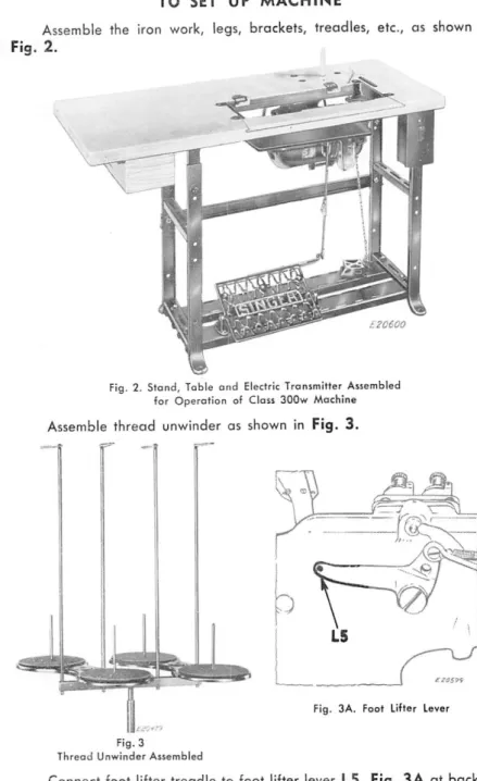
The maximum speed recommended for these machines is 4000 R.P.M., depending on the nature of the work. For the first few days the speed of the machines should not exceed 3500 R.P.M. not exceed, after which they can be driven at their maximum speed. First set right-hand hanger B as close as possible to the cut-out side, level with table as in Fig.
When necessary, to level the machine, use four felt caps A on bottom pins, OS shown in fig. The machine has an efficient automatic quoting system consisting of a hollow arm shaft and a hollow shaft that act as oil reservoirs and supply the required amount of oil to all main bearings when the machine is in operation. NOTE: It is not necessary to remove the work plate when first servicing or subsequent oiling of the machine.
NOTE: To change the stitch formation from a short needle loop to a long needle loop, decrease the tension on the needle threads and pass both hook threads over one arm of the thread shown in fig. The size of the needle to be used is determined by the size of the thread which must pass freely through the eye of the needle. Rough or uneven thread or thread that passes through the eye of the needle with difficulty will interfere with the correct operation of the machine.
24 on the face of the arm indicates the length of stitch the machine is ready to make when the piston L, fig.
MENINNOTCH, TWIST CLOCKWISE ^ TURN
The lift of the vibrating and lifting thrusters is controlled by adjustable N eccentrics. Turn the balance wheel until the feed press is down, loosen two locking screws I and two clamping screws O, hold the screwdriver at the point of the adjusting disc P and turn the balance wheel as shown in Fig. 26, for the required amount of lift. Loosen two U-clamp screws, Fig. 27, turn the fastening of the shaft of the lifting rock T, Fig. 27 up or down until each presser is required to be raised. To adjust, loosen two retaining screws R, Fig. 27 with no more than a half turn of the screwdriver.
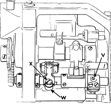
Make sure that the feed lifter shaft lead screw V, Figure 28, properly engages the point of the shaft and that the feed lifter linkage slot engages. If adjustment is necessary, loosen the clamping screw X, move the feed lift link to the correct position, check that it is not side bound, then tighten the clamping screw X firmly. Adjustment to set the feed rod to the correct height. To adjust the feeder laterally so that the needles enter the center of the needle holes, loosen the push ring screws.
When the feed dog is correctly adjusted, place the pressure collars in the correct position and tighten the screws. TO MOVE THE CONVEYOR FORWARD AND BACKWARD IN RELATION TO THE SLOPES IN THE THROAT PLATE To move the conveyor in the feeding direction after positioning the conveyor sideways relative to the needles, set the conveyor eccentrically C2, fig. Turn the adjusting screws B2 and the two clamping screws E2. into the crankshaft of the driving rock shaft and move the input rocker arm Z to the desired position, then tighten the two clamping screws E2 securely.
When the conveyor is in the highest position during the transport stroke, the tines should extend approximately the full depth above the throat plate. 34 and loosen the conveyor clamping screw G2 and nut L5 slightly, then set the conveyor to the correct height, turn the jack H2 counterclockwise and tap the conveyor down to lower it, or turn the adjusting screw H2 clockwise and tap the feed dog to raise it. 36 and move the food lift eccentrically forward to allow the food dog to come up or back sooner for later.
When the carrier is in its highest position, the top of the teeth should be parallel with the upper surface of the neck plate and protrude the full depth of the teeth above the neck plate, then tighten the screws securely at J2. See that the needles are properly aligned with the needle holes in the vibrating press and conveyor. Continue to hold the cutting frame of the needle bar as you place needles into the needle holes of the previously positioned conveyor.
CAUTION: Tighten the K2 screws firmly before releasing the pressure on the rocker frame of the needle bar against the drive arm. 43 and move the loop holder until the loop point is on the center line of its needle, then tighten the loop holder clamping nut S2 firmly.

When needles are in this po
To check the position of the spreader in the feed direction, turn the balance wheel towards you until the needle bar is on its downward stroke and the tips of needles have dropped to the same level as the top of the lucerne blade, as shown in Fig. 47 and right side of rock axis Y2 should be 1/4 inch when ball pin A3 is in horizontal position.
LOOSEN SCREWS E3
REMOVE BRACKET WITH SHAFT C3 AND DRIVE PIN D3
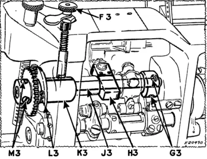
Loosen screws in right-loop rocker bushing G3 and pull out left-loop rocker bushing K3 and shaft, keeping locking pin F3 out of joint while removing bushing K3. To remove push rod spring arm fulcrum E4, loosen two push rod spring arm fulcrum retaining screws F4. CAUTION: When reassembling the push rod spring arm full curve, make sure screws F4 are seated correctly on the flat part of the fulcrum shaft to accurately position the fulcrum.
54 is usually installed with the bottom end of the shot 1/2 inch below the bottom of the mount. Depending on the type of material, the length of the stitch, etc. it is necessary to move the needle thread take-up L4 upwards for a larger needle loop and more pulling force when forming stitches on heavier materials. For average material and sewing conditions, it is advisable to position the bottom edge or thread loop check edge approximately 1/8 inch above the top of the rock frame of the needle bar J4, as shown in Fig.
Move the loop setting eye K4 slightly upwards for heavier degrees of work and downwards from the position given above for lighter work and shorter stitches - the stitch setting and thread pulling should take place at the upward stroke of the needle bar. The collet eccentric is not tarnished and allows timing on the main shaft to suit the job. Loosen the locking screw N4, fig.
56 and turn collar M4 counterclockwise, or turn it clockwise to shorten the holding time, then tighten locking screw N4 securely to prevent collar M4.
TIBHTEN N4
LOOSEN SCREIN 3. TIGHTEN
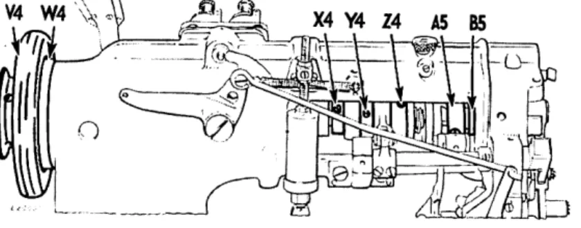
Loosen the screw in the oil crank B5, two screws in the eccentric needle vibrating AS, two screws in the eccentric lifting device Z4, collar Y4 and screws X4 in the eccentric drive of the pliers. 60 (these screws are accessible through the hole in the casting), slide the pulley belt off the bed axle and remove it through the pulley bearing hole. Then remove the arm shaft from the end of the pulley. 62, eccentric looper thread take-up J5, eccentric feed drive H5 and looper-toggle drive crank G5. Then remove the bed axle from the pulley end of the machine, leaving the pulley on the axle for easier handling.