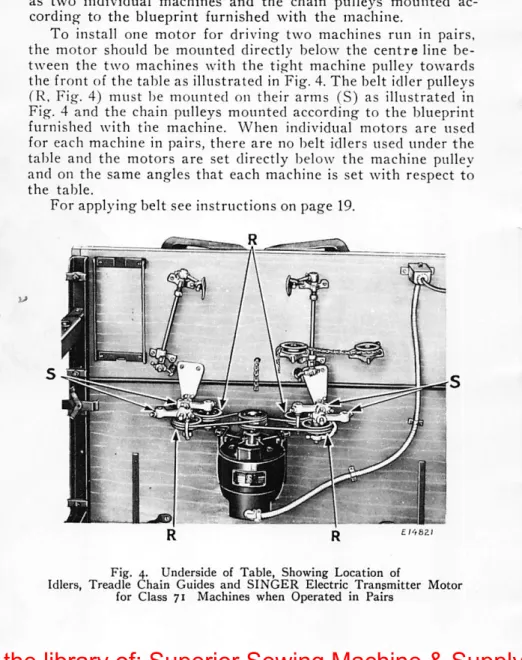
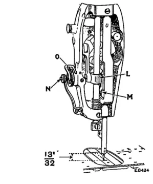
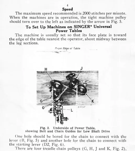
Two belt holes (O, Fig. 2) must be drilled in the table directly below the tight machine pulley according to the location indicated by the blueprint supplied with the machine and the belt pulley (L, Fig. 2) mounted on the bottom of the table directly below these two holes (O). Reach under the bed of the machine with the thumb and index finger of the left hand, open the bobbin case latch (B, Fig. 13) with the index finger and remove the bobbin case. Release the latch, rotate the open end of the bobbin case downwards and the bobbin will drop out.
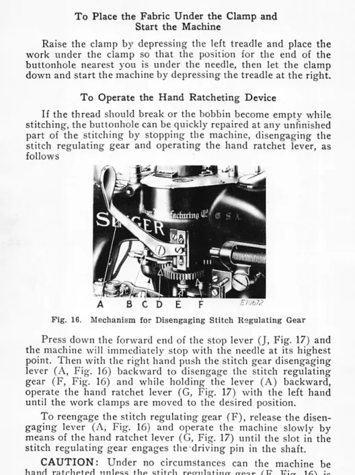
After threading', take the bobbin case by the latch (B, fig. 13) while holding it between the thumb and forefinger of the left hand. Place the spool housing on the center pin (A, Fig. 13) of the shuttle housing with the locating finger opposite the notch in the top of the shuttle barrel. Depress the front end of the stop lever (J, Fig. 17) and the machine will immediately stop with the needle at its highest point.
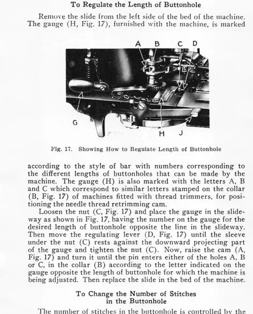
Now lift the comb (A, fig. 17) and turn it until the pin enters one of the holes A, B or C, in the collar (B) according to the letter indicated on the gauge opposite the length of the buttonhole. the machine is adjusted. The number of stitches in the buttonhole is controlled by the stitch adjustment device (F, fig. 16) on the right side of the machine. When making purl buttonholes, the tension on the upper thread must be strong enough to pull the purl evenly to the top of the buttonhole.
The amount of cutting space between the stitching lines is adjusted by the screw (E, Fig. 7) in the slot in the machine bed. If the knife is cut too close to the left side of the buttonhole, the needle bar frame frame must be adjusted to throw the needle a little more to the left. Whenever the arm shaft is turned by hand, it must turn in the direction of the arrow shown in Fig.
INSTRUCTIONS
ADJUSTERS AND MECHANICS
Imperfect stitching, particularly distortion of the barring
Misalignment of stitching with buttonhole cutting knife
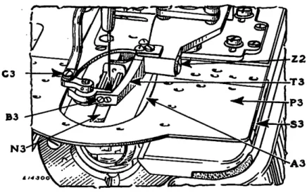
If the locking plate (F3) is not set correctly, it will cause the first locking stitch to be made too far to the left of the first row of side stitches, or the last locking stitch to be made too far to the right of the second row of side stitches. A very small movement of the locking trigger point changes the width of the locking seams significantly. To increase the width of the locking seams, turn the taut machine pulley by hand until the locking release point (£3.
Turn the adjusting screw until there is very little play in the locking slide and then turn the adjusting screw inward against the end of the adjusting screw. To decrease the width of the blocking stitches, increase the lockout point (E3) and then turn the adjustment screw -(T2) to the desired position so that it locates the adjustment screw (U2) and holds the adjustment during adjustment. If you want to stop the machine later, move the switch-off point (E2) to the rear and then tighten the two adjustment screws.
When changing blades, first place the clamping blade in position adjacent to the clamp control, then apply the cutting blade and securely fasten both blades in position with the screw, being careful to position the clamping blade about an inch in front of the cutting blade. When the clamp control is in position on the machine, the trailing edge of the cutting blade should be flush with the front edge of the slot in the clamp control. The cutting blade can be placed in this position by loosening the two screws (A, Fig. 5) and moving the clamp arm forward or backward as may be required.
Lower the cutting blade as far as possible and align it straight, then fix it securely in place using the two screws (X2). The tension on the stop motion locking rod (F, Fig. 26) should be just sufficient to prevent this rod from springing out of the notch in the stop cam and strong enough to slow the movement of the arm shaft before it finally stops the machine. thus minimizing the possibility of breaking the stop cam gear spring. How to Remove and Replace the Stop Cam Gear Spring In the case of the stop cam gear spring which is trapped in the stop.
To remove the spring from the stop cam gear, remove the three screws securing the cover to the stop cam gear and then remove the cover. Place the new spring in the stop cam gear position, inserting the ends of the spring first. Then replace the cover on the stop cam gear and secure it securely in position with the.
The clamp lock is designed to prevent the work clamp from lifting while the buttonhole is being stitched. To change the timing of the belt shifter, loosen the two set screws in the disc (G4) and rotate the disc forward to make the band shifter turn earlier or backward to make it turn later, then tighten the two set screws. Clamp the knife in the holder as shown in the illustration and firmly tighten the clamping screw "D".
Start the grinder and turn the adjustment screw "H" to adjust the cutting edge of the blade so that it barely brushes against the wheel while moving the sliding bracket "J" once to the right and to the left. If more than a small portion of the edge is ground off in one pass, the blade's temperature may decrease until it does. It will then be necessary to adjust the position of the tower "E" to the angle of the tower.
BUY PARTS AND