Carlos Brito, the person who guided me through the antenna fabrication process and took some of his time to explain the whole process for my lighting. To function properly, antennas must be resistant to the electromagnetic influence of the human body.
Glossary
Introduction
Background and Motivation
For example, wireless medical sensor technologies are of great importance for health monitoring [17] [5], since physiological data can be extracted from the sensors, which are placed in the human body, and can be useful to the doctor anytime and anywhere. . The antennas approached in this thesis are designed to operate in the ISM band. center frequencies, 2.45 GHz and 5.8 GHz), defined by article 5, footnote 5.150, of the International Telecommunications Union (ITU) Radio Regulations [24], and in the UWB band (frequency range from 3.1 GHz to 10.6 GHz, according the European UWB Radio Regulations and Standards, [18]).
![Figure 1.1: Body-centric communications, retrieved from [48].](https://thumb-eu.123doks.com/thumbv2/123dok_br/19768800.0/22.892.176.727.104.523/figure-1-body-centric-communications-retrieved-from-48.webp)
Objectives
Selection and dielectric characterization (electrical conductivity, loss tangent, relative dielectric permittivity) of conductive and substrate materials;. Evaluation of antenna performance when placed on a human limb is achieved using numerical phantoms.
Dissertation Organization and Contents
The simulation process is expected to obtain results regarding the critical parameters of the antennas, to verify their robustness against the electromagnetic influence of human body tissues. Regarding the measurements, it is expected that only the influence of the human body on the |S11|parameter of the antennas and their working bands is evaluated.
Antennas in the Vicinity of the Human Body
Body Centric Wireless Communications
Also, reflections often occur, derived from natural movements, such as swinging arms or legs [11] [25]. The measurement setup can be achieved by using phantoms, as they serve as a good model of the human body, by simulating its main biological characteristics, both numerically and physically.
Modeling of the Human Body
- Phantoms
In [30], simple multi-layered and frequency-dependent structures of the human body were considered, which are shown in Figure 2.1. The effect of the elliptical and flat model on the antenna impedance bandwidth is very similar and the simulated results predict well the behavior of the antenna, in the vicinity of the human body.
![Figure 2.1: Simplified models used for simulation, retrieved from [30].](https://thumb-eu.123doks.com/thumbv2/123dok_br/19768800.0/27.892.154.733.532.755/figure-simplified-models-used-simulation-retrieved-from-30.webp)
Antennas Operating in the Vicinity of the Human Body
- Single-band Antennas
- Dual-band Antennas
- UWB Antennas
The geometry of the proposed antenna is based on [8], and is intended to be in the vicinity of the. The significant effect in the behavior of the antenna when in the presence of the models of the. After the simulations, the behavior of the antenna was evaluated in the laboratory, in both free space and next to the human body situations.
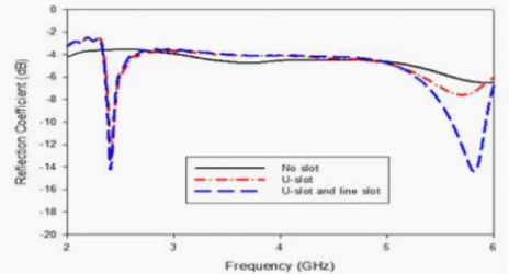
By the same logic, the current concentration observed in Figure 2.11(b) at the edges of the line slot explains the improvement detected in the reflection coefficient at 5.8 GHz. The next step was to evaluate the antenna's behavior in the presence of a human user. An elliptically simplified model of a human arm was found to be perfectly able to predict the performance of the antenna in close proximity to a human user.
Design of a dual-band antenna
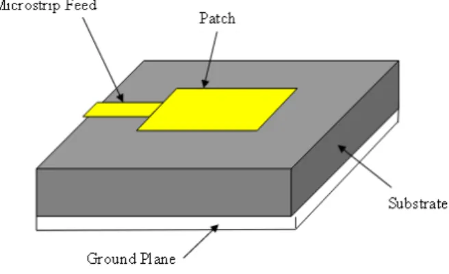
Microstrip Patch Antennas
- Return Loss
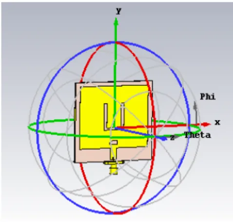
- Radiation Pattern
- Efficiency of an Antenna
3.1) wherefc is the operating frequency, cthe speed of an EM wave in vacuum, Lthe length of the patch antenna and εr the permittivity of the dielectric circuit board (substrate). First, the length L must be approximately half the wavelength, so the antenna is resonant [68]. The fringe fields between the perimeter of the patch and the ground plane are responsible for making the antenna radiate.
Finally, the widthW of the patch antenna is also of great importance, because it can directly influence the input impedance, the radiation pattern and even the bandwidth [68] [49]. The efficiency of an antenna can simply be expressed as the ratio of the power supplied to it to the power radiated by the antenna [10]. There are various factors that can also contribute to the reduction of the (total) efficiency of an antenna.
Design of a Dual-Band Antenna
- Simulation results
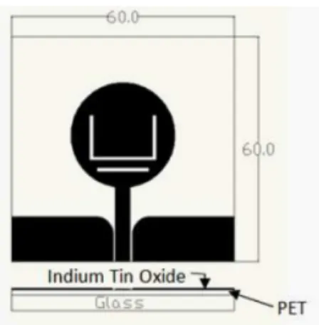
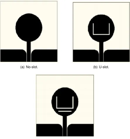
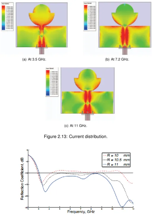
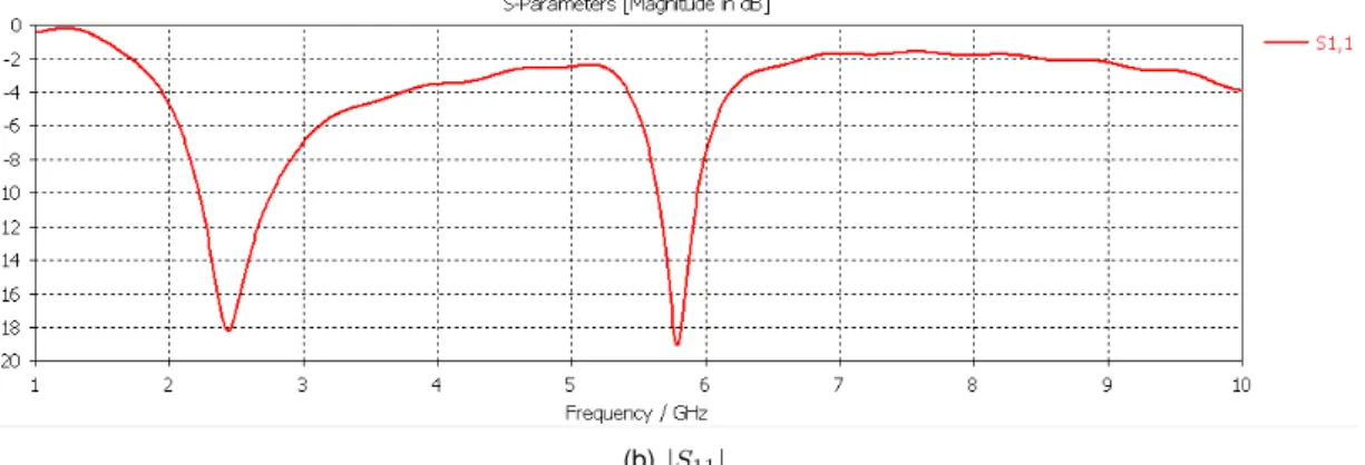
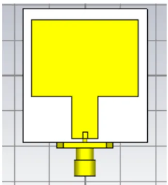
The low dielectric constant and dielectric loss are also suitable for the subsequent development of the antenna. With the selected substrate, you proceed to the next step: the dimensioning of the patch. The rectangular patch was first parameterized to operate at 2.45 GHz, and the introduction of a well-sized line slot allowed the emergence of a second resonant frequency, at 5.8 GHz, as can be seen from the current distribution in Figure 3.8( a). , where the current is mostly concentrated at the edges of the gap.
However, once again the radiation pattern does not match the assumed behavior of the antenna. Then, the main parameters of the dual-band antenna simulated in CSTT MM icwaveStudio are discriminated. Taking all this into account, the simulation results of the antenna from Figure 3.13(a) are shown in Table 3.2. a) Illustration of the frequency limits of the working bands.
Design of an UWB Antenna
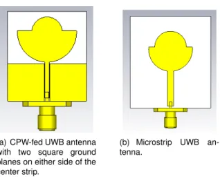
In [60] and [12], a comparison regarding the performance of microstrip and CPW solutions is evaluated, and other variants of the latter are suggested. The third solution is an alternative to the latter, named by GCPW a) CPW-fed UWB antenna with two square ground planes on either side of the center band. The GCPW solution will be elaborated further, but it was studied as it consists of a mixture of CPW and microstrip solutions [1].
The introduction of slots was beyond the intended goal, so the size and reformation were investigated. One can observe a slight improvement in the magnitude of the reflection coefficient when the shape of the ground planes goes from the square format (Figure 3.24(a)), beyond the elliptical one (Figure 3.24(b)), to the scenario in which each ground plane has a configuration of a quarter of a circumference (Figure 3.24(c)). Therefore, the final design of the optimized UWB antenna is presented in Figure 3.24(c), and Table 3.3 which displays the values, in mm, of the dimensions of Figure 3.25.
Prototype test of the designed antennas
Fabrication and measurement setup
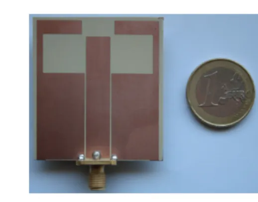
The next procedure is called 'chemical etching' and consists of dissolving (in a corrosive manner) the parts that do not belong to the antenna arrangement. The next step of this manufacturing method is to place an image of the metal pattern on each side of the patch. The unexposed areas of the photoresist are washed away and the remaining areas go under the etching portion of the chemical etching process.
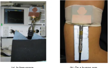
The patch finally undergoes a proper alkaline solution to wash away the rest of the photoresist and the cleaning process from the beginning is performed again. An RF cable is connected directly to the feed line of the antenna, via the connector, as shown in Figure 4.1(b). The following sections are devoted to the evaluation of the behavior of both antennas, in free space and in the environment of the human body.
Dual-band Antenna
- Free-space scenario
- Behaviour in the vicinity of the human body
The conductivity of human tissue is σ (given in S.m−1); ρ is the density of the tissue sample (in. Before proceeding with the SAR calculation using the CST software, Table 4.2 summarizes Table 4 from [20] for the current dual-band antenna example. Place this coverage calculation in the CSTT MM icwaveStudio environment, with the antenna positioned 3 and 7mm away from a simple human body model.
According to the parameters of the tissue of the models (see Table 4.6), the total mass defined for the flat model is equal to 820 g. Figures 4.4(a) and 4.4(b) show the simulation scenario using respectively the flat and elliptical simplified models of a human limb. Also, since it can be observed from Figures 4.4 and 4.8 that although they. a) Antenna measured on the human user's arm.
UWB antenna
- Free-space behaviour
- Behaviour in the human arm proximity
The antenna is thus prepared to be used near the human body without restrictions. Noteworthy is the strong influence of the fabrics of the simple models on the performance of the antenna. The antenna is placed on the human user's arm and secured with a latex strap (see Figure 4.13(a)).
To keep the antenna at a certain distance from the human arm, a strip of polyethylene is again used (Figure 4.13(b)). By comparing with Figure 4.12 one can see that the elliptical. a) Antenna measured on the arm of the human user. Compared to the microstrip antenna designed previously in this chapter, one can increase the sensitivity of the.
Conclusions and Future Work
Conclusions
However, two factors concerned the author: the lack of copper shielding at the back of the CPW-fed antenna and features favored by the microstrip solution but not by the coplanar. A calibrated VNA from Agilent Technologies is used for the measurements and an RF cable is connected to the power line of the antennas. In terms of simulation, two simple four-layer models of the human body are used, one flat and one elliptical.
In terms of measurements with the antenna on the human user, the results again show a serious impact on the operating band of the UWB antenna. However, the higher frequencies are not affected as much, which points out one of the properties of the CPW solution. The sensitivity of the CPW solution to the same influence is seen, and so a microstrip solution may be in order.
Future Work
Finally, the author believes that the present dissertation has fulfilled all the proposed goals and has made a small contribution to the world of wireless area networks. For more ambitious work, narrowband dual-band antennas are interesting for Internet of Things (IoT) applications. The frequency dual property of the designed microstrip patch antenna presents an opportunity to study the dual capacity of the system with frequency reuse.
Other substrate materials can be used to improve return loss and further reduce the physical dimensions of the antenna. Nevertheless, the optimization of the UWB antenna is in place, and the CPW solution should be reviewed as it allows easy integration with active devices. An example of this is connecting an antenna to a device that can reconfigure its output parameters (radiation pattern, directivity, and more) according to a changing environment, improving the UWB antenna's performance.
Appendix A
SMA Connector
Appendix B
AutoCAD Masks
Bibliography
The effect of dielectric permittivity on the radiation characteristics of a coaxially fed rectangular patch antenna: Design &. Effect of ground plane and patch slots on microstrip antenna performance. International Journal of Recent Trends in Engineering. On the use of u-slots in the design of dual- and triple-band patch antennas.
Artificial human phantoms: human proxy in testing microwave devices that electromagnetically interact with the human body. InProceedings of the 6th International Conference on Body Area Networks, BodyNets '11, pages 54–59, ICST, Brussels, Belgium, Belgium, 2011. Impact of body and clothing on a wearable textile dual-band antenna on digital television and wireless communication bands.
![Figure 1.2: Frequency bands for WBAN in different countries, retrieved from [33].](https://thumb-eu.123doks.com/thumbv2/123dok_br/19768800.0/23.892.140.746.199.452/figure-frequency-bands-wban-different-countries-retrieved-33.webp)