U . S . B L I N D S T I T C H M A C H I N E C O R R
Express Street & Skyline Drive, Plainview, L. 1., New York 11803 Telephone: 5 1 6 - 4 3 3 - 4 3 5 0
C a b l e : "BUNSTIT PLAINVIEW NEWYORK"
PARTS CATALOG
and MAINTENPE
MANUAL for MACHINE MODEL
SiFrom the library of: Superior Sewing Machine & Supply LLC
HOW TO ORDER PARTS
PURCHASE ORDER
QUANTITY DESCRIPTION PRICE
1 12
FOR U.S. MODEL 718-1 - SERIAL NO. xxxxx
Part No. 2100 Feed Dog P a r t No. 1238 Needle Guide
If parts are being ordered for several machines the Purchase Order should be prepared in a similar
fashion to the following example:
1 12
FOR U.S. MODEL 718-1 - SERIAL NO. xxxxx Part No. 2100 Feed Dog
P a r t No. 1238 Needle Guide
FOR U.S. MODEL 718-1 - SERIAL NO. yyyyy
P a r t No. 1046 Handwheel
Part No. 1119 Screws - Feed Dog Attaching FOR U.S. MODEL 718-5 - SERIAL NO. z z z z z
Part No. 2112 Feed Dog
AMOUNT
Be SURE to Specify AAodel and Serial
number of machine when ordering parts!
.0 n D n 0 n
0 D
n
0
n
n
n
n
I I I - MAINTENANCE INSTRUCTIONS
INTRODUCTION
A. Replacing the Looper
B. Replacing the Needle Guide C. Replacing the Shoe
D. Replacing the Feeder
MAINTENANCE INSTRUCTIONS
INTRODUCTION
All U.S. BLIND STITCH machines are designed for long life and trouble-free performance. V?hen installed and l\ibricated in
accordance with the INSTALLATION AND OPERATING INSTRUCTIONS, only the minimum maintenance normally associated with industrial sewing machines will be required. These maintenance requirements will generally be confined to the four locations described below, at which wear may be expected after extended use. When such wear does occur, the worn part may be readily replaced by following the
appropriate instructions. For ease of installation, and to insure satisfactory service, i t is essential that only genuine U.S. BLIND STITCH parts and needles are used. They are the only parts designed specifically for the machine, with the built-in long life and ex cellent wearing characteristics typical of the U.S. BLIND STITCH
machine.
A. REPLACING THE LOOPER
1. Should i t become necessary to replace the looper
(item "B" in Figure 6), loosen the looper clamp screw (item "A" in Figure 6) and remove the old looper.
Because of the precise f i t of the looper in the looper rod i t may be necessary to exert a moderate amount of force to pull the looper out. Insert the new looper into the end of the rod as far as i t will go before bottoming on the looper shoulder.
2. Any time a looper is moved or changed, recheck the looper timing and reset i f necessary. Proper looper timing is absolutely essential for correct stitch formation. As described in detail below, a properly timed looper will pass over the needle in the correct position to pick up the loop, and also clear the chain-off pin, feeder,
looper slot, and needle. The f i r s t check point for timing the looper is at the position where the looper picks the thread loop off the needle during the needle return stroke.
Referring to Figure 7, (Point "C"), the long prong of the looper should pass over and just clear the scarf of the needle, approximately 3/32" (2.4mm) behind the end of the needle eye. At the same time, the short prong of the looper should pass over the needle with about 1/64"
(.406mm) clearance, and must be so set that i t also clears the chain-off pin (item "D" in Figure 7).
Q
FIGURE 6
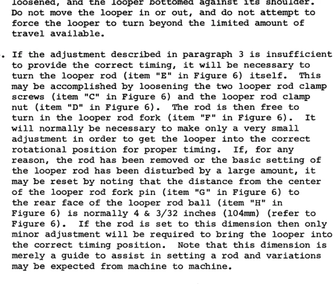
3. To adjust the looper so that the timing checks out as noted in paragraph 2, i t may be rotated within its clamp by a limited amount. This adjustment should be made
with the looper clcunp screw (item "A" in Figure 6)
loosened, and the looper bottomed against i t s shoulder.
Do not move the looper in or out, and do not attempt to force the looper to turn beyond the limited amount of
t r a v e l a v a i l a b l e .
4. If the adjustment described in paragraph 3 is insufficient to provide the correct timing, i t will be necessary to turn the looper rod (item "E" in Figure 6) itself. This may be accomplished by loosening the two looper rod clamp screws (item "C" in Figure 6) and the looper rod clamp nut (item "D" in Figure 6). The rod is then free to turn in the looper rod fork (item "F" in Figure 6). I t will normally be necessary to make only a very small
adjustment in order to get the looper into the correct rotational position for proper timing. If, for any
reason, the rod has been removed or the basic setting of the looper rod has been disturbed by a large amount, i t may be reset by noting that the distance from the center of the looper rod fork pin (item "G" in Figure 6) to the rear face of the looper rod ball (item "H" in
Figure 6) is normally 4 & 3/32 inches (104mm) (refer to Figure 6). If the rod is set to this dimension then only minor adjustment will be required to bring the looper into the correct timing position. Note that this dimension is merely a guide to assist in setting a rod and variations may be expected from machine to machine.
5. If, after completing the above adjustments, i t is found that the looper is either too low or too high, i t will be necessary to adjust the eccentric block. First loosen the two set screws (item "A" in Figure 7). Place a wide
blade screwdriver i n the s l o t of the e c c e n t r i c block
(item "B" in Figure 7) and, using a slight turning motion,
raise or lower the looper as required. Once the proper height is established, check to see whether the looper must be moved to the left or to the right prior to re- tightening the eccentric block set screws. I f such a movement is required, i t may be obtained by lightlytapping the eccentric block in the correct direction with t h e handle o f a screwdriver.
• ^ t a
FIGURE 7
6. Once the looper is timed with respect to the needle as outlined in paragraphs 2 thru 5 above, slowly turn the handwheel in a direction away from the operator, until
the looper approaches the edge of the looper slot (Point "C" in Figure 8) in the presserfoot. At this point make sure the small prong of the looper clears this edge. If i t does not clear, adjust the eccentric block as outlined in paragraph 5 until the interference
i s e l i m i n a t e d .
7. Continue turning the handwheel away from the operator until the point of the needle starts to enter the area in between the looper prongs. (Refer to Point "D" in Figure 8). If the needle strikes the crotch of the looper, the looper has generally been set too far for ward. Check to see i f the looper has been inserted into the clamp as far as i t will go. I t should be inserted until the shoulder on the looper is stopped on the clamp.
If this check is satisfactory, recheck the distance from the center of the looper rod fork pin to the rear face of the looper rod ball. Refer to paragraph 4 and reset i f necessary. If neither of the above two measures corrects the problem, i t is possible that the needle lever may be set too low and requires adjustment.
8 . Once c l e a r a n c e i s e s t a b l i s h e d between t h e needle and t h e
looper crotch, continue turning the handwheel away from the operator until the needle passes between the looper prongs, clearing both the long and the short prong. I f difficulty is experienced at this point, i t may be
necessary to modify some of the previous adjustments to the eccentric block or the looper rod length. I f this is done, recheck the previous points to insure that a posi tion is established which will satisfy a l l of the clear
ance c o n d i t i o n s .
9. After all the necessary adjustments have been made, tighten a l l set screws and the lock nut and recheck a l l the adjustment points. Referring to Figure 9 the looper should now clear the chain-off pin ("D"), feeder ("E"), looper slot ("F"), needle, and pass over the needle in the correct position to pick up the loop.
B. REPLACING THE NEEDLE GUIDE
1. After considerable service, i t may be expected that the wearing action of the needle will cause a sharp edged
groove to form on the needle guide (item "G" in Figure 9).
FIGURE 8
This condition can cause thread breakage and uneven penetration. When this happens the guide should be replaced. The needle guide was specifically designed as a readily replaceable wear plate to prevent damage to the presserfoot from the action of the needle.
2o Loosen the needle guide attaching screw (item "A" in Figure 9) and remove the worn needle guide. Clean
out any l i n t or dirt that may have accumulated under the old guide and insert the new guide. Insure that the new guide is seated flush with the top and side of the presserfoot and then retighten the attaching screw.
Slowly turn the handwheel in the direction away from the operator and check to insure that the new guide fits properly under the needle and that no interference has been introduced between the guide and the looper.
C. REPLACING THE SHOE
1. The shoe, (item "E" in Figure 8), also known as a cloth retainer, normally will not require replacement.
However, in the event of wear due to the particular fabrics being used, or i f the shoe or spring suffers any damage, they may be readily replaced.
2. The f i r s t step is to remove the complete front guide assembly by unscrewing the front guide holder attaching screw (item "A" in Figure 8). Next loosen the shoe pin lock screw (item "B" in Figure 8) and slide out the shoe pin (item "F"), shoe and retaining spring (item "G").
Before removing these components i t is advisable to note the manner in which the spring is asseiribled so that i t may be reinstalled in the same way.
3. When replacing an old shoe, make sure that the replacement shoe properly fits the pin without binding and without excessive looseness. In the event that the pin has worn and does not f i t the new shoe properly, i t should be replaced at the same time as the shoe. After replacing the shoe, shoe pin and retaining spring retighten the shoe pin lock screw and check to insure that the center of the
shoe is lined up with the center of the rib. Also insure that the shoe clears both sides of the opening in the presserfoot.
ssammmm^ KUfiliiSHiK
D. REPLACING THE FEEDER
1. In the event that the machine develops difficulty by failing to properly feed the work, a worn feeder is frequently found to be the cause. After considerable service, especially with certain hard fabrics, the feeder teeth have a tendency to become dull, and the feeder should be replaced. In order to remove the old feeder, remove the front feeder attaching screw (item "B"
in Figure 9) and loosen the rear feeder attaching screw (item "C" in Figure 9). The old feeder may then be slid out of place. Insert the new feeder under the rear screw and replace the front screw.
2. Before tightening the attaching screws check to see that the feeder is set to the proper depth. Referring to Figure 10 this should be approximately 1/32" (.795mm) below and parallel to the bottom of the presserfoot for a l l light and medium weight fabrics. For heavy fabrics, the setting should be approximately 1/16" (1.59mm) below and parallel to the bottom of the presserfoot. These dimensions are intended as guides and may be modified as required by the specific fabrics. Once the proper depth is established, rotate the handwheel slowly in a direction away from the operator and check to insure
that the feeder clears the looper (see Figure 9, Point "H")
and a l s o c l e a r s b o t h s i d e s o f t h e feeder s l o t i n t h e
presserfoot. Firmly tighten feeder attaching screws (Figure 9, Items "B" & "C") before resuming sewing.
FIGURE 10
NOTE
The following parts catalogue consists of a complete basic catalogue plus the pink parts l i s t sheet which
immediately follows this note. When looking for a
particular part, first consult the pink sheet. If the
part does not appear on this sheet alongside theappropriate section, then turn to the corresponding
section in the main catalogue and refer to the partnumber l i s t e d t h e r e .
PARTS LIST FOR U.S. BLIND STITCH MACHINE MODEL
99-PB
This parts list is the same as the parts list for the basic Model 99-CS
with the following deletions and additions:
GROUP
MAIN FRAME
MAIN SHAFT
NEEDLE DRIVE
FEED DRIVE
LOOPER DRIVE
FEED FRAME I
^ FEED FRAME II
REGULATING
FRONT PLATE
PRESSERFOOT
USE PART NUMBER
None
5041
None
None
None
6038
None
None
2507 1236 1304 2603
INSTEAD OF
PART NUMBER
5004
6007
2501 1235 1239 2600
DESCRIPTION
Needle Connection Assembly
Rib Shaft Assembly
No Front P l a t e
Shoe - Presserfoot
Pivot Pin - Presserfoot Shoe
Spring - Presserfoot Shoe
Front Guide
Pa«e 1 of 1 Page
Date: December 1, 1962
.1...
;-r-.
PARTS CATALOGUE
INTRODUCTION
A. Main Frame Group B. Main Shaft Group C. Needle Drive Group D. Feed Drive Group E. Looper Drive Group F. Feed Frame Group I G. Feed Frame Group II H. Regulating Group
I. Front Plate Group J. Presserfoot Group
INTRODUCTION
This Parts Catalogue has been designed as an integral part of the U.S. BLIND STITCH MACHINE CORPORATION'S well known Spare Parts Supply system. Parts and needle orders are normally filled and shipped on the day they are received. A completely stocked Spare Parts Department is maintained to insure the immediate availability of parts and needles for a l l U.S. BLIND STITCH machines. In order to facilitate the ordering of parts and insure the accuracy of the order, this catalogue has been arranged in an extremely simple and straight-forward fashion.
A unique feature of this new U.S. BLIND STITCH catalogue is the availability of a specific catalogue for each of the many
different U.S. BLIND STITCH models. This automatically eliminates the complicated searching cimong long lists of parts. I t thus
greatly reduces the time required to select the needed part number while at the same time increasing the accuracy of the selection. In practically all cases each part is represented by one and only one part number, which eliminates the necessity for selecting a particular variation. In the few instances where an option is offered on a particular model, the choice is clearly spelled out.
With this type of arrangement the procedure for ordering spare parts becomes extremely simple, as outlined below: Assume that i t
is necessary to obtain a replacement presserfoot shoe for a U.S.
machine.
1. First, observe the model designation stamped on the nameplate located on top of the main frame (Refer to Figure 11). Make
a n o t e o f t h e number.
2. Observe the particular machine serial number stamped on the bottom rear of the base casting (Refer to Figure 11). Note
t h i s number.
3. Select the catalogue for the model number noted in item (1).
This model is clearly printed on the cover of the catalogue.
4. Note that the Parts Catalogue is divided into ten sections, each covering a different functional grouping of machine parts. The part in question here, namely the presserfoot shoe, obviously falls in Section J which covers the Presser foot Group. Turn to this page and, referring to the
i l l u s t r a t i o n , note the reference number attached to the presserfoot shoe.
INTRODUCTION (CONTINUED)
5, The page facing the illustration contains a listing of each
part in the illustration together with the reference number and the part number. Using the reference number noted in item 4, find the part listing and part nuirber. THIS IS THE PART NUMBER TO ORDER. (PARTS CANNOT BE ORDERED BY REFERENCE NUMBER.)6. In order to completely eliminate any possibility of error, with each part ordered i t is essential that mention is made of model designation (item 1 above), serial number (item 2 above), and part nuirber (item 5 above).
After a very brief period of familiarization with the Parts
Catalogue i t will be found that ordering spare parts is a simple and quick procedure. Specifying model nuirber, serial number and part number provides a fool-proof combination of information which will insure that the correct part is received in the shortest
possible time. Refer to Figure 12 for an illustration of a properly prepared purchase order.
In using the Parts Catalogue i t may be noted that certain part numbers carry the prefix T. This designates an assembly which is precision matched at the factory for proper operation and long
l i f e . For this reason, the various components will not be sold separately insofar as we cannot insure customer satisfaction
unless they are factory fitted. If a part of any of these assemblies bearing the prefix T requires replacement, i t will be necessary to replace the entire assembly. The few assemblies involved are shown in outline drawings on the illustration sheet, and play a critical role in the proper functioning of the U.S. machine. In those cases where the assemblies involved also include non-matched components
such as screws, these, of course, will be provided as separate spare parts. Such components are shown on the illustration sheet and listed on the parts sheet immediately below the affected
assembly.
Certain assemblies which do not require critical matching are available either as complete assemblies or detail components to suit the convenience of the customer. The complete assembly carries a separate reference number and part number. The detail components also have individual reference numbers and part numbers and are listed immediately below the assembly in the parts l i s t .
Machine Model No.
r
000000 Machine Serial No.
FIGURE 11
n
PURCHASE ORDER
QUANTITY DESCRIPTION PRICE AMOUNT
1 12
FOR U.S. MODEL 718-1 - SERIAL NO. x x x x x
Part No. 2100 Feed Dog
P a r t No. 1238 Needle Guide
If parts are being ordered for several machines the Purchase Order should be prepared in a similar
fashion to the following example:
1 12
FOR U.S. MODEL 718-1 - SERIAL NO. xxxxx
Part No. 2100 Feed Dog
P a r t No. 1238 Needle Guide
FOR U.S. MODEL 718-1 - SERIAL NO. yyyyy
Part No. 1046 Handwheel
Part No. 1119 Screws - Feed Dog Attaching FOR U.S. MODEL 718-5 - SERIAL NO.
Part No. 2112 Feed Dog
z z z z z
FIGURE 12
\
From the library of: Superior Sewing Machine & Supply LLC
REFERENCE NO.
MAIN FRAME GROUP
DESCRIPTION
PART QTY.THIS NO. APPLICATION
1 S i d e Cover 5001 1
2 O i l Tube 1005 1
3 O i l Wick 1006 2
4 B e l t Guard 1068 1
5 Screw - B e l t Guard S e t 1069 1
6 Cover P l a t e 1081 1
7 Screw - Cover Plate Attaching 1096 1
8 Screw - Side Cover Attaching 5019 1
9 F r o n t Thread Guide 1080 1
10 Screw - Front Thread Guide Attaching 1070 1
11 Screw - L i f t Arm L i m i t 1332 1
12 Nut - L i f t Arm L i m i t Screw-Lock 1
13 Thread Tension Regulating Assembly -
^0Q2\
114 Tension Post ^
Tension Discs
{ 1082 1
115
1 1083 \
216 Thread Guide •
Spring ^
Cover
Nut /
\ 1084 \
117
1 1085 \
118
\ 1009
119
1 /
120 R a t c h e t
1 1011 J
121 Screw - Feed Frame S h a f t - S e t 1093 2
22 Screw - E c c e n t r i c Block - S e t 1289 2
23 E c c e n t r i c P i n 1240 1
24 Screw - E c c e n t r i c P i n S e t 1094 1
Wfiiit,
main shaft group REFERENCE
ran DESCRIPTION
PART Nb.
1 Main Shaft 1044
2 Handwheel 1043
3
Screw - HcUidwheel Set (Cone Point)
1121'4
Screw - HandWheel Set (Cup Point)
10695 Screw - Feed Eccentric Set 1331®
6 Rib Connection Assembly T5003 -
7 Screw ~ Rib Lever Eccentric Lock 1120
8 Screw - Rib Connecting Lever Clamp 1071
9 Needle Connection Assenibly T5004
10 Screw - Needle Connection 1072
11 Eccentric Ball Guard 1134
12 Screw - Eccentric Ball Guard Attaching 1132
13 Oil Wick 1419
QTY. THIS
APPLICATION
^^^S«SSSS§SS
NEEDLE DRIVE GROUP
REFERENCE
NOc DESCRIPTION
1 2 3 4 5 6 7 8 9 10 11
Needle Screw - C o l l a r Screw - Needle
Needle Screw • Screw • Needle
S h a f t
Needle Shaft Claii^
- Needle Shaft
• Needle Shaft Collar Set
Lever Assembly
Needle Lever
Pin - Needle Clamp Locating Clamp
• Needle Clamp Attaching - Needle Lever Clcimp
*Specify Size. Genuine U.S. Needles are
available in the following sizessLONG POINT 0
10 15 20 25 30 35 40 400
SHORT POINT 1
2
2h
3
33s
4
43s
PART QTY.THIS NO. APPLICATION
1095 1118 1135 1094 5021 1136 1243 1137 1076 1097 1017*
n
n
n
n
%
(D-
Needle Drive Group
C1From the library of: Superior Sewing Machine & Supply LLC
FEED DRIVE GROUP
REFERENCE
NO. DESCRIPTION
PART QTY. THIS NO. APPLICATION
Stitch Regulating Collar
Screw - Stitch Regulating Collar-Clamp
Feed Lever
Rocker Pin Assembly Collar - Rocker Pin
Screw - Rocker Pin Collar-Clamp Screw - Feed Dog - Attaching Feed Dog
10919 1072 1138®
5016 1145 • 1076 1119 2100*
*Specify this number for regular coarse tooth
feed dogs (12 rows of teeth per inch). For the fine tooth feed dog (20 rows of teeth per inch)
specify feed dog part No. 2101.i I
n
n
i r
Feed Drive Group
D1
From the library of: Superior Sewing Machine & Supply LLC
LOOPER DRIVE GROUP
REFERENCE
NO. DESCRIPTION
1 2 3 4 5 6 7 8 9 10 11 12 13
EA
Looper Rod Fork & Sleeve Assembly Screw-Looper Rod Fork-Clamp Screw-Looper Rod Fork Pin-Set Stud - Looper Rod Sleeve
Nut - Looper Rod Sleeve Stud Looper Rod & Carrier Assembly
Screw - Looper Rod Carrier-Clamp Screw - Looper Rod Ball-Set
Stud - Looper Rod Carrier
E c c e n t r i c Block
Nut - Looper Rod-Lock Screw - Looper Clamp Looper
PART NO.
T5006 1077 1094 1123 1146 T5008 1072 1098 1149 1150 1151 1156 2200
QTY. THIS APPLICATION
! I
i I
I \
1 1 I I 1 1 1 1 1 I 1 I 1 1 1 I I
Looper Drive Group
El
From the library of: Superior Sewing Machine & Supply LLC
PEED FRAME GROUP - I
REFERENCE FART QTY.THIS
NO. DESCRIPTION NO. AFFLICATIOK
1 Feed Frame and Bushing Assembly 5042 1
2 Rib Shaft Bushing - Right 1088 1
3 Rib Shaft Bushing - Left 1087 1
4 Rib Shaft Assexobly 6007 1
5 Rib Shaft Collar - Left 1161 1
6 Rib Shaft Collar - Right 1162 1
7 Screw - Rib Shaft Collar-Clamp 1076 o
8 Crank - Rib Shaft 1163* 1
9 Stud - Rib Shaft Crank 1164* 1
10 Screw -'Rib Shaft Crank - Clamp 1117 1
11 S t u d - Flatten Bracket Pivot 1166 1
12 Screw - Flatten Bracket Pivot Stud-Set 1069 1
13 F l a t t e n Bracket - Left 2451 1
14 Flatten Bracket - Right 2450 1
15 F l a t t e n - Left 2400 1
16 Flatten - Right 2401 1
17 Spacer - Flatten Bracket 1021 As Required
18 Spring - Flatten Bracket 1171 . 2
19 Screw - Flatten Bracket - Limit 1114 2
20 Nut - Flatten Bracket Limit Screw-Lock 1168 2 21 Screw - Flatten to Bracket - Attaching 1244 2
22 Nut - Flatten to Bracket Attaching screw 1167 2
23 Screw - Peed Frame - Limit 1104 1
.24 Nut - Peed Frame Limit Screw-Lock 1146 1
25 Window P l a t e 1205 1
26 Screw - Window Plate Attaching 1030 1
27 Cylinder 1211 1
28 Screw - Cylinder Attaching 1101 3
FXX
*These parts are available separately.
However, i t is recoiranended that, i f
either requires replacement, both should
be replaced with a pair of factoryfitted parts.
I
FEED FRAME GROUP - I I
REFERENCE PART
NO. DESCRIPTION NO.
1
Spring Link Assenibly
50202
Nut - Spring Link Assembly-Retaining
11463
. Screw - Spring Link-Locating
11594 Link Screw - Main Spring 1177
5 Nut - Main Spring Adjusting 1184
6 Main Spring 1190
7 Shaft - Feed Frame Rocker 1066
8 Lift Arm Assembly 5060
9 L i f t Arm 1335
10 Pin-Lifting 1406
11 Hook - Knee Lifter 1334
12 Screw - Lift Arm Clamp 1120
13 Screw - L i f t Arm Limit 1035
14 Nut - Lift Arm Limit Screw - Lock 1008
15 Knee Lifter Rod 1060
16 Collar - Knee Lifter Rod 1059
17 Screw - Knee Lifter Rod Collar-Set 1036 18
Spring - Knee Lifter Rod-Return
106119 Knee Pedal 1208
20 Screw - Knee Pedal-Lock 1037
61
^ W
Ae\ ®\kacV<^
vA»^® vA^;^
QTY.THIS APPLICATION
n
NOTICE
This catalogue lists the latest "hook-type" knee lifter configuration, For machines which incorporate the "toggle bolt-type" knee lifter, please observe the following differences. (The toggle bolt-type
lifter may be recognized by the bolt which extends through a hole
in the top of the feed frame.)GROUP
FEED FRAME I I
USE PART NUMBER
5014 1210
1204 1031 1206 1032
1207 1033
INSTEAD OF
PART NUMBER
5060 1335 1406
1334
DESCRIPTION
Lift arm Assembly
L i f t Arm Link Pin
L i f t Arm Clevis P i n - L i f t Arm C l e v i s
Toggle Bolt
Pin-Toggle Bolt Pivot
Hook-Feed Frame L i f t e r Swivel Washer
Nut-Toggle Bolt Lock
REFERENCE NO^
REGUIATING GROUP
DESCRIPTION
1 Regulating Pork
2 Pin - Regulating Pork-Pivot 3 Push Rod Assembly (3/8") 4 Push Rod (3/8")
5 Retaining Pin
6 Spring - Push Rod (3/8") 7 Regulating Dial Assembly 8 Regulating Dial Shoe 9 Regulating Dial Screw
10 Pace Plate & Guide Pin Assembly
11 Dial and Ratchet Assembly12 Screw - Dial & Ratchet Assenibly-Lock 13 Screw - Regulating Dial Assembly Attaching
HB
PART QTY, THIS NO. APPLICATION 1186
1025 5012 1195 1023 1024 5018 1223 1222 5010 5039 1039 1109
n
n
m
r.EFERENCE NO.
FRONT PIATE GROUP
DESCRIPTION
PART QT5f. THIS NO. APPLICATION
1 Swing Plate 1200
2 Pivot Pin - Swing Plate 1225 '
3 Retaining Ring - Swing Plate Pivot Pin 1048^^
4 Collar-Swing Plate Pivot Pin 1226 ^
5 Screw-Swing Plate Pivot Pin Collar-Set 1049
5 Bracket - Swing Plate-rSupport 1228
7 Screw-Swing Plate Support Bracket-Attaching 1103
3 V7asher (Flat)-Swing Plate Supp't. Brkt. Screw 1230
9 Washer (Lock)-Swing Plate Supp*t. Brkt. Screw 122910 Stop Pin Assembly 5015«
11 stop Plate 1227
12 Screw-Stop Plate Attaching 1052
13 Washer - Stop Plate Attaching Screw 1053
14 Screw - Stop Pin-Lock 1051
15 Screw - Swing Plate Pivot Pin-Lock 1051
IG
4 I * 1 1 1 j 1 1 I n
®® ©
Front Piate Group
I I > j : j
•
•j -~.
.Q
PRESSERFOOT GROUP REFERENCE
NO. DESCRIPTION
1 2 3 4 5 6 7 8 9 10 11 11 13 14 15 16 17 18
JOO
Presserfoot Assembly
P r e s s e r f o o t
Bridge
Chain-Off Pin Shoe Post Shoe - Presserfoot
Pivot Pin - Presserfoot Shoe
Screw - Presserfoot Shoe Pivot Pin-Set Spring - Presserfoot Shoe
Front Guide
Holder - Front Guide
Screw - Front Guide Holder-Attaching
Nut - Front Guide to Front Guide Holder-Att Needle Guide
Screw - Needle Guide-Attaching Screw - Presserfoot Clamp
Washer - Presserfoot Clamp Screw Screw - Presserfoot Bridge
V5. 0
PART NO.
QTY. THIS APPLICATION
6100 2300 1241 1315 1233 2501 1235' 1106 1239 2600 5028 1099 • 1283
1238 ^
1122-' llOS*^
1054 1107
1 1 1 1 1 1 1 1 1 1 1 1 1 1 1 1 1 2
From the library of: Superior Sewing Machine & Supply LLC
f 1 1 I 1 1 1 1 1 I 1 1 1 I I I I I i
K a«i
I'
Presser Foot Group
^ no^
KA
ACCESSORY GROUP
PART QTY.THIS
DESCRIPTION NO. APPLICATION
Bolt-Machine Mounting 4513 2
Wing Nut-Machine Mounting Bolt Attaching 4541 2 Washer-Machine Mounting Bolt (1-3/8" O.D.) 4505 2 Washer-Machine Mounting Bolt (1" O.D.) 4546 2
Felt Pad-Machine Mounting 4543 1
Rubber Pad-Knee Lifter 4544 1
Cotton Stand-Base & Spool Post Assembly 9527 1
Thread Post 4545 1
Wood Screw-Cotton Stand Attaching 4533 2
Oil Can 9528 1
Screw Driver 9529 1
r'jV ,*.•
c
i t
n'
n
n
n n n
n
n
n
r
AMachine is Only as Good as its NEEDLE!
Don't Take Chances—Avoid Trouble
Top-quality sewing demands top-quality machines equipped with top-quality needles to achieve perfect results.
Peak efficiency in today's high-speed sewing of synthetic and wash and wear fabrics is accomplished only with needles of superior quality and perfoimance.
Imitations or substitutes are a costly compromise. Pennies saved on inferior needles only prove to be expensive dollars in the long run.
U. S. Blind Stitch needles are made in the United States to U. S. specifications of the finest materials and workmanship available.
The quality of U. S. Needles is, in fact, a matter of world-wide recognition and cannot be duplicated. The confidence of our customers in U. S. needles is the knowledge that quality is and always has been foremost in our products.
For durability and freedom from breakage, U. S. Needles are unequalled. Their uniform construction, carefully controlled finish
and curvature assure efficient, economical stitching.
BE SURE TO USE ONLY GENUINE U. S. NEEDLES
fyt fhk
on all parts
The same precision construction and working perfection exists in all U. S. Machine Parts.
GENUINE U.S. NEEDLES
U.S. BUNDSTITCH MACHINE CORP.
231 W. 29fli St NEW YORK 1, N.Y.
MADE IN U.SA
BE SURE TO GET U. S. — ACCEPT NO SUBSTITUTE
Printed in