The paradigms of IoT and cloud-assisted computing can help address these issues. On the one hand, Utility Cloud Computing provides the illusion of infinite computing resources available to public users on demand [5].
Application Domains
Smart Places Challenges
By leveraging the smart place infrastructure to the cloud, the cost of its infrastructure can be significantly reduced. However, the performance of the smart site will be satisfactory when its infrastructure is leveraged to the cloud.
Objectives
Example Domain
However, in a cloud-based deployment, part of the system's infrastructure is moved to the cloud - for example, the middleware layer, which is responsible for processing the information and making decisions based on the results. Since the cloud platform offers flexibility to deploy applications, we propose a solution that automates the deployment of RFID application middleware in the cloud regarding the chosen approach: cloud or fog.
Dissertation Outline
Smart Place Computing
- Containers
The cloud is used at the IaaS level, which allows measuring the utility of services provided by interconnected objects. CloudThings [16] is an architecture that uses cloud platform layers to integrate the Internet of Things and Cloud Computing. The proposed architecture aims to enable vertical virtual service delivery, therefore it has a multi-tenant nature which is designed to help isolate different solution environments.
While significant progress has been made in improving the deployment of IoT solutions, most of the work is still in a conceptual stage.
Data Storage
- Key-value Stores
- Relational Database Clusters
- RFID Middleware Platforms
Although most of the works are still in development, it is possible to highlight some solutions that are in a more mature state. Choosing the best solution will depend on the application domain and its requirements. In order to improve the performance of the EPCGlobal compliant middleware platforms, the new infrastructure adopts a decentralized architecture where the EPCIS is deployed in the cloud and is connected to a NoSQL database instead of MySQL.
A prototype of the proposed infrastructure is currently being developed using OpenNebula, pthreads and Service Oriented Architecture (SOA).
Configuration Management Tools
- Chef
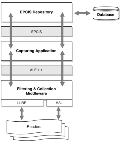
The Fosstrak platform has been evaluated and the results show that Fosstrak is not the best option when running the modules responsible for collecting the data (ALE) from RFID readers and storing the event data (EPCIS) in the same machine. The ALE module uses a multi-threading architecture to support high parallel demand for RFID readers.
Fog computing for low latency responses
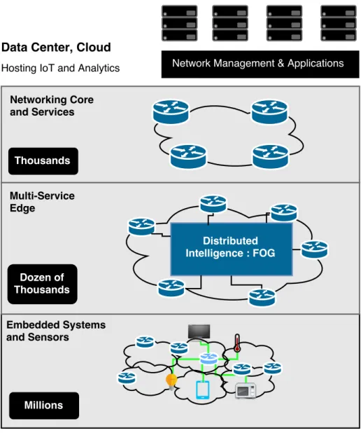
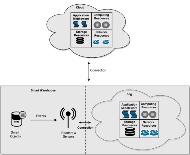
Core Networking and Servicestier is responsible for providing network services used to exchange data between subnetworks. It is important to show that the higher the level, the wider the geographical coverage and the larger the time scale [29]. The global coverage is given by theCloud layer, which serves as a central repository for the persistent data and which is used to perform business analytics.
Internet of Things frameworks
Internet of Things stack example: EPC Framework
- GS1 EPCglobal Architecture
- Fosstrak Platform
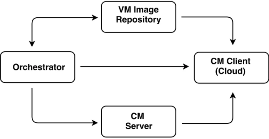
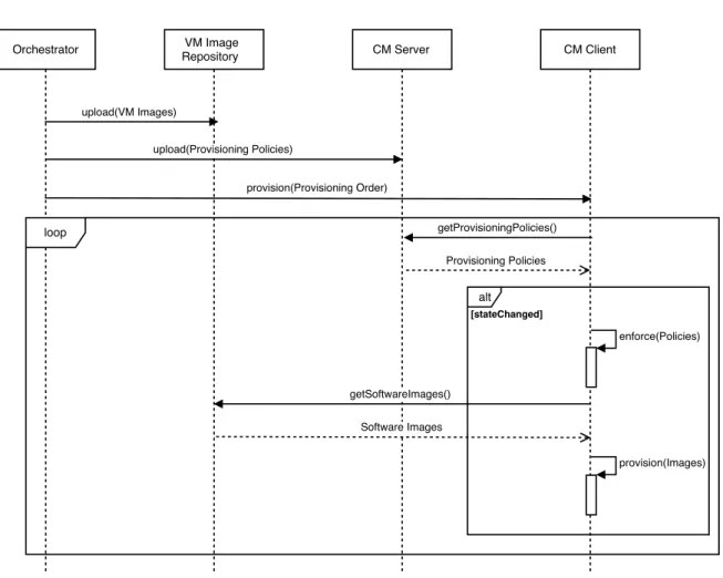
In terms of implementation, the Capturing application is built on top of the Drools17 engine, where rules can be specified in terms of: "when" something happens, "then" do "this". In Section 3.2, we describe the alternative architectures for the smart storage with respect to the chosen implementation approach. When the provisioning request is made - through a configuration management interface provided by Orchestrator - the configuration management client (CM Client) in the cloud server pulls the policies from the configuration management server (CM Server), a centralized server responsible for maintaining a consistent state of the provisioned nodes in the cloud.
To enforce the policy, the CM Client retrieves the software images from a central repository and then performs provisioning and configuration of the software.
Implementation Details
- Provisioning Recipes
- Provisioning Roles
- Provisioning Mechanism
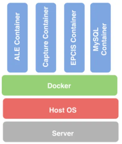
- Docker Containers
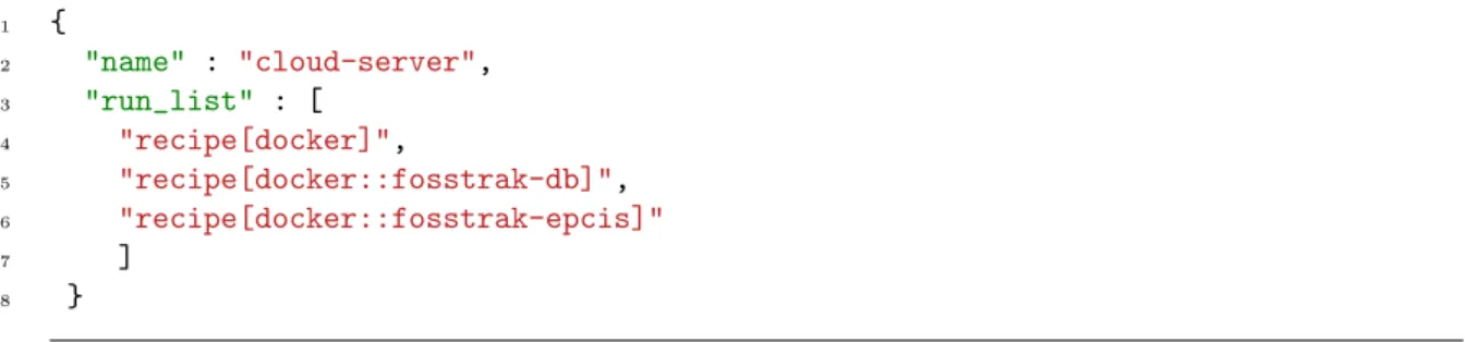
We have therefore defined a single role to describe the responsibilities of the node provisioned in the cloud. Thefosstrak role describes that the nodes should have installed all the modules of Fosstrak specified in the dockercookbook: docker-,fosstrak-db,fosstrak-epcis,fosstrak-captureandfosstrak-ale recipes. Thecloud role describes that cloud nodes must have installed the remaining modules of Fosstrak specified in the dockercookbook: docker,fosstrak-db andfosstrak-epcisrecipes.
These plug-ins make it possible to provision the application in the infrastructure of cloud providers using the same resources - e.g.
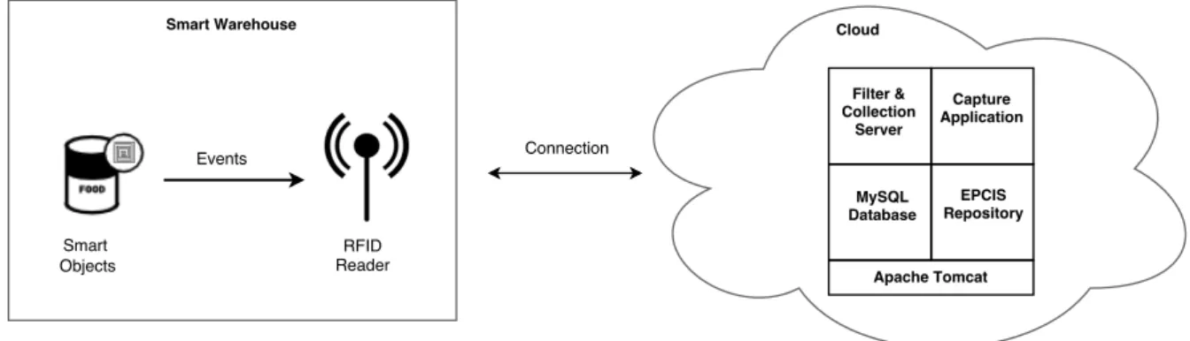
Smart Warehouse Deployment
Cloud Deployment
The reason we chose Docker containers over traditional VMs is that containers require less disk space and read/write (I/O) operations on the disk compared to traditional VM images [30]. In addition, Docker containers are easier to port to another infrastructure compared to traditional VMs because when a container requires the application and all its dependencies to be ported together, while the VMs require the entire application, guest operating system, binaries and libraries are being ported, which can be several gigabytes (GBs) in size.
Fog Deployment
The components responsible for storing data for a longer period of time are provisioned in the cloud. The components responsible for performing real-time processing of the data generated in the warehouse and the components that filter the data consumed locally and to be delivered to the cloud are provisioned in the fog. Both the smart storage as the fog can be connected respectively to the fog and the cloud through several types of connection, from a physical connection to a wireless connection.
Implementation Details
- Cloud Deployment
- Fog Deployment
The EPCIS repository is deployed and runs on top of an Apache Tomcat server instance. FCServer and the Capture application are deployed and run on top of a single Tomcat servlet instance. The Capture application sent the events collected by the FCServer to the EPCIS repository through the EPCIS Capture Interface.
Both the smart storage and the fog can be connected to the fog and the cloud, respectively, through several types of connection, from a physical connection (e.g. ADSL or fiber optic) to a wireless connection (e.g.
Summary
Latency Interaction
The information in the report can be used to notify the customer about an event in the smart warehouse or even to trigger a new event in the warehouse, such as opening or closing a door. The smart warehouse has a monitoring system that stores information about incoming and outgoing packages on the warehouse network. Thus, with the information provided by the monitoring system and the ALE module it is possible to calculate the delay requirement for an event that occurs in the warehouse.
With this methodology, we intend to obtain information about how communication time is consumed when an event is triggered in the repository for the deployment approaches described in Chapter 3.
Data Storage Performance
Evaluation Setup
Analyzing these metrics will allow us to compare the performance of the fog-based and cloud-based deployment approaches and help determine which one is more adequate to deploy the smart warehouse application. As for the software components, the application stack is composed of the Apache Tomcat 7.0.52.03 with Javaversion1.7.0 update79. The RFID middleware used was the Fosstrak (described in section 2.3.1.2) and the versions were: a) FCServer version1.2.0; b) Capture Application version 0.1.1; etc) EPCIS repository version 0.5.0.
Experiments Performed
Latency Interaction
- Cloud-based warehouse latency
- Fog-based warehouse latency
The expected behavior when configuring the ALE with a faster event cycle specification is that the event delay provides better overall performance. In the present experiment, the ALE module is configured with the Baseline ECspec and the Half Period ECspec. The graphs presented in Figure 4.4a and Figure 4.4b show that the ALE module is in an idle state during most of an event cycle.
When ALE is configured with the Half-period ECspec, the filtering and combining stage takes the most time, accounting for almost ≈ 73% of the total time.
Data Storage Performance
- Product pick up run
- Triple product pick up runs
With Baseline ECspect this stage occupies close to ≈ 95% of the total time, while with Half-period ECspect this value is close to ≈ 75%. For the standard and double query variations, they presented similar results - a maximum close to ≈2.5 megabytes (MB) - and its behavior tends to assume a linear pattern. Half of the range continues to present the highest values - maximum close to 18% - while the other variations show almost identical results - maximum close to 16%.
As in the previous experiment, the metricNetwork In system, shown in Figure 4.12, is very similar to the previous one in terms of its values and behavior.
![Figure 4.8: Robotic Warehouse demonstrator developed by Correia et. al [32].](https://thumb-eu.123doks.com/thumbv2/123dok_br/17602113.4189686/54.892.112.789.109.412/figure-robotic-warehouse-demonstrator-developed-correia-et-al.webp)
Results Analysis and Discussion
Interaction Latency
Data Storage Performance
To improve the provisioning of RFID application middleware in the cloud, we developed a mechanism based on Docker containers and the Chef tool that automates the installation and configuration of the modules that make up the Fosstrak RFID platform middleware. Regarding the system evaluation, we have defined two methodologies to estimate the latency of an event that occurs in physical space and data storage capacity for the Fosstrak platform. Regarding the data storage capacity of the RFID middleware, the results show that the Fosstrak platform is able to process the amount of data generated in the smart warehouse with acceptable capacity.
Furthermore, it is based on Docker container images for securing the application stack, is not specific to Fosstrak middleware, and can be extended to other EPCGlobal compliant RFID platforms.
Future Work
Since IoT covers several domains (as described in 2.1), in the future we want to perform a multi-domain evaluation to determine whether Utility Computing is suitable to deploy applications for these domains. By using cloud smart site infrastructure, we can reduce smart site operating costs, but application performance may be compromised. For future work, we want to perform an analysis to establish the relationship between the performance and the cost of a smart country in relation to its deployment approach: cloud, fog and local.
This analysis will allow you to choose the most appropriate approach to deploying a smart site based on application performance and smart site operating costs.
Cloud infrastructure for Smart Place applications
Palaniswami, "The Internet of Things (iot): A Vision, Architectural Elements, and Future Directions," Next Generation Computing Systems, vol. Floerkemeier, “From the Internet of Computers to the Internet of Things,” from active data management to event-based systems and more, p. in Ubiquitous Computing (IMIS), 2012 Sixth International Conference on, pp.
Jin, “Cloudthings: a common architecture for integrating IoT with cloud computing,” in Computer Aided Collaboration in Design (CSCWD), 2013 IEEE 17th International Conference on, p.
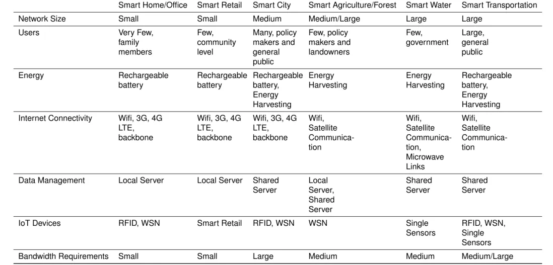
Smart Place application domains characteristics
Evaluation requirements
Event Cycle parameters
Cloud deployment: performance metrics results
Fog deployment: performance metrics results
IoT and Fog Computing
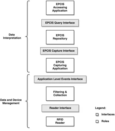
EPCGlobal Architecture Framework
Fosstrak architecture
Provisioning mechanism conceptual architecture
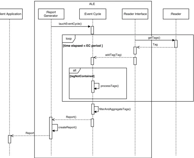
Provisioning Sequence Diagram
Provisioning mechanism architecture
Fosstrak containers stack
Cloud deployment: conceptual architecture
Fog deployment: conceptual architecture
RFID application setup
Cloud deployment: technological architecture
Fog deployment: technological architecture
Latency evaluation methodology
Data storage evaluation methodology
Latency Interaction sequence diagram
Cloud deployment: event latency breakdown
Cloud deployment: event processing breakdown
Fog deployment: event latency breakdown
Fog deployment: event processing breakdown
Robotic Warehouse demonstrator
CPU Utilization performance results
Network traffic performance results
CPU Utilization performance results
Network traffic performance results