Depending on the number and length of critical stretches, tight conditions may even call into question the feasibility of a TBM drive. Particular emphasis is placed on an adequate simulation of the interfaces between the ground and the shield or tunnel support.
Introduction
The present part of the report presents a qualitative discussion of the complex interactions between the soil, the tunneling equipment (TBM and support) and the support based on tunnel experience (Section 2) and theoretical considerations. We will refer to the features of different TBM types and emphasis will be placed on the interfaces between the three essential components of the system: soil, tunneling equipment and support (Section 3).
Magnitude of relevant deformations
In addition to the difficulties directly caused by squeezing behavior, adverse events such as clogging of the cutting head, insufficient reinforcement of the grips or instability of the working face or tunnel wall can also occur when drilling through weak soils.
The "time" factor
Sticking of the cutting head Cloaking of the shield Unacceptable convergence Damage to the tunnel support Jamming of the backup device. Attachment of cutting head: (a) high ground pressure; (b) extremely high core extraction rate; (c) Excessive torque demand in jammed or soft rock.

Thrusting system
In addition to unfavorable ground conditions, unpredictable stops due to technical problems (e.g. power cuts, mechanical breakdowns of the drilling machine, problems in the back-up system) must also be taken into account. Similar problems also arose with the grab reinforcement, filling of the segment lining and the telescopic part of the shield during the excavation of the Los Rosales tunnel (Colombia, double-shielded TBM, D = 3.54 m).
Back-up area
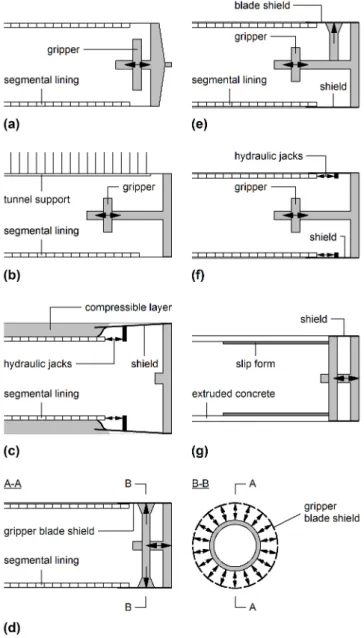
The discussion starts with the case of gripper TBMs (Section 3.1) because their greater flexibility in terms of tunnel support increases the complexity of the system. The case of single or double shielded TBMs impinging on a segmented liner will be discussed later in Section 3.2.
Gripper TBM
Overview of interactions
The location of the first installation of the tunnel support depends on the length of the cutting head and shield. The strength and load-bearing capacity of the tunnel support may depend on time (shotcrete, grouted screws).

Boring and thrusting
During standstill, the possibility of the TBM being pushed back by the axial earth pressure acting on the cutting head must also be considered. The rolling resistance of the cutter head depends on the soil {1-12} as well as on the characteristics of the cutters (eg, number, spacing, arrangement, shape, diameter, wear) {2-12}.

Tunnel support
Similar problems, as shown in Figure 7, can of course also occur behind the reserve area, i.e. after the passage of tunnel construction equipment. Choosing the type, amount and location of support is an important operational decision for the TBM grab drive.

Single and double shielded TBMs
The structural design of the segment lining plays an important role, as its load-bearing capacity limits the thrust force and torque that can be applied. Nevertheless, comparative studies should take into account the fact that double-shielded TBMs are generally longer than single-shielded TBMs.
Introduction
Choosing a larger drill diameter also reduces the risk of shield jamming. However, this will only be the case if this is combined with a larger overcut, i.e. with a larger gap between the tunnel wall and the extrados of the shield. 2-10}. As mentioned in Sections 2 and 3, both tunneling practice and theoretical considerations indicate that maintaining a high overall rate of advance may help solve the problem of the boring machine jamming due to soil compaction.
Pre-treatment or pre-support of the ground
In this regard, the heterogeneity of soil permeability must also be taken into account. In addition, the effectiveness of such a measure is small, because the openings in the cutting head do not, as a rule, allow a close spacing of the bolts.
Cutter head
Geometry
Korbin (1998) recommends a cutter overhang of 80mm beyond the mill head at the front and 50mm at the gauge. Keeping the size of the cutting head small in the axial direction reduces the area exposed to earth pressure and is therefore beneficial (Foster, 1997; Grandori and Antonini, 1994; Maidl et al., 2001).
Overboring
To avoid overstressing the measuring cutters (and especially their supports), the rotational speed of the cutter head and the thrust force must be reduced during the overboring {8-7, 8-9}. Such a test was carried out in the Bodio section of the Gotthard base tunnel (Switzerland).

Shield
In addition, the TBM drive was hampered by clogging of the cutting head (Babendererde, 1989) and was repeatedly damaged (Klonsdorf and Schaser, 1991). The design of Gotthard machines made it possible to reduce the diameter of the shield to 20 cm.
Thrust force and torque
Back-up equipment
Tunnel support
Practically rigid supports
A correct and fast-acting embedment of the segment cladding is very important for its load-bearing capacity. Furthermore, the load on the tunnel support in the machine area increases with the advancement of the tunnel surface, and this happens simultaneously with the hardening of the shotcrete.
Yielding supports
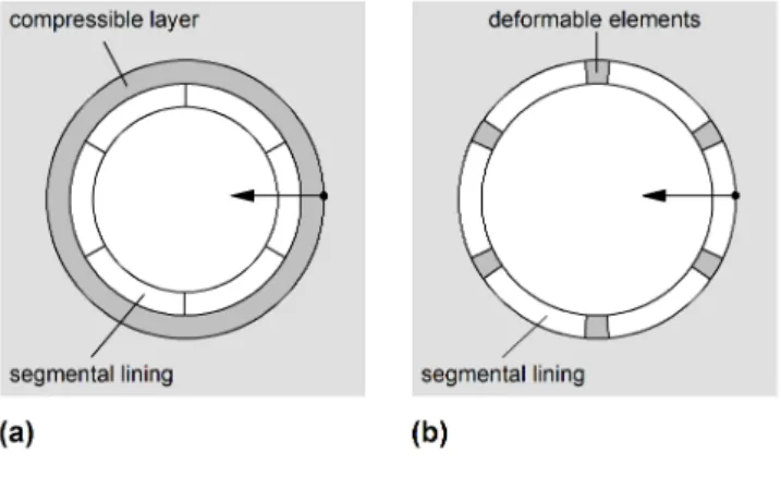
Brunar and Powondra (1985) reported on the development of the so-called "Meypo deformable elements", which are to be placed in the longitudinal joints of a segmental liner and enable a reduction of its circumference by 1.80 m (6 joints, each of which experiences a compression of 30 cm). The Meypo deformable elements were installed in a tunnel in the Ibbenbüren coal mine in Germany at a depth of approximately 1500 m (inner diameter of the segmental lining 9.47 m).
On the appropriate support concept
Should it be necessary to further increase the resistance of the segmental lining (beyond the resistance offered by segments of manageable thickness and weight), it is possible to design a lining system consisting of two concentric segmental rings (Figure 15). The length of the double shield is potentially disadvantageous with respect to the risk of entrapment.
Analytical solutions
Empirical relationships
A significant degree of engineering judgment is required in cases like this – unlike shielded TBMs where the support is basically pre-determined (precast segment lining). 2008) evaluated the earth pressure and thrust force requirements in their empirical study of the double-shielded TBMs from the Ghomroud Tunnel (Iran, D = 4.50 m) and the Nosoud Tunnel (Iran, D = 6.73 m). The performance of TBMs in squeezing ground can also be assessed by evaluating and correlating the operational parameters of the TBM.
Numerical investigations
A recent description of the calculation method (including its further development for poro-elastoplastic materials) and numerical comparisons with the step-by-step simulation of a continuous tunnel can be found in Anagnostou (2007a, 2007b) and Cantieni and Anagnostou ( 2009a), respectively. For the commonly chosen, computationally tractable round length values of s = 1–2 m, the step-by-step method leads to a significant underestimation of the shield and liner load (Cantieni and Anagnostou, 2009a).
Constitutive model
The research involves axisymmetric modeling of the excavation of a deep cylindrical tunnel through a homogeneous and isotropic subgrade subjected to a uniform and hydrostatic initial stress (Figure 2). The assumption of a uniform initial stress field assumes that the change in the initial stress in the vicinity of the tunnel is small compared to the average stress prevailing on the axis of the tunnel.
Tunnel boundary conditions
Shield
This so-called "conicity" of the shield is realized by a step-by-step reduction of the diameter of the shield (Herrenknecht, 2010). A numerical example illustrating the effect of shield taper will be discussed in Section 4.3.
Tunnel support
For example, if the conicity of the shield is realized in two stages (Figure 5), the non-uniform mixed boundary conditions in equation 1 read in a general way as follows:. A numerical example illustrating the effect of the shield conicity will be discussed in Section 4.3. or a segmented liner that is immediately backfilled).
Simplified model
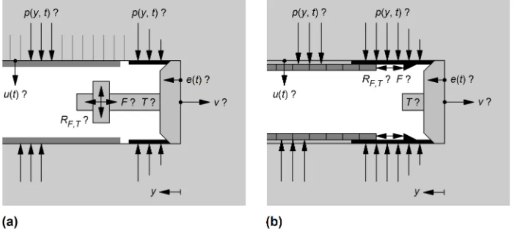
As will be shown later in Sections 4.4 and 6.3, detailed simulation of the behavior of the tunnel support is also important for analyzing its interaction with the shield. In this context, it is important to note that the installation point and the stiffness of the tunnel support are not only essential for its load, but also for the pressure that develops on the shield (section 4.5).

Shield-ground interaction
Furthermore, Section 4.4 quantitatively discusses the simplified model for the shield-soil interface mentioned in Section 3.2.3 and shows how important it is to consider the geometric properties and the installation sequence of the shield and the tunnel as realistically as possible . support. The load concentration at the end of the shield can be traced back to the complete unloading of the tunnel boundary at the installation point of the liner.

Overstressing and stress history of the ground
Earth pressure increases with distance from the tunnel face as the stabilizing effect of the core in front of the face becomes less pronounced. As the tunnel excavation approaches, the axial stress yy decreases in front of the tunnel face, while a stress concentration occurs in the radial and tangential directions (Figure 8a).
Thrust force
The positive effect of the "stepped" construction of the shield becomes obvious when we compare the average ground pressure ps (which determines the required thrust force) acting on the shield (Figure 9). It is reduced by 16% and 28% respectively if there are two or three steps in the shield construction.
A simplified model of shield-ground interaction
A large gap is more important for the back of the shield because ground convergence increases with distance behind the face. The latter requires a numerical solution of the finite element equations for each value of the shield length L, while the simplified model makes it possible to calculate the curve Fr.(L) on the basis of a single numerical calculation.
Shield-support interaction
It is therefore important to model the characteristics and the installation point of the tunnel support as accurately as possible, not only from the perspective of structural assessment, but also in relation to the design of the TBM.
Introduction
During the first 3 km of TBM operation, the squeeze caused shield jamming in several cases, although the depth of cover was quite moderate (about 120 m, i.e., an estimated initial stress of 0 = 3 MPa). Due to the variability of squeezing phenomena, attention has been paid to the specific situation that prevails in some critical areas.
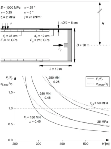
Investigations on TBM optimization
A main goal of the studies was therefore optimization of the second TBM to be able to cope with pinching. The combination of all these measures would move the critical curve from curve A to curve B in the lower left corner of the diagram, meaning that an improved TBM would be able to cope with adverse conditions such as those encountered by the first TBM at a coverage depth of H = 120 m.
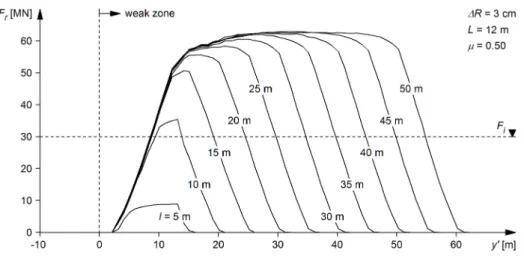
Effect of short weaker zones
Maximum required thrust Fr in the weak zone as a function of their length l (radial gap size R = 3 cm, shield length L = 12 m, skin friction coefficient = 0.50, safety factor for the required thrust SF = 1.0 other parameters according to table 1, set 4). As expected, the required thrust increases as the TBM enters the weak zone and decreases as the TBM exits it.
Introduction
For long fracture zones and a step length of s = 0.5 m, the results of the stepwise solution are in good agreement with those obtained with the steady-state method. Deformations of up to 10 cm occurred within the short interval between the working plane and the tail of the shield, which consumed most of the convergence margin of the shield articulation, but without immobilizing the TBM.
Investigations
All support types include steel sets (TH 36) at 1 m intervals and with sliding connections for yielding support systems. Characteristic lines (soil pressure p as a function of the radial displacement of the lining ul) of the investigated support systems (cf. Table 3).

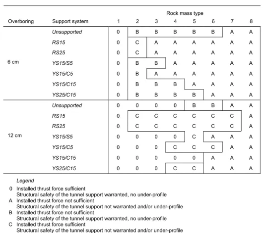
Discussion of the results
The structural safety of the tunnel support is guaranteed, no low profile A The installed driving force is not sufficient. The structural safety of the tunnel support is not guaranteed and/or under profile B The installed driving force is not sufficient.
Axial symmetry
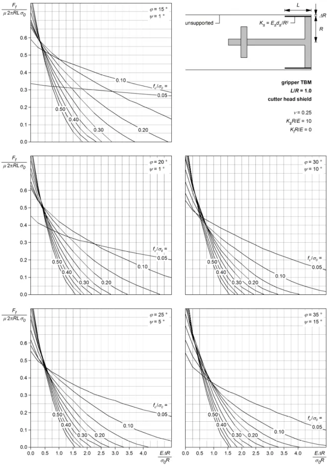
The most significant consequence of the assumption of axial symmetry is that only normal forces are seen to develop in the shield and lining, whereas in reality bending may also occur. Given the purpose of the design nomograms (which is to estimate thrust force requirements), however, it is sufficient to determine the total earth pressure acting on the shield.
Variability of the ground
Due to the assumption of axial symmetry, the resulting pressure is "homogenized" across the tunnel cross-section, because the model assumes an overcut that is constant around the circumference of the shield, when in reality the shield is constant. slides along the tunnel floor, which means that the overcut above the center is greater than in the lower part of the tunnel cross-section. Another consequence of the assumption of axial symmetry is that the response of the model screen and liner tends to be stiffer than it actually is, and this should lead to an overestimation of the ground pressure and of the necessary thrust.
Time-dependency of ground behaviour
It should be noted that rapidly evolving convergences have been observed in a number of tunnels in the past (see Part I).
Constitutive model
The construction nomograms presented in this report are therefore also applicable to the structural design of the shield. Results of numerical investigations related to single shielded TBMs with normalized shield length L/R = 2.0: (a) normalized required thrust force Ff* as a function of E/0 for different values of R/R; (b) normalized required thrust Ff* as a function of the product of E/0 and R/R.
Shield stiffness
It can be noted that the overestimation of Ff* can be quite relevant in the case of thin shields or an earth with a high Young's modulus E.
Lining stiffness
Machine layouts
Technical data of different TBMs depending on the bore diameter D: (a) ratio Ds/D between cross section Ds (in diameter) and bore diameter D; (b) the ratio Dl/D between the annular gap Dl (in diameter) and the bore diameter D; (c) normalized shield length L/R. Technical data of different TBMs depending on bore diameter D: (a) installed thrust Fi; (b) applied gripper force Fg,i; (c) installed torque Ti.

Determining the required thrust force
In addition, it should be noted that the cross-section (along with the taper of the shield) must first allow the TBM to be steered. In this regard, some reserve should be made when using nomograms (ie, the reduced size of the radial gap R should be entered into the calculations).

Vulnerability with respect to ground variations
H Tire depth f By installing removable hydraulic auxiliary jacks L Length of shield g Figure 7 and Figure 8 (linear interpolation) Lf Length of front shield h Maximum possible downforce. Lr Length of the rear shield in Skin friction coefficient = 0.25 (with lubrication of the shield sheath), after.

Bodio Section of the Gotthard Base Tunnel (Switzerland)
For simplicity, Table 3 reports only the results regarding thrust requirements for restarting the machine after standstill.
Faido Section of the Gotthard Base Tunnel (Switzerland)
Uluabat Tunnel (Turkey)
Section 4 of the Pajares Tunnel (Spain)
Wienerwald Tunnel (Austria)
Guadiaro – Majaceite Tunnel (Spain)
Guadarrama Tunnel (Spain)
Fa Thrust (auxiliary system, installed) Dl Annular gap (in diameter) e Front part of shield m Rear shield. Geometric illustration of the transformation of equation 3 (at a steady state, the curve A*(y*) moves with the speed v in the direction of the tunnel); after Anagnostou (2007a).
Distribution of the pore water pressures
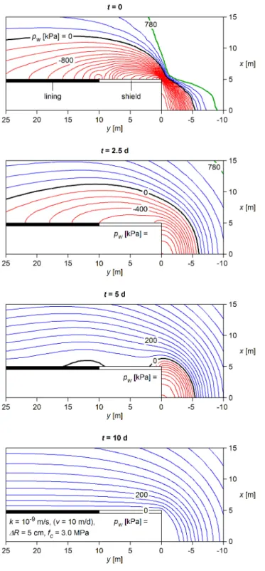
The role of excess pore pressure distribution and the effect of the ratio of advance rate v to soil permeability k (cf. Section 2) will be analyzed by means of numerical calculations regarding the hypothetical case of a 400 m deep tunnel that passes through weak ground at a depth of 100 m below the water table. With a decrease in the speed of advancement (or with an increase in soil permeability), the distribution of excess pressures becomes faster, i.e., closer to the direction of the tunnel.
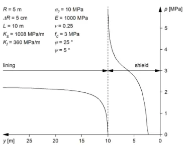
Interaction between shield, ground and support
Contour lines of the pore pressure pw for different values of the ratio of the speed of travel v to the permeability of the soil k (radial gap size R = 5 cm, uniaxial compressive strength of the soil fc = 3.0 MPa; other parameters according to Table 1). Results of numerical calculations for a radial gap size of R = 5 or 10 cm (left and right, respectively) and for different ratios of propulsion speed v to soil permeability k: (a) radial displacement u of the soil at the tunnel boundary; (b) convergence u – u(0) of the drilled profile;. c) earth pressure p acting on the shell and cladding; uniaxial compressive strength of the soil fc = 3.0 MPa; other parameters according to Table 1.

Calculation of thrust force
The feasibility and reliability of such a large overshoot is however questionable and should be carefully checked for the given project conditions (cf. Part I). Here the coefficient of skin friction is taken to be 0.30 and 0.45 for sliding and static friction, respectively (Gehring, 1996).
Effects of overboring and lubrication
The two operating phases mentioned above are also different with respect to the skin friction coefficient. During ongoing excavation, the TBM must overcome sliding friction, while static friction must be considered when restarting the TBM.
Effects of permeability
For example, the extensive laboratory test program carried out to study the kakiritic rocks of the Gotthard Base Tunnel (Lot Sedrun) in Switzerland showed a permeability between 1.5 x 10⁻⁹ and 1.1 x 10⁻¹⁰ m/s (Vogelhuber , 2007).
A counter-intuitive aspect of model behaviour
This large sensitivity in the numerical results indicates a significant source of prediction uncertainty. is associated with the previous deformations of the ground in front of the face. A similar effect can also occur in the case of creep, when the core still behaves elastically, while the rest of the tunnel already experiences plastic deformations.).

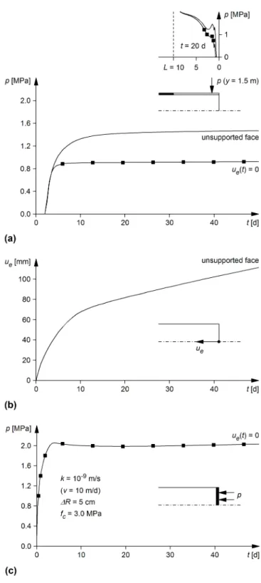
Extrusion rate of the core
Since this numerical example concerns rather unfavorable conditions (in terms of soil strength and cover depth), the results support the hypothesis that the excavation speed is usually high enough to avoid problems with deformations of the working surface (Barla, 2001; . Gehring, 1996; Hoek, 2001). .
Role of tunnel diameter
The diagram shows the rate of use of the thrust force as a function of soil permeability k. For the reasons mentioned above, the benefit of increasing the overcut (from R = 5 to 10 cm in this example) is greater in the case of the smaller diameter tunnel.
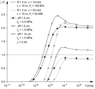
Dissipation of the excess pore water pressures
The diagram deals with the thrust requirements for TBM restart, i.e. to overcome static friction (and, according to Equations 5 and 6, Fr = Ff). In a low strength and high permeability soil (fc = 1.5 MPa, k > 10-8 m/s) the thrust requirements will be critical for both machines in the case of a normal overcut (R = 5 cm).
Longitudinal arching in the shield area
The convergence and pressure distribution are completely different in the case of the larger overcut (right side of Figure 15). On the other hand, arching increases the soil pressure behind the shield and can compromise the structural safety of the lining.
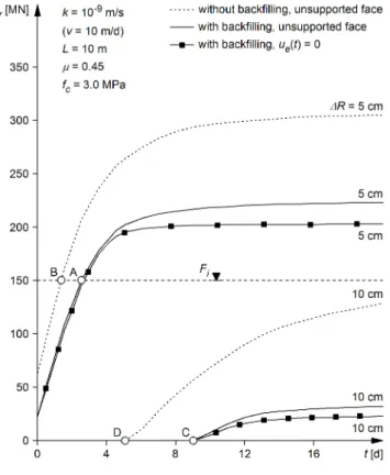
Effect of backfilling of the segments close to the shield
The front and rear parts of the shield remain unloaded due to the supporting action of the liner and core, respectively. On the one hand, filling the segments immediately behind the shield facilitates longitudinal bending and reduces shield loading.
Load transfer to the core ahead of the face
For rapid excavation through a low permeability soil (i.e. for a high v/c ratio), where undrained conditions prevail in the shield region and the earth pressure p acting on the shield at the start of the stop is very low. (see curves for t = 0 in Figure 16b), it seems to be beneficial to delay the refilling of the segments. However, it should be noted that improper augmentation of the segments can reduce the bearing capacity of the liner and therefore limit the effectively available thrust (it may be impossible to utilize the installed thrust).
Thrust force needed for restarting TBM operation
Ek entity of N2 diagram (the subscript k refers to the entity numbering) El Young's modulus of the lining. Lf the length of the front shield (double shielded TBM) Lr the length of the rear shield (double shielded TBM).