Different deformation microstructures associated with deformation imprints identified in quartz-feldspar rocks of the Krušné gora (talk) Central European Tectonic Group (CETEG) 2018. The main part of the first chapter is focused on the work of previous authors in the central part of the Erzgebirge.
Individual units and their evolution according to two similar tectonostratigraphic
- Hypothesis 1
- Hypothesis 2
- Important features resulting from hypotheses
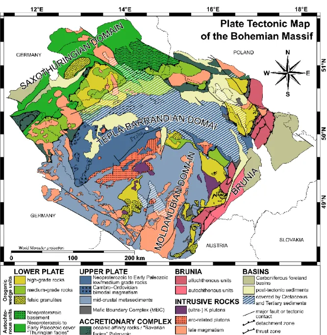
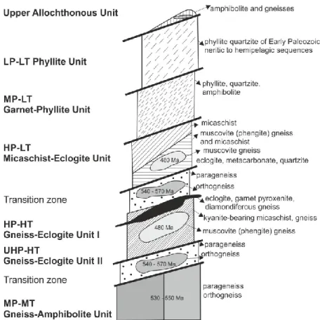
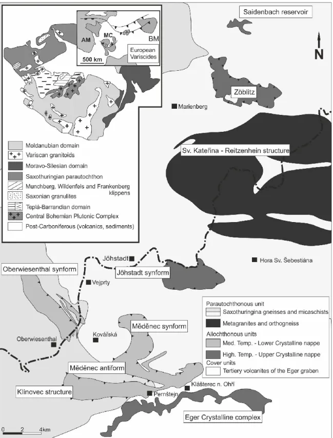
The critical feature is the defined lithological zoning in the central part of the Erzgebirge (Konopásek et al., 2001). In figure 6 (Collett et al., 2020) the significant protolith ages are shown with the information about the method (shape) and reference (number).
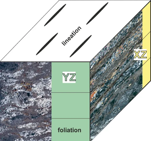
We studied more than 200 XZ (parallel to lineation and perpendicular to foliation) or YZ (perpendicular to lineation and foliation) ( Fig. 7 ) thin sections of the finite strain ellipsoid from 47 locations throughout the study area. Figure 10 Phase mapping of the entire thin section (left side of the image) with elemental mappings (right side of the image).
Structural record
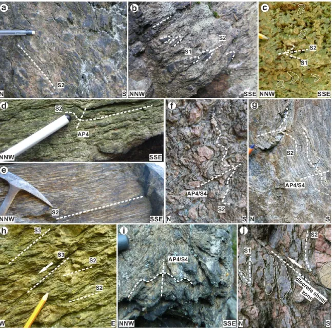
In the immigrant units, D2 overprinted a previous flat fabric S1 identified in remnants of isoclinal folds (Fig. 13b,c,j). These shear zones generally have a N-S trendline and show top-north kinematics (Fig. 13j).
Deformation microstructures
- Grain size analysis of the S2 related microstructures
- Mineral chemistry and P-T conditions of studied microstructures
- Crystallographic orientations of quartz and feldspars
- Microstructural types in relation to deformation fabrics
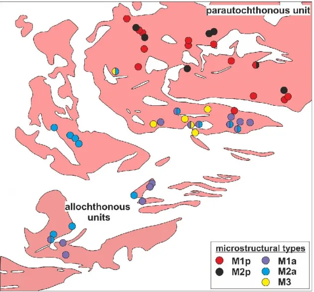
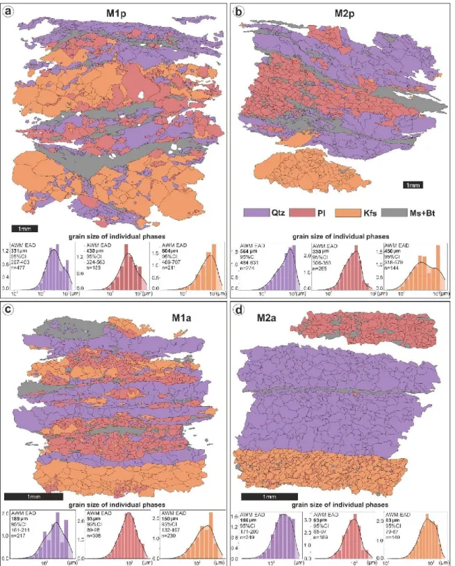
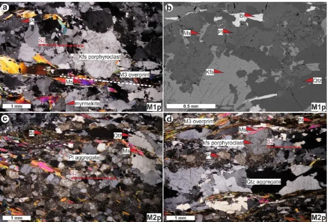
The M1p microstructure is typically associated with weakly developed foliation in S2 low-stemmed domains of the parautochthonous unit (Fig. 14). The M1a microstructure dominates in the southeastern part of the studied area, where it overlaps with both M2a and M3 (Fig. 14). Quartz in M1a shows more heterogeneous grain size distribution (histograms in Fig. 16c and d) probably due to an overprinting of M1a by M2a.
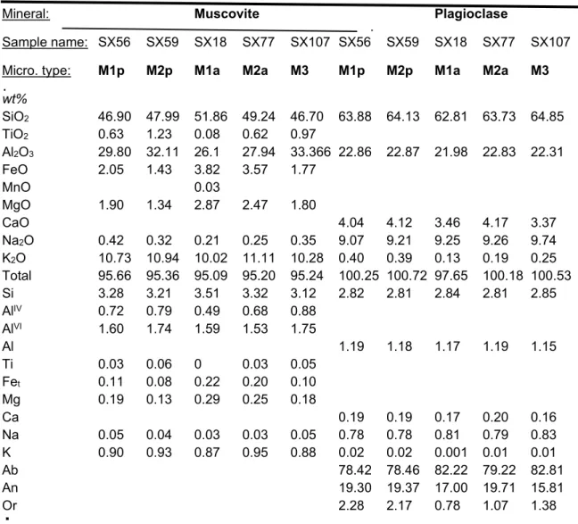
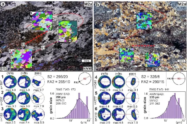
The black line in the histogram corresponds to the kernel density estimate (KDE) of the probability density. The lowest values of albite in plagioclase (Ab72) and the highest in K-feldspar (Ab12) were documented in the large grains of the M2a microstructure (Fig. 18c-d). The M1a and M2a microstructures, characterized by the grain size of recrystallized K-feldspar aggregates, can be observed locally in the same thin section (Fig. 20c).
The corresponding CPOs are shown in the section perpendicular to S2 and parallel to the F2 folding axis.
Documentation of studied outcrop
The studied outcrop, Mnišská skála, is a complex of several 10-60 meter rocks (Fig. 23) formed by quartz feldspathic rocks - banded orthogneiss, mylonite and granofels. The outcrop is part of a larger occurrence of orthogneiss that has been assigned to the HP unit 2 (Schmädicke and Evans, 1997; Rötzler and Plessen, 2010) or to the upper crystalline nappe (Konopásek and Schulmann, 2005, see also Fig. 22 ).
Structural record
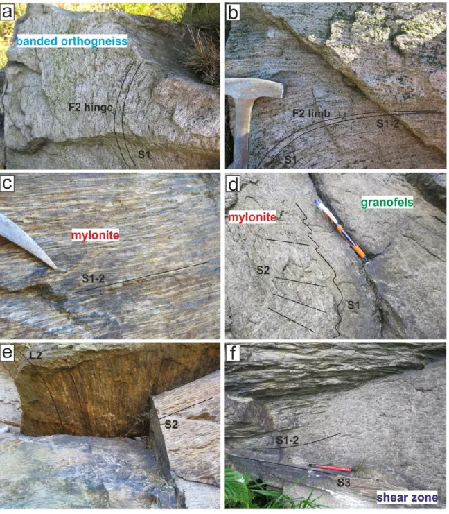
S1 is affected by open to isoclinal folds where S1 becomes parallel to S2 in high-strain D2 domains (Fig. 23b). The original S1 band in the limb has been intensively overprinted by planar axial cleavage S2 which resulted in the development of the S1-2 composite fabric (Figs. 23c and 24b). The F2 folds are strongly non-cylindrical as indicated by the curved shape and distribution of the gentle S-to-ESE intersection line, L2 (Figs. 23d and 24e).
S2 cleavage as well as overprinted S1 in fold limbs generally show ESE-dipping stretch line L2. S2 dips gently to the S or E, and it is locally obliquely cut by localized shear zones S3 (Figs. 23d, 24f). Despite the lack of L3 in the shear zones, deflection of S2 in their vicinity suggests a normal sense of motion.
24 Deformation structures identified at the site (for location of photographs see Fig. 23): a) F2 hinge in the steep S1 fabric on an example of the banded orthogneiss; b) composite S1-2 fabric derived from S1 banding from the limbs; c) subhorizontal and gently dipping S1-2 of mylonite showing monomineral bands of K-feldspar and quartz; d) transposition of steep S1 to subhorizontal axial cleavage S2 and transitional appearance of mylonite and granofles; e) curved shape of intersection lines L2, documenting the non-cylindricity of F2 folds; f) deflection of subhorizontal fabric S1-2, suggesting the normal sense of motion on the S3 shear zone.
Mineral composition and microstructures of studied rocks
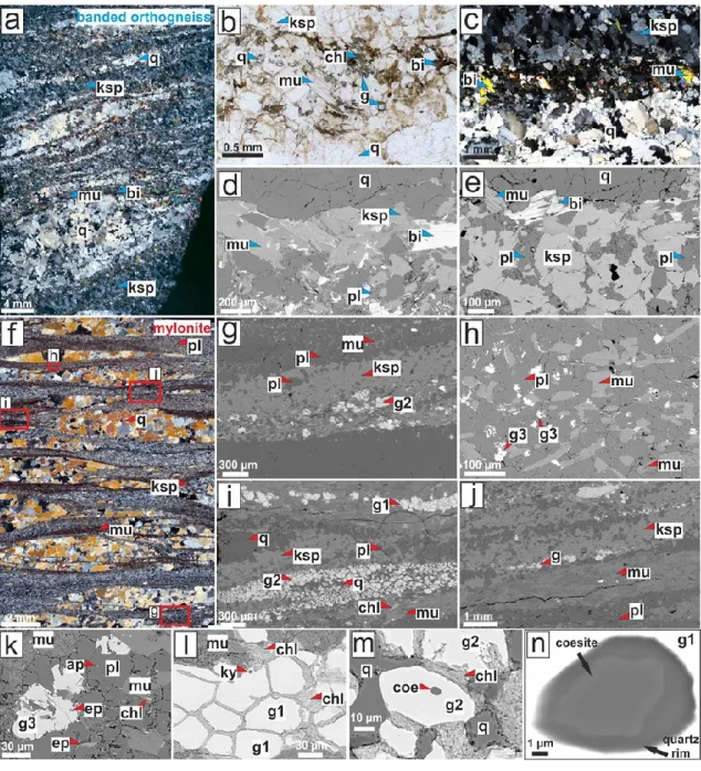
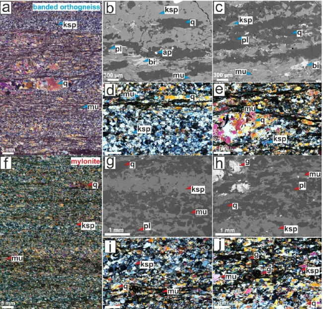
White mica bands commonly occur at the contact with quartz aggregates and show strong shape, preferred orientation of individual grains (Fig. 25f and j). The white mica bands are sometimes mixed with chlorite and locally intercalated by thin bands of garnet of variable grain size (~60 to 120 µm) (Fig. 25i). The K-feldspar bands are commonly surrounded by thin plagioclase bands (Fig. 25g, i), where the relationships between K-feldspar and plagioclase suggest replacement of K-feldspar.
Similar to banded orthogneiss, mylonite also contains thin bands of mixed quartz, plagioclase, K-feldspar, muscovite, chlorite and garnet (Fig. 25g). On a macro scale, granofels appear isotropic, however on a micro scale a weak fabric defined by the spatial arrangement of individual mineral phases can be identified (Fig. 27a). Compared to orthogneiss and banded mylonites, the microstructure of granofels is characterized by a mixture of relatively large grains of quartz (~500 to 1500 µm), K-feldspar (~300 to 2000 µm), plagioclase (~500 µm) and garnet (~ 1400 µm). ), and scattered smaller grains of mica and white biotite (Fig. 267-c).
Orthogneiss in S3 shear zone shows thin monomineral bands of recrystallized quartz and mixed bands dominated by either K-feldspar or plagioclase with dispersed muscovite, biotite and small garnet grains (~150 µm) (Fig. 27d–f).
Chemical composition of minerals
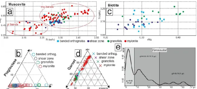
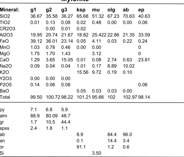
Compositional profiles across representative garnets from these rock types revealed a slight increase in rim in grossular and decrease in almandine in banded orthogneiss while the opposite was observed in granofels (Fig. 29a,b). As seen in this diagram, the spessartine content is low and uniform, 1–4%, and is represented here as Sps+Pyr; e) Estimation of the Gaussian kernel density in the mylonite sample from the whole garnet analysis with reference to the three garnet groups based on the grossular component. Garnet in mylonite alm41-92,gr2-55,py+spss2-10 is characterized by different proportions of almandine/grossular components (Fig.28d), which however do not vary significantly between individual garnet grains (Fig.29c-e). .
Chemically different types of garnet were documented by Gaussian kernel density estimation applied to all analyzed compositions of garnet in mylonite. Just like plagioclase and white mica, the three types of garnet also correlate with specific mineral composition. Of the three garnet types, g1 and g2 show rather flat compositional profiles with a slight rimward increase in grossular offset by decreases in pyrope and almandine while g3 shows a rimward increase in almandine and decrease in grossular tone (Fig. 29c-e).
It is important to note that g1 and g2 contain kyanite and coesite inclusions, while g3 contain epidote inclusions (Fig. 25k–m).
Domainal composition of mylonites and equilibrium mineral assemblages
Phase equilibria modeling
The calculated pseudosection for Ca-poor domains in mylonite (WR1) is shown in Fig. The early relict metamorphic assemblage is constrained by the coexistence of coesite and g1 in the sample, consistent with the large field above. Contrary to observations, the coesite-bearing field is associated with coexisting jadeite clinopyroxene, which was not observed in the sample.
On the other hand, the presence of kyanite as inclusions in g1 contrasts with its lack in this P-T range in the calculated pseudosection. Alternatively, its presence can be explained by a local excess of Al in the band of phengitic muscovite surrounding g1 grains (Figs 25i and 30d). Although such an assembly is not in equilibrium in the calculated pseudosection, it may reflect a partial transformation of the UHP assembly during decreasing pressure.
In the calculated pseudosection, the decreasing pressure indicates an increase in grossular component in garnet, a decrease in Si in muscovite and formation of plagioclase (Fig. 31).
Principal Component Analysis in the mylonitic sample
PCA analysis clearly shows thin-section scale variation in composition, which is manifested by a decrease in K2O and an increase in CaO, Na2O, and Al2O3.
Documentation of studied outcrop
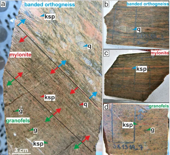
35 Simplified sketch of the main domains, lithology distribution and deformation fabrics found and described at the Hohenstein locality. The peculiarity of this particular locality is the presence of the transition between banded orthogneiss, mylonite and granofels at the meter scale of an outcrop wall, from where the samples for the thin section were collected by cutting the continuous slab over the three rock types (Fig. 35b, Fig. 36a, Fig. 37). The outcrop conventionally belongs to unit HP 2 (Schmädicke and Evans, 1997; Rötzler and Plessen, 2010) or the upper crystalline part (Konopásek and Schulmann, 2005, see also Fig. 34).

Structural record
The sample of the slab used for a) banded orthogneiss with visible augens of quartz; b) mylonite, where the spacing bands for K-feldspar are shown;.
Mineral composition and microstructures of studied rocks
Granofels is described as a relatively fine-grained granoblastic rock composed of a mixture of K-feldspar, plagioclase, quartz, white mica, biotite and garnet. In the microscale, a weak fabric is visible, which is determined by the spatial distribution of individual mineral phases (Fig. 39a). The mineral phases are relatively homogeneously distributed over the thin section and the grain size of the same minerals is also quite consistent.
Quartz grains are slightly smaller compared to mylonite and banded orthogneiss with grain size around ~200-800 µm. 39 Deformation microstructure of granofles from the Hohenstein locality showing a) the distribution of mineral phases and textural appearance; b) garnet grains surrounded by a mixture of quartz, plagioclase, K-feldspar and mica.
Chemical composition of minerals
The last significant deformation event in the Erzgebirge is associated with the large-scale D4 folding and doming of the entire region. The microstructural overprint in orthogneiss of parautochthonous and allochthonous units in the Erzgebirge subduction complex reflects their continuous deformation during exhumation along two opposite P-T paths. Contrasting microstructures in the parautochthonous and allochthonous units allowed us to localize their boundary further towards the core of the Kateřina-Reitzenhain Dome than previously thought.
This event resulted in the final excavation of the Kateřina-Reitzenhain dome exposed at the core of a large-scale antiform. Model for syn-convergent extrusion of orogenic lower crust in the core of the Variscan belt: implications for exhumation of high-pressure rocks in large hot orogens. From orthogneiss to migmatite: Geochemical assessment of the melt infiltration model in the Gföhl Unit (Moldanubian Zone, Bohemian Massif).
New constraints on the tectonometamorphic evolution of the Erzgebirge orogenic wedge (Saxothuringian Domain, Bohemian Massif). First discovery of coesite in the ultrahigh-pressure metamorphic area of the central Erzgebirge, Germany. Baltica- and Gondwana-derived sediments in the Middle German Crystalline Rise (Central Europe): Implications for the closure of the Rheic.

117