Analysis of Photovoltaic Fed Partially
Isolated Three-Port Full Bridge Converter
with the Centralised Controller
Venmathi M #1, Ramaprabha R*2 #
Department of Electrical and Electronics Engineering, SSN College of Engineering, 603 110, India 1
venmathieee@gmail.com *
Department of Electrical and Electronics Engineering, SSN College of Engineering, 603 110, India 2
ramaprabhar@ssn.edu.in
Abstract— In this paper analysis of an efficient topology of the three-port full bridge dc-dc converter is presented. This topology is promising with the view points of centralised control, compact design as it is capable of interfacing many numbers of ports with less number of switches, low cost, simple and fast power flow management with reduced conversion process. In a stand-alone system this topology is used to interface renewable energy sources and the load along with the energy storage device. Thus the proposed topology interfaces three ports: as one source port, one bidirectional storage port and an isolated output port. The key feature of this converter is that it performs buck-boost operation on the input port side to obtain power balance in the system with the centralised controller. The centralised controller was implemented by using proportional Integral (PI) controller. Such that it is used to track maximum power from the Photovoltaic (PV) system and to regulate output voltage by controlling the charging and the discharging characteristics of the battery. Zero voltage switching (ZVS) is also achieved in all the switches by using the energy stored in the leakage inductance of the transformer, output filter inductance and capacitance.
Keyword- Zero voltage switching, Three-port full bridge converter, PI control, PV system, Power balance. I. INTRODUCTION
As the demand for the power generation increases day by day, to meet this energy crisis many researchers were focusing their interest on the generation of power from the renewable energy sources like fuel cell, wind energy conversion system, photovoltaic system etc. The future power system interfaces all these sources with the load along with the energy storage device. In case of the stand-alone system the storage device is required to provide backup power and for the fast dynamic response. To interface the sources which are intermittent in nature a multi-input dc-dc converter is proposed [1]-[3].The conventional multi-input dc-dc converters for interfacing many renewable sources use a common dc link which has the drawbacks like requirement of more number of conversion devices, complex design and it is applicable only for the low power application.
In order to overcome this drawback multi-port topology is proposed [4] which treats the entire system has single converter and it has many key features like centralised control, compact design with less number of switches, reduced conversion stages, fast and simple power flow management. This multi-port topology is used in many applications like UPS remote communication system, satellite applications, traffic lights, multi-voltage-bus electrical vehicles, systems with multiple regulated outputs, domestic applications etc.
Multi-port converter can be realized by using different topologies like non-isolated topology, isolated topology and partially isolated topology [5]-[7]. Non-isolated topology shares a common ground which can be obtained by buck, boost, buck-boost topology etc. But the main drawback of using this topology is voltage levels of all the ports are not flexible, increased cost and it is characterised only by hard switching. The fully isolated topology is obtained by using full-bridge or half-bridge topology connected by means of magnetic coupling [8]-[10]. This topology provides voltage flexibility has each port has its own reference and it also characterised by soft switching. But the main drawback in this particular topology is the usage of many number of active switches and it involves the complex driving circuitry.
The main impact of this paper is to interface the PV system to the three-port full bridge converter and to analyse the performance of this converter with various insolation and different loading condition. ZVS is also achieved for all the switches with various duty cycle. The paper is organised in such a way that Section II deals about the design and the operating principle of three-port full bridge converter with ZVS analysis. Section III discuss in detail about the equivalent circuit and the mathematical model of the PV system. Section IV describes about the control structure of the three-port converter with results and discussion in Section V and ends up with conclusion in Section VI.
II. DESIGN AND OPERATING PRINCIPLE OF THREE-PORT FULL BRIDGE DC-DC CONVERTER
The circuit diagram of the partially isolated three-port converter consisting of two input port and one output port is shown in Fig. 1. The input ports are characterised as source port and the storage port which is being connected to the PV system and to the battery. The output port is characterised as the load port. The inputs are connected to the load port via transformer and by the full bridge
diode rectifier.
Fig. 1. Partially isolated three-port full bridge converter
This converter consists of two switching cells with each switching cells consisting of two switches as S1and S2 in one cell and S3 and S4 in the other cell. The PV system and the storage device have been connected to these two cells. Power transfer between these two switching cells takes place by means of magnetising inductor Lm. As the voltage applied to the primary of the transformer depends on the magnetising inductor, the magnetising inductor Lm has to satisfy due to the volt second balance principle.
According to the availability of the supply and the load demand the three-port system is capable of operating in three different modes such as dual output (DO) mode, dual input (DI) mode and single input single output (SISO) mode and its corresponding operation is shown in Table I. Such that the power balance is maintained in the system which is given by equation (1).
o P b P PV
P = +
(1)
TABLE I
Modes of Operation of the Proposed Three Port Converter
Modes of operation Availability of PV Power
Condition of battery/Availability of battery power
Dual output mode, DO Po PV
P ≥ Battery charges, 0
b
P ≥
Dual input mode, DI &Ppv 0 o
P PV
P ≤ > Battery discharges, 0 b
P ≤
Single input single output mode,
SISO PPV =Po Battery discharges, Pb =−Po
The system operates at the frequency of 100 kHz and each switching cycle consists of four switching states. During this operation the contribution of the power to the load takes place either from PV system or by the storage device or by both the input ports. Table II gives the clear picture about the operations involved in each switching state. The corresponding waveform at different switching state is given in Fig. 2. Under each switching state the current flowing through the transformer primary is given by the equation.
Lo ni Lm i p
TABLE II Switching State Operation
Parameters Switching state 1 Switching state 2 Switching state 3
Switching state 4 Corresponding
time period t0-t1 t1-t2 t2-t3 t3-t4
Operating
Switches S1 and S4 S1 and S3 S2 and S3 S2 and S4 Source
contributors PV system PV system and battery battery none Polarity of
voltage applied to the
transformer
positive positive negative Not applicable (zero)
Governing
Equations m
L b V PV V dt Lm di − = o L o V ) b V pv n(V dt Lo
di − −
= m L b V PV V dt Lm di − = o L o V ) b V pv n(V dt Lo
di − −
= m L b V dt Lm di − = o L o V b nV dt Lo di − = 0 dt Lm di = o L o V dt Lo di − =
Fig. 2. Corresponding key waveforms at different switching states
TABLE III
Parameters of the Three-Port Converter
Parameters Values
PV voltage, Vpv 76 V
Battery voltage, Vb 38 V Required output voltage, Vo 42 V
Turns ratio,n 3:4
Switching frequency, fs 100 kHz Capacitance, Cpv, Cb, Co 470 µF Transformer Inductance, Lm 70 µH
TABLE IV
Values of the Various Parameters of the Converter in Different Operating Modes
Dual output
mode Dual input mode
Single input single output mode
VPV > Vb VPV < Vb VPV = 0 Battery = 38 V Battery =38 V Battery =38 V
ILM = 0.272 A ILM = -44.94 A ILM = -60.78 A S1,Id = 1.52 A S1,Id = 24.95 A S1,Id = 55.15 A S1,Vds = 62.76 V S1,Vds = 6.198 V S1,Vds = 0.5337 V
ILo = 2.619 A ILo = 0.39 A ILo = 0.039 A Vp = 41.31 V Vp = 7.422 V Vp = 1.183 V Vs = 49.59 V Vs = 8.913 V Vs = 1.433 V Vo = 47.15 V Vo = 7.026 V Vo = 0.705 V Po = 123.5 V Po = 2.742 V Po = 0.0276 V
When the PV voltage is less than the battery voltage, then the corresponding output voltage, Vo is given by the equation (3) and (4) which were being obtained by satisfying the volt-second balance principle to the magnetising inductor Lm and the output inductor Lo respectively,
b V 1 D 3 D PV
V = (3)
b V c 2nD ] b V c D ) b V PV (V b D PV V a n[D o
V = + − + = (4)
Where D1= duty cycles of the two switches S1 D3= duty cycles of the two switches S3 Da = equivalent duty cycle of state 1 Db = equivalent duty cycle of state 2 Dc = equivalent duty cycle of state 3
Similarly when the PV voltage is greater than the battery voltage, then the corresponding output voltage, Vo is given by the equation
PV V a 2nD ] b V c D ) b V PV (V b D PV V a n[D o
V = + − + = (5)
Thus from the equation (3)-(5) it was inferred that the output voltage Vo depends on Da and Dc. These equations are used to utilized to achieve maximum power from the PV source by varying the duty cycles D1 and D3 when the voltage on the battery remains constant. In this three-port full bridge converter power balance is achieved by having two independent control variables. ZVS of the three-port converter was also achieved for all the switches involved in the system just by using energy stored in the tansformer leakeage inductance, the output inductance, the output capacitance and by the snubber capacitance value.
III.CENTRALISED CONTROL LOGIC
Fig. 3. Simple control structure
As this being the three-port converter the centralised controller consists of three control loops one for the PV source port, the other for the battery port and the latter for the load port. The control loop incorporated in the source port is termed as the input voltage regulator (IVR), similarly the control loop incorporated in the load port is termed as the output voltage regulator (OVR) and the two stage control loop called constant current and constant voltage is incorporated for the battery which is termed as the battery current regulator (BCR) and battery voltage regulator (BVR).
In this OVR is used to regulate the output voltage of the load port by voltage mode control loop. Similarly IVR is used to regulate the PV voltage to its reference value as specified by the maximum power point tracking (MPPT) controller using perturb and observe method. The current mode control and the voltage mode control required by the battery port are also achieved by means of BCR and BVR [17]. In all these regulator only the conventional PI controller is used.
Depending on the availability of the PV power generation, battery state of charge (SOC) and the load demand the designed centralised controller is capable of operating in different operating modes. When the power generated by the PV source is less than the load demand, then the lacking power will be certainly delivered by the discharge of the battery [18]. There by achieving power balance in the system without any over discharge. The operation of this centralised controller has been discussed in two cases.
A. Case: 1
o P PV P >
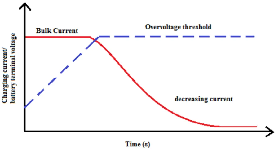
When the availability of the PV power is abundant then the load demand, then the excessive power is used to charge the battery [19-21]. While charging the battery the charging current is compared with the bulk current (Ib*), if it is not equal the signal generated by the PI controller of the BCR will go positive which in turn activates the IVR to be operated to track maximum power such that MPPT is enabled.
While MPPT is enabled, the purpose of using BCR and BVR along with the limiter is used to verify whether the battery voltage (Vb) has reached its overvoltage (Vb*) or not. In this proposed controller design for the three-port converter the battery overvoltage is chosen to be 44.7 V. If the battery voltage is not equal to the overvoltage then the bulk current (Ib*) is maintained constant which is chosen here to be 4.8 A which is termed as the constant current stage. If battery voltage is equal to the overvoltage then the bulk current decreases which are termed as the constant voltage stage as shown in Fig. 4.
As the bulk current decreases there is a limitation that it should not be decreased below the floating point value. The floating point value is given by C/100 where C is the rated capacity of the battery which is 64.61Ah. The corresponding floating point charging current value is chosen here to be 0.64 A. Therefore the bulk current has to be decreased to the floating point value, if it goes below the floating point charging current value the charging process is terminated.
B. Case: 2
b P o P PV P > +
Fig. 4. Constant current and constant voltage PV charging profile
IV.MATHEMATICAL MODEL OF PV PANEL
By considering the simplicity and the accuracy, one diode model of PV source [22]-[24] used in this work is shown in Fig. 5.
Fig. 5. Schematic of solar PV panel
The corresponding mathematical equations are as follows,
sh I D I ph I pv
I = − − (6)
(
)
{
}
n G
G pvn I n T T i K ph
I = − + (7)
[
]
{
exp(Vpv IpvRse)Vta 1}
rI D
I = + − (8)
(
)
[
Kv(T Tn) Vocn Vta]
1exp
scn I ) n T (T i K r
I
− +
− + −
= (9)
Where
ID = Current through the diode
Ish = Current through the shunt resistance Iph = Photon generated current of the PV module Ipv = PV panel current
Ki = Short-circuit current temperature Coefficient T = Temperature
Tn = Nominal Temperature (273 K) Ipvn = Nominal photocurrent of PV panel G = Insolation level (W/m2)
Gn = Nominal Insolation level (1000 W/m2) Vpv = PV panel Voltage
Vta = Thermal Voltage (=aKT/q)
Iscn = Nominal value of short circuit current Kv = open circuit voltage temperature coefficient Vocn = Nominal value of open circuit voltage
Using the equations (6) to (9), the PV model is developed in MatLab/Simulink environment and it is interfaced to the converter. To obtain the maximum required voltage (around 76 V) for this work, 5 panels are connected in series (PV array size is 5x1). The maximum power from the PV system was also tracked under different insolation by using maximum power point tracker (MPPT). Perturb and Observe algorithm is used for MPP tracking. Perturb and observe algorithm is a simple feed forward structure with less measured parameters. As per the standard test condition, the maximum power and its corresponding voltage are obtained at the temperature of 25⁰ C and for the insolation of 1000 W/m2. Table V shows the maximum power values at different insolation level.
TABLE V
Maximum Power Point Values at Different Irradiation Levels
Insolation (W/m2) Vpv (V) Isc (A)
Pmax
(W)
1000 83.5 2.55 186.3
900 82.7 2.295 166.4
800 82.2 2.04 146.4
700 81.5 1.785 126.4
600 80.6 1.53 106.5
500 80.2 1.275 86.53
400 66.7 1.02 78.5
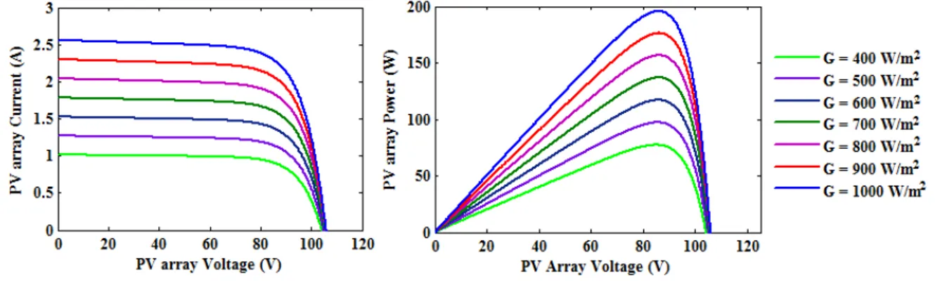
Here the ramp function of voltage represents the profile of current and power output from PV array with respect to change in voltage. The PV array current varies linearly with solar insolation and logarithmically with temperature. Fig. 6 shows the variation of characteristics of the solar PV array under different insolation varying from 1000 W/m2 to 400 W/m2 [25].
Fig. 6. Characteristics of the solar PV array for different insolation level
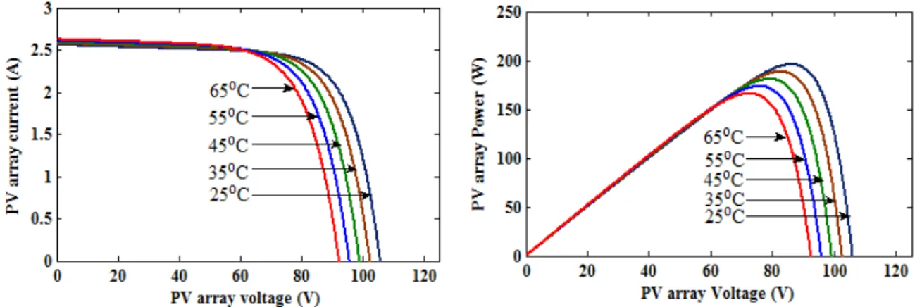
Fig. 7. Characteristics of the solar PV array for different ambient temperature level from 250C to 650C
V. RESULTS AND DISCUSSION
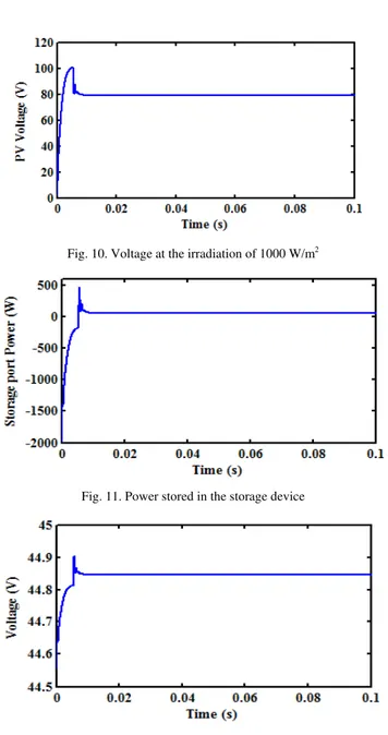
As the power balance in the system is achieved under different operating modes, Fig. 8 shows the obtained the maximum PV power of about 186.3 V at the insolation of 1000 W/m2. The corresponding PV current and the voltage of 83.5 V are also shown in Fig. 9 and Fig. 10 which is achieved by tuning the parameters of PI controller involved in the centralised controller. As the storage port is also controlled by centralised controller by the two stage controller by which over charging and over discharging is regulated. Fig. 11 shows the battery power which is around 51.89 W and the corresponding voltage of 44.85 V is shown in Fig. 12.
Fig. 8. Power supplied by the photovoltaic system at the irradiation of 1000 W/m2
Fig. 10. Voltage at the irradiation of 1000 W/m2
Fig. 11. Power stored in the storage device
Fig. 12. Storage port voltage
On the load side, the output port is controlled by means of the voltage mode controller which is also one of the parts of the centralised controller. The reference voltage is set as 42 V. The required output voltage obtained under the irradiation of 1000 W/m2 shown in Fig. 13. The corresponding output power is also shown in Fig. 14 which is around 100 W. Similarly under various irradiations the required output voltage is obtained.
Fig.14. Output power on the load side
The centralised controller is also validated by analysing the dynamic response of the three-port converter by testing the line regulation and the load regulation. The waveform shown in Fig. 15 shows the output voltage of the load port when the source port was given a transition from 1000 W/m2 to 500 W/m2 at 0.05 s. The desired output voltage of 42 V is obtained. When the irradiation lowers below the 500 W/m2 steady state error of about 1 V occurs.
Fig. 15. Dynamic response of output voltage with line regulation
The waveform shown in Fig. 16 validates the load regulation as the load on the load port changes from 18 Ω to 80 Ω and the desired output voltage of the 42 V is obtained. From Fig. 15 and Fig. 16 it was inferred that the centralised controller works good for the wide variation in the input voltage as well as for the load current.
Fig.16. Dynamic response of output voltage with load regulation
Fig. 17. Obtained ZVS of the switch S1
Fig. 18. Loss in ZVS of the switch S1
Similarly the ZVS can also be analysed for all the other switches involved in the system by varying the duty cycle or by changing the required output power.
VI.CONCLUSION
The three-port full bridge converter was analysed by interfacing PV system, storage device and the load. The power balance in the system is also achieved by means of centralised controller which is used to track maximum power PV system, safe charging and discharging on the storage device and to regulate the voltage on the output port. The dynamic response of the system was also analysed under line regulation and the load regulation. The steady state error obtained in the line regulation can be mitigated by using Fuzzy logic controller. ZVS is also analysed for the switches involved in the system.
ACKNOWLEDGEMENT
References
[1] Bryan G. Dobbs and Patrick L. Chapman, “A Multiple-input dc-dc converter topology”, IEEE Power Electronics Letters, vol. 1, no. 1, pp.6-9, March 2003
[2] Hirofumi Matsuo, Tetsuro Shigemizu, Fuji Kurokawa and Nobuya Watanabe, “Characteristics of the multiple-input dc-dc converter”, in IEEE Power Electronics Specialists Conference,1993, pp. 115- 120
[3] Yaow-Ming Chen, Yuan-Chuan Liu and Feng-Yu Wu, “Multi-input dc-dc converter based on the multiwinding transformer for renewable energy applications”, IEEE Transactions on Industry Applications, vol. 38, no. 4, pp. 1096 - 1104, July/August 2002 [4] H. Tao, A. Kotsopoulos, J.L. Duarte and M.A.M. Hendrix, “Family of multiport bidirectional dc–dc converters”, in IEE Proc. Electric
Power Application, vol. 153, no. 3, pp. 451- 458, May 2006
[5] Alexis Kwasinski, “Identification of feasible topologies for multiple-input dc–dc converters”, IEEE Transactions on Power Electronics, vol. 24, no. 3, pp. 856-861, March 2009
[6] Yuan-Chuan Liu and Yaow-Ming Chen, “A systematic approach to synthesizing multi-input dc–dc converters”, IEEE Transactions on Power Electronics, vol. 24, no. 1, pp. 856-861, Jan. 2009
[7] Alireza Khaligh, Jian Cao, and Young-Joo Lee, “A multiple-input dc–dc converter topology”, IEEE Transactions on Power Electronics, vol. 24, no. 3,pp.862 – 868, March 2009
[8] H. Tao , J.L Duarte and M.A.M. Hendrix, “Three-Port Triple-Half Bridge Bi-Directional Converter with Zero-Voltage Switching,” IEEE Transactions on Power Electronics, vol. 23, no. 2, pp. 782–792, March 2008.
[9] Haimin Tao, Andrew Kotsopoulos, Jorge L. Duarte, and M A. M. Hendrix, “Transformer-coupled multiport ZVS bidirectional dc–dc converter with wide input range”, IEEE Transactions on Power Electronics, vol. 23, no. 2, pp. 771 – 781, March 2008
[10] J. L. Duarte, Marcel Hendrix, and Marcelo Godoy Simões, “Three-port bidirectional converter for hybrid fuel cell systems”, IEEE Transactions on Power Electronics, vol. 22, no. 2, pp.480 – 487, March 2007
[11] Wei Jiang and B. Fahimi, “Multi-port power electric interface for renewable energy sources”, Applied Power Electronics Conference and Exposition, IEEE, 2009, pp. 347- 352
[12] Hongfei Wu, Runruo Chen, Junjun Zhang, Yan Xing, Haibing Hu, and Hongjuan Ge, “A Family of three-port half-bridge converters for a stand-alone renewable power system,” IEEE Transactions on Power Electronics, vol. 26, no. 9, pp. 2697-2706, Sep. 2011 [13] Hussam Al-Atrash and Issa Batarseh, “Boost-integrated phase-shift full-bridge converter for three-port interface”, Power Electronics
Specialists Conference, PESC, IEEE, 2007, pp. 2313- 2321
[14] Hongfei WuKai Sun, Runruo Chen, Haibing Hu, and Yan Xing, “Full-Bridge three-port converters with wide input voltage range for renewable power systems”, IEEE Transactions on Power Electronics, vol. 27, no. 9, pp. 3965 – 3974, Sep. 2012
[15] Zhihui Ding, Chen Yang, Zhao Zhang, Cheng Wang, and Shaojun Xie, “A Novel soft-switching multiport bidirectional dc–dc converter for hybrid energy storage system”, IEEE Transactions on Power Electronics, vol. 29, no. 4, pp. 1595 – 1609, April 2014 [16] Zhijun Qian and Hussam Al-Atrash, “Modeling and control of three-port dc-dc converter interface for satellite applications”, IEEE
Transaction on Power Electronics, vol.25, no. 3, pp. 637-649, March 2010
[17] Hussam Al-Atrash, Feng Tian, and Issa Batarseh , “Tri-Modal Half-Bridge Topology for Three-port Interface”, IEEE Transaction on Power Electronics, vol. 22, pp. 341-345, Jan. 2007.
[18] S. J. Chiang, Hsin-Jang Shieh, and Ming-Chieh Chen, “Modeling and Control of PV Charger System With SEPIC Converter”, IEEE Transactions On Industrial Electronics, vol. 56, no. 11, pp. 4344 - 4353, Nov. 2009
[19] Hongfei Wu, Peng Xu, Haibing Hu, Zihu Zhou, and Yan Xing, “Multiport converters based on integration of full-bridge and bidirectional dc–dc topologies for renewable generation systems”, IEEE Transactions On Industrial Electronics, vol. 61, no. 2, pp. 856 – 869, Feb. 2014
[20] Ankur Bhattacharjee, “Design and comparative study of three photovoltaic battery charge control algorithms in MatLab/Simulink environment” International Journal of Advanced Computer Research, vol. 2, no.3, pp. 129 – 135, Sep. 2012
[21] S. Armstrong, M.E. Glavin, and W.G. Hurley, “Comparison of battery charging algorithms for stand-alone photovoltaic systems”, IEEE, Power Electronics Specialists Conference, PESC 2008, pp. 1469-1475.
[22] R.Ramaprabha and B.L.Mathur, "MATLAB based modelling and performance study of series connected SPV a under partial shaded conditions," Journal of Sustainable Development, vo1. 2, vo.3, pp. 85-94, Nov 2009
[23] Huan-Liang Tsai et.al, “Development of generalized photovoltaic model using matlab/simulink”, in Proc. World Congress on Engineering and Computer Science, WCECS 2008, San Francisco, USA, pp. 22 – 24.
[24] J.A. Ramos Hernanz, Campayo Martín, J.J. Zamora Belver, J. Larrañaga Lesaka, E. Zulueta Guerrero, and E. Puelles Pérez, “Modelling of Photovoltaic Module”, in Proc. International Conference on Renewable Energies and Power Quality ICREPQ‘10, Granada(Spain), March 2010
[25] Wang nian chun, Wu MeiYue, and Shi GuoSheng, “Study on characteristics of photovoltaic cells based on matlab simulation”, Power and Energy Engineering Conference (APPEEC), Asia-Pacific IEEE , 2011, pp. 1- 4.
[26] Nicola Famia, Giovanni Petrone, Giovanni Spagnuolo, and Massimo Vitelli, “Optimization of perturb and observe maximum power point tracking method”, IEEE Transaction on Power Electronics, vol.20, no. 4, pp. 963 – 973, July 2005.