ISSN 2277-1956/V1N3-1748-1756
Improved Multispanning Tree Routing Using Efficient
and Reliable Routing Algorithm for Irregular
Networks
L. Keerthana 1, K. P. Sampoornam 2
1PG Scholar, Department of ECE, K.S.R. College of Engg. , Tiruchengode, Tamil Nadu, 637215, India.
2Associate Professor, Department of ECE, K.S.R. College of Engg. , Tiruchengode, Tamil Nadu, 637215, India.
Abstract-A Strategy of Multispanning Tree Zone Ordered Label Based routing is improved with Efficient and Reliable (EAR) routing for irregular networks is presented and analyzed in this work. Most existing deadlock free routing methods for irregular topologies impose several limitations on node and channel labeling in an irregular network is based on a pre-defined spanning tree.It is not possible to form a deadlock free zone of three or four channel labels for two spanning tree. So this existing Multispanning Tree Zone Ordered Label Based routing is modified with Efficient and Reliable (EAR) routing. EAR is based on four parameters length of the path,distance traversed,transmission of link and energy levels to dynamically determine and maintain the best routes.. The simulation results have shown highest packet delivery ratio, minimum latency, and energy consumption.
Key words:routing, irregular networks, energy efficiency, reliable routing
1. Introduction
A WSN typically consists of a large number of low-cost, low-power, and multifunctional wireless sensor nodes, with sensing, wireless communications and computation capabilities. These sensor nodes communicate over short distance via a wireless medium and collaborate to accomplish a common task, for example, environment monitoring, military surveillance, and industrial process control. The basic philosophy behind WSNs is that, while the capability of each individual sensor node is limited, the aggregate power of the entire network is sufficient for the required mission. In many WSN applications the deployment of sensor nodes is performed in an ad hoc fashion without careful planning and engineering. Once deployed the sensor nodes must be able to autonomously organize themselves into a wireless communication network. Sensor nodes are battery-powered and are expected to operate without attendance for a relatively long period of time. In most cases it is very difficult and even impossible to change or recharge batteries for the sensor nodes.
WSNs are characterized with denser levels of sensor node deployment, higher unreliability of sensor nodes, and sever power, computation, and memory constraints. Thus the unique characteristics and constraints present many new challenges for the development and application of WSNs. Routing in WSN can be divided in to flat-based routing,hierarchical based routing and location-based routing depending on network structure. In flat-based routing all nodes are typically assigned equal nodes(or) functionality. In hierarchical-based routing nodes were play different routing roles in the network. It is well known technique with special advantage of scalability and efficiency.
International Journal of Electronics and Computer Science Engineering
Available Online at www.ijecse.org ISSN- 2277-1956
ISSN 2277-1956/V1N3-1748-1756
communication range of neighboring nodes. The fault tolerance of a protocol is replaced by an alternate path exists between a source and a destination when the primary path fails. This can be increased by maintaining multiple path between the source and the destination at the expenses of increased energy. The alternate paths are kept alive by sending periodic message.
Deadlocks can happen without having a carefully designed routing scheme. Avoiding deadlocks when designing routing algorithms for irregular networks require more sophisticated mechanisms as a result of the irregularity in the network topology. In this paper the deadlock is removed by using Efficient and Reliable(EAR) routing algorithm.
2. Related Work
Several routing algorithm have been used this multispanning Tree and EAR routing such as Up/Down routing [12],Prefix routing [14], Left/Right routing [8], L-turn routing [8], Layered routing [9], The source of Deadlock among the packet is a cyclic dependency between the busy and requested communication channels [15]. To incorpate new links and to bypass links and switches a distributed algorithm is used in switch processors [10]. A popular switching technique in direct networks is wormhole routing in wormhole routing a message gets switched along a network by first dividing the message into packets and the packets into flow control digits or flits [5], in K-ary n-cubes deadlock avoidance scheme it requires exponential number of virtual channels but in planar adaptive routing it requires only a constant number of virtual channel [5]. In Gradient Broadcast (GRAB ) routing is based on cost and credit. As it floods packet the energy consumption is high [16]. Adhoc On-Demand Vector routing (AODV) the pointer is carried to the full route by the data packet which takes additional energy overheads [3]. In Gradient Based routing (GBR) all messages will flow in the direction of the greatest gradient [14]. To attain the global minimum energy of the entire network at each node a local optimization procedure is executed and it guarantees strong connectivity [11]. Frequent changes in the topology of sensor networks [1]. To reduce the measurement overhead Bayesian inference is used [6]. The total energy consumption of the proactive and the reactive networks taking in to account of transmitting, listening, and sleeping energy [18]. A physical layer driven approach to protocol and algorithm design for wireless sensor networks in order to meet the system lifetime goals of wireless sensor applications [17]
3. Multispanning Tree Zone Ordered Label Based Routing
• In this existing multispanning tree the routing is carried out using labeling techniques, zone concept and ordering of zones
• There is no cyclic dependency between channels of the same label in the labeling scheme that uses one
spanning tree
• It is not possible to form deadlock-free zones of three or four channel labels for two spanning trees.
• So this multispanning tree is modified with Efficient and Reliable routing algorithm in order to remove the
deadlock and packet latency
3.1. Labeling Techniques
Routing is based on labeling the nodes and channels.Spanning tree construction is mainly used for labeling the network.Some of the routing are using this labeling method they are l-turn routing[5], Up*/down* [12], prefix [14], left/ right [5],
ISSN 2277-1956/V1N3-1748-1756
label is prefix of the label of the destination node. The important point to be considered is there is no cyclic dependency in the labels.
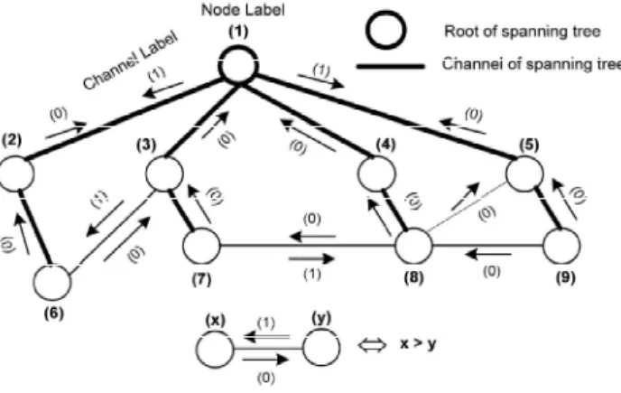
The arbitrary node is considered as a root node of the spanning tree. While constructing the spanning tree the nodes are labeled. Root node is labeled “1” and the node after visiting the root node is labeled “2”and so on. The node labeling continues in a increasing manner.The node facing the lower node is labeled as “0” and node goes away from lower node is labeled as “1”. Different spanning treeis constructed when the spanning tree construction repeats several times. In each construction the spanning tree should be different for this from the root node the spanning tree construction should start.
Fig. 1. Correct and incorrect ways of channel labeling in four-ring network.
Breaking of existing cyclic dependency between channels of a simple four -ring network. In Fig. 1(a) Graph is not labeled well there is a cyclic dependency between the channel labels. Fig. 1(b) and 1(c) two and three labeling is used. In fig 2c there is no cyclic dependency between the channel of same labels.
3.2. Zone concept
In some cases the channel with different labels have no cyclic dependency. In l-turn routing channels are assigned four differentlabels, namely, up-left (UL), up-right (UR), down-left (DL), and down-right (DR). In it is proved that channels with labels UR and DR do not have cyclic dependency. So messages can use them without any restrictions. messages can use either UR channels after traversing DR channels or vice versa.
(UR) → (DR) →(UR) → (UR)
Cyclic independent channels is used by arbitrary message adaptively even if they have different labels, cyclic independent channel labels in to a group. Such group of channel labels are called zones. They are cyclic independent Cyclic dependency is a situation in which a message is holding a channel, while requesting another channel being used by another message.Consider a set of messages such that every message in the set has reserved a channel and requests a channel held by another message in the set. Obviously, that channel cannot be granted, and that situation will last forever. The situation is called cyclic dependency.
3.3. Ordering the Zones
In XY routing the two deadlock free zones of x and y. X→Y
There is a predefinied ordering in all label based routing for travelling between zones. The channel of the previous travesed zones cannot be used by a message. However the same zone channels can be used by a message.
Routing have two main properties they are deadlock freedom and connectivity.
CONNECTIVITY
By ordering the zone in a proper way then the zone ordering guarantees connectivity. Zone orders are not the same in different routing. In dimension order routing any order of zone provides a connected routing. In up*/down*
International Journal of Electronics and Computer Science Engineering
Available Online at www.ijecse.org ISSN- 2277-1956
ISSN 2277-1956/V1N3-1748-1756
DEADLOCK FREEDOMThe same zone channels should not be cyclic dependent. This gives the deadlock freedom in intrazone routing. The predefined zone ordering assures deadlock freedom in interzone routing algorithm.
3.4. Spanning Tree Construction
The message can reach the destination by traversing either “0” channel or “1” channel according to the node position.
• “0” channels-The sourcenode is the ancestor of the destination.
• “1” channels-the source node is a descendent of the destination.
• ‘0’ and ‘1’ channels-the source node is neither the ancestor nor thedescendent of the destination,the
message gets to the nearest ancestor of the destination by traversing“0” channels, and then, reaches the destination using“1” channels.
Fig. 2. Spanning tree construction and the associated node and channel labeling
Up channel: A channel in the spanning tree that directs towards the root
Down channel: A channel in the spanning tree that directs away from the root
Cross channel: A channel that is not ins the spanning tree, but it connects two nodes at different branches of the tree
Shortcut: A channel that is not in the spanning tree,but it connects two nodes in the same branch of the tree(Such a channel occur only in a non-minimum spanning tree)
Up-shortcut: a shortcut that directs towards the root
Down_shortcut: A shortcut directs away from the root
4444.... Design oDesign oDesign of EARDesign of EARf EARf EAR
The procedural design of EAR may be divided into four phases: Initialization phase, Linkscore metric phase, data forwarding phase and route update. Theseare detailed in the following sections.
4.1. Initialization Phase
ISSN 2277-1956/V1N3-1748-1756
faster propagation of routes and sa packet before they begin their initia hop node’s ID is used to index a rou keeps only one route entry for a neig4.2. Linkscore metric Phase
The shortest route is considered as b on the hop-count the shortest routes RPT packet flows through these link table may be re-admitted again LinkS of the next hop node (0.0 to 100.0), 100.0) and WT – assigned weight fo sum must equal 1. For example, in
this scenario, WE = 0.7 and WT
conservation in path selection. Conv giving higher emphasis to the select taken for Linkscoreand higher value is initially assigned to PT. When su drops as a node consumes its energy
Fig. Linkscore is used when there a admitted in routing table. Link repl this targets the replacement of lowes to be placed when there is more than the shorter route is compared agains length. Since the routing table maint a given time. The size scales slowly one entry to the next hop node.
4.3. Data Forwarding Phase
A RPT packets are generated at a pe header fields and information of inte to traverse before it reaches the hub
56
saving of control packets is enabled when a portion o tialization process more than one route to the hub can b route in the routing table. Even though neighbor nodes h eighbor node. Only the best route is stored in routing tab
s best route with the lowestlatency and consumes the le tes are admitted less desirable link will start exhibiting h inks and omitted fromthe routing table again a period of nkScore is defined as LinkScore= (PE × WE +PT × WT 0), WE– assigned weight for PE (0.0 to 1.0), PT – transm forPT (0.0 to 1.0). Weights, WE and WT , may be deter in a lownoise environment, the probability of successfu
T = 0.3may be chosen allowing routing decisions
nversely, in anoisy environment, WT = 0.7 and WE = 0 ection of highreliability paths over energy conservation lue indicates the better link. The unknown link performa
subsequent packet transmissions succeed the PT value gy resources.
Fig. 3. Illustration of forwarding based on Linkscore metric e are two links of different routes with the same hub
placement is initiated when routing table is full and wh est Linkscore value and ignores the backlisted links. Th han one entry with the same Linkscore. In the routing ta inst with the worst route. The highest Linkscore is admit
intains the best available link the packets travel in best r wly with the network size and multiple hubs since the r
periodic intervals or sleep by sensor nodes waiting for s nterest is present in an RPT packet: ExpPathLen and Nu ub is given in first field. It is defined asExpPathLen= NH
n of nodes receives a RREP n be stored in the node. Next s have multiple routes a node table for each route entry.
least energy. In EAR, based g high packet loss rate when of time these omitted routing T ), where PE – energy level nsmissionsuccess rate (0.0 to terminedempirically but their sful transmissionis higher. In ns to focus moreon energy 0.3 could bechosen instead, on. From 0 to 100 values are mance and an arbitrary value ue rises. PE starts at 100 and
ub distance competing to be when a new link is received The longest length is chosen table the incoming route and itted if there is a tie in route st route from node to a hub at e routing table contains only
International Journal of Electronics and Computer Science Engineering
Available Online at www.ijecse.org ISSN- 2277-1956
ISSN 2277-1956/V1N3-1748-1756
The number of hops from this node to the hub for a route selected is NH. The selected route need not to be the
shortest route but ExpPathLenis bounded by the network diameter. The assigned weight nα such that 0.0 < α≤ 1.0.
The minimum number of hops to such the hub is atleast 1. The distance of a packet has traversed is NumHopTraversed and is initialized as 0 to the next node the packet is forwarded in the route. NumHopTraversed is incremented by one when the next node receives the packet and compare it with ExpPathLen. Rather than just the shortest route may favor a route with better performing links by α>>0.0. There must be changes in network topology if the number of hops that a packet has traversed exceeds the expected number. During this period of instability the shortest route to the hub is taken by the packet. BufUtilLvlis used at each node to prevent the potential deadlocks This BufUtilLvlis used to store the current utilization level of the packet output buffer. BLThreshold gives a threshold value. Where BLThreshold<Bmax (max size of buffer). The packet will be relayed on the shortest route to the is BufUtilLvl greater than BLThreshold. The buffer is almost full and there will be always be atleast one buffer space for transit packet to be routed the new packets will not be injected. This is ensures by buffer control mechanism.
Proposition 1: EAR is deadlock-free in a connected wireless sensor network.
Proof: We recall that ExpPathLen= NH × α. Let h be the number of hops traversed by a packet.
Case 1: ExpPathLen≤ h: The shortest route in the routing table is selected for forwarding by data dissemination algorithm. The highest LinkScore is selected if there is a tie. At every intermediate node the shortest route is selected this will lead the packet to a hub and no node is revisited.
Case 2: ExpPathLen> h: For forwarding the highest LinkScore in the routing table is selected by data dissemination algorithm. The shortest route is chosen if there is a tie in Linkscore. As a sender node highest LinkScore valued neighboring node may have the same hop count to the hub this results the packet being re-transmitted to the sender.
Temporary loop may possible. Since BLThreshold<Bmax is used a deadlock can never happen and the buffer will
never be full.
If the packet output buffer exceeds BLThreshold a packet will be forwarded on the shortest route this breaking the loop. NH+D gives the distance of a packet travels before reaching a hub. When the distance of the furthest node from a hub in terms of hop is given as D. Node A generated a packet when α is set to 1 ExpPathLen= NH. The
packet is forwarded to its neighbor node B which has the highest Linkscore when ExpPathLen>NumHopTraversed. To the furthest node from a hub the packet will have been routed the packet will need a maximum of D hops to reach a hub. When the packet is forwarded on the shortest route D is the distance of the furthest node from a hub in hops. EAR is livelock free.
4.4. Route Update.
“Best” routes are updated in the routing table continuously by the sensor nodes. Instead of explicit control packets the handshaking mechanism at the MAC layer is used by the EAR. RTS and CTS packets are piggypacked on route information processed. Instead of separate DATA-ACK utilizing RTS-CTS handshaking result in more current route
information for a node. S-MAC (Sensor MAC) is used by EAR this S-MAC has Overhearing Avoidanceis one of
ISSN 2277-1956/V1N3-1748-1756
information getting exchange periodically between nodes is costly in terms of energy consumption and bandwidth usage.
5. Simulation Results
Packet delivery ratio (PDR): measures the percentage of data packets generated by nodes that are successfully delivered expressed as
x100%
Packet latency: measures the average time it takes to route a data packet from the source node to the hub. It is expressed as
∑ !" " # $% &'"(%) !" * " "(" Energy Consumption: This measures the energy expended per delivered data packet
∑ + "(,#"- " " '#" ℎ % " $% &'"(%) !" * " "("
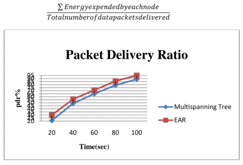
Fig. 4. Packet Delivery Ratio For Mulatispanning and EAR.
Fig.4 shows the Packet Delivery Ratio. In EAR routing is based on energy levels, distance traversed of the nodes. It will not flood the packets. The poor performance links are discards from the routing table. EAR achived the highest PDR.
20 25 30 35 40 45 50 55 60 65 70 75 80 85 90 95
20 40 60 80 100
p
d
r%
Time(sec)
Packet Delivery Ratio
Multispanning Tree
International Journal of Electronics and Computer Science Engineering
Available Online at www.ijecse.org ISSN- 2277-1956
ISSN 2277-1956/V1N3-1748-1756
Fig. 5. Packet Latency for Multispanning Tree and EAR.
Fig.5 shows the Packet latency comparisons for multispanning tree and EAR. In EAR the latency is minimum because it is deadlock free and it having lower control overhead.
Fig.6. Energy Consumption for Multispanning Tree and EAR.
Fig.6 shows the energy consumption comparisions for Multispanning Tree and EAR. In this compared to all
other routing algorithms EAR having the minimum energy consumption.With minimal compramises of energy EAR gives the better performance.
Route discovery in AODV is energy intensive. GRAB having high level of energy consumption as it is floods packets. DSR can lead to significant energy consumption specialy in larger networks. The EAR and GBR are slightly competitive. The slight improvement over GBR is the EAR dynamically accounting for variable link
0.98 0.99 1 1.01 1.02 1.03 1.04 1.05 1.06 1.07 1.08 1.09
40 60 80 100 120
L
a
te
n
cy
(m
s)
time(sec)
Packet Latency
Multispanning Tree
EAR
0 50 100 150 200 250 300
0 50 100 150 200 250 300
E
n
er
g
y
(j
o
u
le
)
No of nodes
Energy Consumption
Multispanning Tree
ISSN 2277-1956/V1N3-1748-1756
performance and forwarding packets only on “best” routes by piggypacking on RTS/CTS packets. Current route information is disseminated quickly with low energy costs.
6. Conclusion
In multispanning tree zone-ordered label-based routing the deadlock will occur if three or four channel labels for two spanning tree. Here this multispanning tree routing is modified with efficient and reliable(EAR) routing. This routing algorithm is not restricted for irregular networks In EAR routes are managed based on length of the path and a weighted combinationof distance traveled, energy level and RF link performancehistory. Compared to existing routing protocols this simulation results performs good in terms of packetdelivery ratio, scalability and energy consumption even in high network traffic and the packet latency is minimum. In future it can also implemented in dynamic networks also. The routing algorithm is efficient and reliable.
References
[1] Akyildiz.I.F, Cayirci.E, Sankarasubramaniam.Y, and Su.W, “A survey on sensor networks," IEEE Trans. Commun., pp. 102-114, 2002.
[2] Bokareva.T, Bulusu.N, and Jha.S, “A performance comparison of data dissemination protocols for wireless sensor networks," in Proc. IEEEGlobecom, 2004, pp. 85-89.
[3] Das.S.R, Perkins.C.E, and Royer.E.M, “Ad hoc on-demand distance vector (AODV) routing," IETF Internet draft, draft-ietf-manet-aodv-13.txt, Feb. 2003 (work in progress).
[4] Estrin.D, Girod.L, Pottie.G, and Srivastava.M, “Instrumenting the world with wireless sensor networks," in Proc. International Conf. Acoustics, Speech Signal Processing (ICASSP), May 2001, pp. 1-4.
[5] Glass.C.J and Ni.L.M, “The Turn Model for Adaptive Routing,” Proc. Int’l Conf. Computer Architecture., pp. 278-287, 1992. [6] Goldsmith.A and Chua.S, “Variable-rate variable-power M-QAM for fading channels," IEEE Trans. Commun., vol. 45, pp.
1218-1230, Oct.1997.
[7] Kahn.J.M, Katz.R.H, and Pister.K.S.J, “Next century challenges: mobile networking for smart dust," in Proc. 5th Annual ACM/IEEE International Conf. Mobile Computing Networking, 1999, pp. 271-278.
[8] Koibuchi.M, Funahashi.A, Jouraku.A, and Amano.H, “L-Turn Routing: An Adaptive Routing in Irregular Networks,” Proc. Int’l Parallel Processing Conf., pp. 383-392, 2001.
[9] Lysne.O, Skeie.T, Reinemo.S, and Theiss.I, “Layered Routing in Irregular Networks,” IEEE Trans. Parallel and Distributed Systems, vol. 17, no. 1, pp. 51-65, Jan. 2006.
[10] Puente.V, Gregorio.J.A, Vallejo.F, Beivide.R, and Izu.C, “High- Performance Adaptive Routing for Networks with Arbitrary Topology,” J. System Architecture, vol. 52, pp. 345-358, 2006.
[11] Rodoplu.V and Meng.T.H, “Minimum energy mobile wireless net- works," IEEE J. Select. Areas Commun., vol. 17, no. 8, pp. 1333-1344,Aug. 1999..
[12] Sancho.J.C, Robles.A, and Duato.J, “An Effective Methodology to Improve the Performance of the Up*/Down* Routing Algorithm,” IEEE Trans. Parallel and Distributed Systems, vol. 15, no. 8, pp. 740-745, Aug. 2004.
[13] Schroeder.M.T (et. al)., “Autonet: A High-Speed, Self Configuring Local Area Network Using Point-to-Point Links,” J. Selected Areas in Comm., vol. 9, pp. 1318-1335, 1991.
[14] Schurgers.C, Raghunathan.V, and Srivastava.M.B, “Power manage-ment for energy-aware communication systems," ACM Trans. EmbeddedComputing Systems, vol. 2, no. 3, pp. 431-447, Aug. 2003.
[15] Wu.J and Sheng.L, “Deadlock-Free Routing in IrregularNetworks Using Prefix Routing,” DIMACS Technical Report 99- 19, 1999. [16] Ye.F, Zhong.G, Lu.S, and Zhang.L, “Gradient broadcast: a robust data delivery protocol for large scale sensor networks,"
ACM Wireless Networks, vol. 11, no. 2, pp. 285-298, 2005
[17] Zhao.Q and Tong.L, “Energy efficiency of large-scale wireless net- works: proactive versus reactive," IEEE J. Select. Areas Commun., vol.23, no. 5, pp. 1100-1112, 2005.