Journal of Computer Science 2 (2): 201-204, 2006 ISSN 1549-3636
© 2006 Science Publications
Corresponding Author: Rachid Boudour, Department of Computer Science, University of Annaba, Bp. 12, Annaba, Algeria Tel / Fax: 213-38-87-24-36
201
From Design Specification to SystemC
Rachid Boudour and Mohamed T. Kimour
Department of Computer Science, University of Annaba, Bp. 12, Annaba, Algeria
Abstract: In this paper, we present a framework for transforming the design model into SystemC code. Such a framework uses as input UML state machine and object diagrams, which are more and more used as design models in embedded systems. To do this, we have firstly used Poseidon tool for editing the design model and generating the XMI representation, and secondly integrated a transformation module leading to SystemC code. The mapping to SystemC code offers not only a system-level executable specification, but also a means to facilitating the system partitioning in hardware and software parts.
Keywords UML 2.0, SystemC, MDA, XMI, Codesign, Embedded Systems
INTRODUCTION
Embedded systems are currently used in the most diverse contexts from automobiles and aeronautics to home appliances, medical equipment, multimedia and communication devices [1,2,3]. Such systems are typically characterized by their dedicated function, real-time behavior, and high requirements on reliability and correctness. The interest in formal methods aiming at verifying embedded systems has increased recently due to the important role of correctness in such systems.
Embedded systems development requires more and more severe requirements such as, product quality, security, and time-to-market. They are more and more complex and a great number of functionalities are to be conceived [4]. However, nowadays, designers have a few tools to help them in satisfying these requirements. In embedded systems, different tasks are generally defined and distributed to different computers, requiring specific languages to describe their functionalities. Recently, SystemC [5] has been introduced as a language that offers description mechanisms for both hardware and software parts.
Typically, a development process in embedded systems according to MDA approach [6] firstly defines PIM models which are transformed to PSM models using appropriate mapping rules (Fig. 1). On the other hand, UML artifacts [7] are widely used in most existing MDA based development processes for embedded systems [8,9,10]. UML State machines and object diagrams are usually used as design model artifacts.
In this paper, we present a transformation process for the two UML models that, from a design specification (PIM), generate a corresponding SystemC code, after using Poseidon UML tool [8]. Precisely, we have added some extensions to the models in order to obtain a precise transformation leading to a SystemC as en executable model.
The rest of the paper organized as follows: section 2 presents the uses of UML in embedded system modeling as well as the MDA approach in that area. Section 3 is concerned with our transformation process. Finally, we conclude our work and give some perspectives in section 4.
EMBEDDED SOFTWARE DEVELOPMENT PROCESS
Generally, embedded system development is performed according to different variants and concerns a specific application or project. Recently, MDA and UML are being more and more used in this area. MDA
MDA is a software development framework where models are the artifacts of the first class, having as main objectives the automatic code generation. The main purpose of this approach is consequently, to reduce the gap between system-level models and the code [10]. MDA is based on the definition of platform independent models (PIM) using high-level specification language, especially UML.
Fig.1: MDA architecture
The objective is to obtain sufficiently precise models leading to automatic code generation. Such a code depends, naturally, on the platform and exhibits a sound synchronization with the PIM models [10]. Furthermore, direct model transformation into the code
PIM
PSM
J. Computer Sci., 2 (2): 201-204, 2006
202 facilitates the iterative and incremental development, which is a fundamental principle of RUP process [11]. Essentially, MDA is based on UML, MOF and XMI technologies.
UML
Initially, proposed as a unified notation for OO software, UML is the main models used in MDA. Semantics of UML diagrams allow designers for defining platform independent description. Various UML tools are available such as IBM’s Rational Toolset [11], Poseidon [9], and I-Logix’s Rhapsody [12]. Models interchange between these tools is allowed thanks to XMI standard [13]. XMI is based on XML representation to describe UML diagrams, which are comprehensible by the machine. Most of UML tools can automatically generate XMI representation we use in this work as a basis of our model transformation approach. Furthermore, UML is associated with a semantic which is based on Time Petri nets [14], leading to an executable model centered on the object concurrent actions. This property may be integrated in a distributed execution.
pressButton
requestUpdate
cabMoving cabineSelection
requestHandling
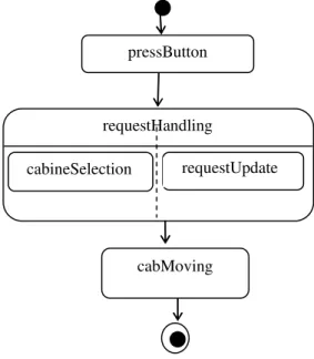
Fig. 2: Example of SystemC
On the other hand, an object oriented system is composed of a set of related objects. UML allows to represent such system according different views expressed with diagrams. Those diagrams allow to represent both structural aspects (classes, objects, relationships) and behavioral aspects.
Among these different views, statecharts (Fig. 2) allow to illustrate the object behavior according to the interactions exhibited between the system components.
This diagram is composed of nodes and edges. The former represents states and the latter represents transitions. This automaton type may be associated with a class in order to model the instances behavior.
Such instances may be considered as active objects. An automaton may also be used to specify the class protocol. It therefore describes the rules that govern the object utilization and the behaviour an object set.
The use of action semantics of UML constitutes a decisive step upon the widely use of MDA. This allows to not only precisely building the models but also to verify and test them before code generation [15].
SystemC
SystemC has a notion of container class, called module. A module can be instantiated within other modules, enabling structural design hierarchies to be built. It provides the ability to encapsulate structure and functionality of both hardware and software parts for partitioning a design of a system. Each module may contain variables as simple data members, ports for communication with the outside environment and processes for performing modules’ functionality and expressing concurrency in the system. Commonly used data types include single bits, bit vectors, characters, integers, floating point numbers, vectors of integers, etc.
SystemC is an open standard controlled by an international steering group involved in the Electronic Design Automation (EDA) consortium. It is one of the most promising system-level design languages that support the description and validation of complex systems in an environment based on C++ analysis techniques have been introduced to overcome this problem.
Concurrent behaviors are modeled using processes. The simple SystemC example (Fig. 3) consists of a module with two processes. The system starts by passing on the control to the module where computation is done every tenth cycles. A process can be thought of as an independent thread of control which resumes execution when some set of events occur or some signals change.
Process 1 Process 2
init
while(true) { for i=0,10 {
wait(e1) F4(); port1.write e2.notify } }
init
while(true) { for i=0,10 {
F1(); e1.notify; F2();
wait until(e2,3); …=port1.read; F3();
} }
Fig. 3: Example of SystemC Module with two Processes
J. Computer Sci., 2 (2): 201-204, 2006
203 Since processes execute concurrently and may suspend and resume execution at user-specified points, SystemC process instances generally require their own independent execution stack. (An equivalent situation in the software world arises in multi-threaded applications—each thread requires its own execution stack).
To model communication and synchronization between the processes, SystemC provides mechanisms of ports, channels, interfaces and events. A port of a module is a proxy object through which the process accesses to a channel interface. The interface defines the set of access functions (methods) for a channel.
The channel is an object that provides the implementation of these functions to serve as container to encapsulate the communication and synchronization of blocks. Channels implement one or more interfaces. There are two kinds of channels: primitive channels and hierarchical channels. Primitive channels do not exhibit any visible structure, do not contain processes, and cannot directly access other primitive channels.
A hierarchical channel is a module, i.e., it can have structure and can contain processes. It also can directly access other channels. An event is a flexible, low-level synchronization primitive that is used to construct other forms of synchronization.
Unlike signals, an event does not have a type and does not transmit a value. Events only transfer control from one thread of execution to another. Also, an event notification always causes sensitive processes to be resumed, while an assignment to a signal only causes sensitive processes to be resumed if the new signal value is different from the previous value.
Since processes execute concurrently and may suspend and resume execution at user-specified points, SystemC process instances generally require their own independent execution stack. (An equivalent situation in the software world arises in multi-threaded applications—each thread requires its own execution stack).
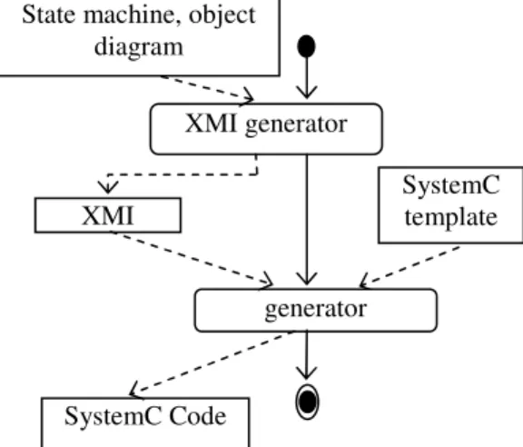
Fig. 4: SystemC code generation process.
FROM UML TO SYSTEMC
Our objective is to allow building reliable software by assembling and integrating components while validating and evaluating functional and non-functional requirements. In this context, the engineering process defines mainly analysis phases and specification. Indeed, today’s, software development processes are model-driven. MDA (Model Driven Architecture) prescribes separation of concerns, that is, models are transformed from PIM step (Platform Independent Model) to the PSM one (Platform Specific Model) in order to lead to an executable code automatically obtained from that models. Therefore, we are considering a transformation process in the software life cycle.
Different model transformation engines exist and are used in various software development process, however, the presents some drawbacks in the code generation components.
Our approach starts from the UML model in particular, the statechart diagram and the object diagram, to derive automatically a systemC source code Our transformation approach uses as input state machine and object diagrams. To facilitate the transformation process, we have defined an intermediate representation for the resulted XMI model of the design that it is introduced using Poseidon. Transformation steps
Fig. 4 illustrates our transformation process. It depicts the following steps:
a) The state machine diagram is edited using Poseidon, which allows generating the corresponding XMI file.
b) XMI uses an XML predefined attributes and elements to specify states, events and actions.
c) XMI file is used to build a dependency state matrix. The row contains the following attributes: <st_sink, st_target, evt, guard, action> that model a dependency between two states, where dependency, st_sink and st_target represent respectively the sink state number and the target state number.
d) Using the obtained matrix and a specific SystemC template we generate the corresponding SystemC code by applying the appropriate mapping rules.
CONCLUSION
In this paper, we have given a transformational approach from a design model expressed in UML to SystemC in the area of embedded systems. The approach used as input two UML diagrams, that is, statecharts and object diagram, and produces a systemC source code. Also, an intermediate representation is defined in order to facilitate the transformation process and verify its correctness. Such transformation has State machine, object
diagram
XMI
XMI generator
generator
SystemC Code
J. Computer Sci., 2 (2): 201-204, 2006
204 many practical implications, such as automatic code generation and better quality system.
Currently, we are in the process of implementing a tool support, and we plan to complete our approach to deal with other important UML diagrams especially the sequence diagram in order to automatically generate test cases.
REFERENCES
1. Gomaa H. 2000. Designing Concurrent, Distributed, and Real-Time Applications with UML. Addison-Wesley.
2. Graaf B., Lormans M., Toetenel H.. 2003. Embedded Software Engineering: the State of the Practice. IEEE Software, pp. 61-69.
3. Hsiung P.-A 1999. Hardware-Software Coverification of Concurrent Embedded Real-Time Systems. in Proc. Euromicro RTS, pp. 216-223. 4. Douglass B. P. 2000. Real-Time UML: Developing
Efficient Objects for Embedded Systems. Object Technology, Addison-Wesley, 2nd edition.
5. Groetker T., Liao S., Martin G., Swan S.. 2002. System Design with SystemC. Kluwer Academic Publishers.
6. MDA: OMG. 2006. Model-Driven Architecture, www.omg.org/mda,.
7. UML™ 2, OMG. 2003. UML™ 2.0 Superstructure. Final Adopted Specification, www.omg.org/technology/documents/modeling_ 8. GentleWare.. 2004. .Poseidon for UML.
www.gentleware.com/products,
9. J. Warmer and A. Kleppe. 2003. The Object Constraint Language, Second Edition: Getting Your Models Ready for MDA.: Addison-Wesley. 10. D. Frankel. 2003. .Model Driven Architecture:
Applying MDA to Enterprise Computing: OMG Press.
11. Rational-IBM. 2006.
www-306.ibm.com/software/rational.
12. Ilogix. 2006. www.ilogix.com/rhapsody/rhaps. 13. OMG. 2006. www.omg.org/technology/xml.. 14. Peterson J. L. 1981. Petri Net Theory and the
Modeling of Systems. Englewood Cliffs: Prentice Hall.
15. Jerraya A.and Wolf W. 2005.