METRIC SURVEY OF THE MONUMENT OF QUEEN ELISENDA'S TOMB IN THE
MONASTERY OF PEDRALBES, BARCELONA
Mª. A. Núñeza, *, F. Buill a, J. Regot b, A. Mesa b
a
Dept. Ingeniería del Terreno, Cartográfica y Geofísica, UPC, Dr. Marañón 44-50, 08028 Barcelona (Spain) -
m.amparo.nunez@upc.edu, felipe.buil@upc.edu
b
Dept. Expresión Gráfica Arquitectónica I. UPC, Diagonal 649, 08028 Barcelona (Spain) - joaquim.regot@upc.edu,
andres.de.mesa@upc.edu
Commission V, WG 4
KEY WORDS: Cultural Heritage, Digital Photogrammetry, Laser Scanning, Modelling.
ABSTRACT:
When an urban development is planned the cartography of this territory is necessary, in the same way before starting a project to rehabilitate a monument the graphic information about it has to be available.
At present, different techniques are available which allow to obtain three-dimensional models with a different accuracy level and runtimes.
This paper shows the work carried out to obtain the graphic information and three-dimensional models that are necessary for the rehabilitation project of the tomb of Queen Elisenda in the Monastery of Pedralbes, Barcelona (Spain). This monument has the peculiarity of being symmetrical about the wall separating monastery church and the cloister. To do this, different techniques have been used that allow us to obtain an accurate model and as complete as possible, for the analysis of the construction process of the monument.
In order to achieve the complete architectural survey the integration of laser scanning and photogrammetric data, and CAD models has been necessary. Due to the detail of the sculptures and the Queen’s sarcophagus two sensors, with different resolution, range and accuracy, have been used to obtain the laser scanning data. Stereo pairs have been taken to obtain the 3D model of these elements to complete the model and obtain an ortophotography.
In this way, a comparative analysis of both techniques has been carried out, in order to decide which one is the suitable for certain application. This investigation has been restricted to the tomb, in the two symmetrical parts of the monument.
* Corresponding author.
1. INTRODUCTION
Nowadays there are several techniques that allow to obtain the precise documentation of cultural heritage elements. This information is essential to carry out the necessary studies and projects of renovation and restoration.
Among these techniques the most widely used are digital photogrammetry and laser scanning, in most of the cases with a topographic support. Several authors (Agnello and Lo Brutto, 2007; Demir at al., 2004; Lambers et al., 2007; Yastikli, 2007) show the integration of both methods like one solution, at the present time, to collect the three-dimensional information necessary in the cultural heritage documentation.
These methods have advantages and drawbacks (Demir et al., 2004) but both of them have the same problem regards the occlusions, geometric accuracy, size of the models obtained (that make difficult their management), characteristic lines extraction,....
Close Range Stereophotogrammetry has been extensively used for obtaining 3D models of elements from photographs (Remondino and El-Hakim, 2006; Yilmaz et al., 2007), since it allow to collect geometrical data as well as texture information. In same cases, which the cultural heritage object surface is
considered a plane in, a digital image rectification is enough to obtain the metric documentation. But when we work with complex object it is necessary the stereophotogrammetry that allows 3D vectorization and digital surface model generation with a semi-automatic or automatic process (Yastikli, 2007) based on image correlation (Schenk, 1999). One of the products of this process is the ortophotography, obtained after removing the effects of lens distortions, tilt and relief displacement with the help of the digital surface model.
As alternative or complement the laser scanners can be found. In this case, the object is scanned, with a step decided by the operator. So the 3D coordinate (X, Y, Z in the laser scanner coordinate system) of every point where the laser beam is reflected are obtained (Bradshaw, 1999; Pavlidis et al., 2007). Three different measure systems can be found: Time of flight (ToF) consists in measuring the distance regarding the time that it takes for a photodiode to issue and detect a laser beam. It allows obtaining the location of points into space with an accuracy of close to 5 mm for distances of 50 m. Difference of phase, the distance is calculated based on the phase difference between the transmitted and received wave (Pieraccini et al., 2001), it allows an accuracy of few millimetres for range up to 100m. Optical triangulation is based on the calculation of spatial coordinates from direct intersection. In this case the working distance reduces considerably but it improve the International Archives of the Photogrammetry, Remote Sensing and Spatial Information Sciences, Volume XXXVIII-5/W16, 2011
accuracy (Blais, 2004) until few micrometers can be achieved (Fröhlich and Mettenleiter, 2004)
To obtain a complete model several scans must be taken and then the result point clouds have to be register. Each point can be colour by projecting its geometric coordinates onto a colour imaging obtained usually by a camera attached to the scanner, following the perspective projection model (Sgrenzarolim, 2005). A better result can be obtained when a high resolution external camera is used. In this case there are several methods that allow to the image be mapped on the model (González-Aguilera et al., 2009).
The geometric model, with the colour and texture information, obtained with both techniques is highly useful in the cataloguing, diffusion, preservation, restoration and of the cultural heritage.
In this paper the work is focused in the monument of the Elisenda Queen’s Tomb. This monument located in the Pedralbes Monastery of Barcelona (Spain) shows two different and symmetrical faces. Both of them have been surveyed with photogrammetric techniques and laser scanner, with the support of topography in order to georeference the final model.
The process to obtain the model can be divided in: photogrammetric tasks, laser scanning data processing, and finally CAD modelling.
Digital photogrammetric process has allowed to obtain a DSM from the image correlation, ortophotographs and the restoration of some parts. Moreover, some images have been rectificated to support the CAD modelling. Laser scanning data collecting has been carried out using different instruments. After data capture, the clouds have been registered and oriented to a coordinate reference system defined by topography. A triangulation process has been performed to generate the surfaces.
From the point clouds, topographic and photogrammetric data the CAD model of both sides have been drawn. After, from the sections, a theoretical 3D model, avoided the imperfection of the triangulated model have been build.
2. MONUMENT BACKGROUND.
2.1 The monument
The tomb of Elisenda de Montcada in the Monastery of Pedralbes is one of the most important funerary monuments of Medieval Catalonia. Despite its significance, historiography has proven unable to determine its author, or to attribute it to any of the well-known masters of the period. Therefore, it is a very well designed and executed work of art that remains undocumented. The only thing that it is really known is that this funerary monument was built in 1364, because, shortly before her death, Queen Elisenda expressed her will to be buried in the main altar (Mestre and Adell 2001).
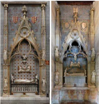
One of the most particular characteristics of Queen Elisenda's tomb is the fact that consists of two perfectly symmetrical constructions that lean on the same wall. The former is located within the church by the altar, and the latter makes up a little space in one of the sides of the cloister. The one within the church represents Elisenda as a queen, crowned and wearing the royal shroud, while in the cloister one, she's wearing the Franciscan habit. In both cases, the main focus of attention is
the representation of the deceased lying body, which in the church can be accessed by the whole congregation, while in the cloister it can only be approached by the nuns. This particular disposition depicts the queen's life, who retired from public life in the Clares' Monastery that she founded.
Figure 1. The both faces of the monument. Left, the interior of the church. Right, the cloister part.
2.2 Restoration needs. Current condition
Throughout time the monument has undergone several pictorial interventions. In the beginning of the 20th century, the part of the monument located in the church suffered an unfortunate renovation following the neomedieval style. This intervention destroyed the background gothic mural until then preserved, and all the structure and figurative elements of this part of the monument were repainted. However, this part of the monument shows a good state of conservation.
On the other hand, in the cloister, the monument keeps its original features, probably because, until recent days, its access was restricted to the nuns that lived in the convent. But this part of the monument is quite deteriorated. The stony structure have been weathered, not only the sculptures but also in the gothic tracery. Likewise the polychromatic background mural suffered important damage.
In this situation the Institut Municipal del Paisatge Urbà i la Qualitat de Vida (Local Institute for Urban Landscape and Quality of Life) commissioned the studies prior to the restoration of the monument. A polychromy analysis was carried out, as well as a study about the execution techniques and state of conservation of the different elements of the monument. But the most significant aspect of these works is that they were applied to both parts of the monument (the cloister and the church).
Before establishing the restoration project, among other works, the elaboration of a virtual model was proposed to recreate the formal and chromatic aspects of the monument in its original state.
3. WORK AIMS
The working group responsible for the monument restoration needed accurate and metric graphic information. These “documents” (2D o 3D models) should show both the current state of the monument and the relationship that have the elements on the two sides of the monument. In this way the monument's construction processes can be set.
So, one of the objectives was to generate a theoretical 3D model which reflects the current reality. This model will have a dual role, on one hand it will be a support for rehabilitation work. On the other hand, it will allow to disseminate this heritage element to the visitors while the works were carried out.
Likewise, the 2D representation of elevations and sections of the monument will be obtained, which will make easier the analysis of symmetry and the possible construction process. In order to take a survey as complete as possible the integration of different data collection techniques is proposed. What will also allow to compare results and, thus, establish protocols for using them in function of the models and the necessary accuracy for this type of work.
4. METHODOLOGY. DATA OBTAINED.
The methodologies used are: Topography techniques to establish the referenced positions. Digital photogrammetry allows to obtain rectifications, orthophotography and a 3D model by stereophotogrammetry. A Terrestrial Laser Scan (TLS) was used to obtain a dense colored point’s cloud model.
4.1 Topographic works
The tomb presents, as stated before, two faces of the same wall. This fact forced at first the development of a topographic methodology that would allow georeferentiating both sides. Thus, there would be enough data to lay out the spatial information available on each part of the monument, while obtaining a model that would relate the elevations or different elements on the both faces of the tomb.
The equipment used in topographical survey was a non prism total station model Leica 705.
The first task consisted in observing a traverse at both sides of the monument. Thus a sole reference system was established and, therefore, the different works at both sides could be related and the geometry of the whole piece drawn.
After that, from the traverse stations, the complete survey with the most significant elements (cornices, arch vertices, sculpture stands, etc.) was obtained.
4.2 Photogrammetry
In the photogrammetric case, a non-metric reflex digital camera Nikon D300S with a 20mm 2.8 AF lens, was used to take the necessary images for the different works of rectification and restoration.
The photographs were taken considering the camera at use and a series of photographic criteria, spatial limits when positioning the camera and accuracy to achieve. In case of photogrammetric restitution, the most adequate is to use convergence
photographs; this fact was taken considered when the images were taken.
In order to cover the tomb, the photographs were divided in two strips, in each side of the monument, with 60-70% longitudinal and 50% transverse overlapping. What has finally resulted 14 stereoscopic pairs for the interior and 10 for exterior of the church.
In order to do the photogrammetric rectification, the software developed by the authors was used. Conventional photographs were used after their distortion correction. In this process two reference planes have been considered. The result was extremely high resolution rectificated models (1mm/pixel) for these planes.
In the stereophotogrammetric case, the software TOPCON Image Master has been used to generate the models. The characteristic lines were drawn, basically the ones considered as rupture lines, such as the edges of the different architectural elements and the base of the statues. Then, these lines, together with the model correlated with a very dense mesh (step 1cm), were used to define the final photogrammetric model that was edited and used to color and obtain orthophotographs.
These are not complete in some areas due to occlusions and bad model, so they have been completed with partial rectifications.
Figure 2. Orthophotography vs photograph.
The surface model, figure 3, was employed to establish the comparative analyses between the two survey methodologies: digital photogrammetry and laser scan. It has a precision of 3mm in depth.
Figure 3. DSM by digital photogrammetry. International Archives of the Photogrammetry, Remote Sensing and Spatial Information Sciences, Volume XXXVIII-5/W16, 2011
4.3 Terrestrial Laser Scan (TLS)
Besides of having a model obtained by photogrammetry, new point clouds were achieved by laser scanning.
A general model was generated using the Riegl LMS Z410 and, the laser scanning data for a detail model of the sepulcher and the sculptures have been collected with a sensor based in optical triangulation, MINOLTA Vivid 910, since it get a best accuracy (Fontana et al., 2002; Fowles et al., 2003)
In the cloister part, due to the closeness between the gate and the monument was necessary to capture the data in two levels, which coincided with the ground and the first floor of the cloister. In the interior of the church this problem is avoided.
The sensor was installed, in the lower part scanning the wall from two lateral positions and a front position, which provided clouds horizontally and vertically. From the first floor, the two laterals scanning had a slightly low angle. No targets were used for georeferenciation, just the well-defined details provided by the model itself. A Nikon D100 camera colored the point clouds captured by the TLS.
The main problems consisted in the excess of obliquity of some of the captures due to the narrowness of the space. The room, 3.50 x 3.15 m of area, did not allow installing the scanner far enough to reach the total height (more than 9 m). From the first floor the captures were very close to the monument in order to cover the maximum width and avoid such obstacles as the banister that protected the area.
The most detail scanning data, with a resolution of 2.5mm on the object, of the tomb and the first level of the sculptures, were capture, as mentioned above, with a MINOLTA Vivid 910. Between the consecutive scanning there was an overlap of 50% of the surface. This prevented the completion of the scan of the shadow area, which was caused by the inclination of the camera in the upper zone of the tomb. Despite this, the equipment was able to gather lateral information on the figures. The working distance ranged 1 to 2m, with the highest resolution possible as to allow 60 partial scans in the church side, and 46 in the cloister. These point clouds would be then registered and georeferentiated. Therefore, a point cloud, characterized by its great density and color, could be extracted.
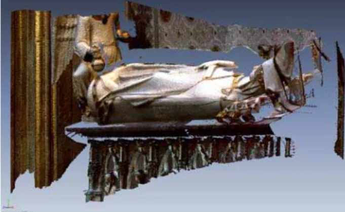
Colour (RGB value) was assigned automatically to the scanned points, in the general cloud thanks to the digital camera mounted on the Riegl laser scan, and a Minolta V9i internal camera, of less resolution than the external one. So, the images taken for the photogrammetric process have been mapped using the DLT (Remondino et al., 2009), figure 4.
In this last case, the point clouds were affected by holes in the zones coincided with the deep-red colour on the wall. Several studies show as the colour of the target object influences on the laser beam devolution and in some cases the not return of the wave (Clark and Robson, 2004; Gielsdorf et al., 2004; Núñez et al., 2005)
As well, the orthophotographs have been obtained.
Figure 4. Laser scanning detail.
5. MODELING PROCESS
The management of the data processed has allowed to obtain different result very useful to elaborate the rehabilitation project.
5.1 3D model and vectorial CAD data.
From the point clouds obtained with the laser scanner and with the digital photogrametry two models have been generated.
In the case of photogrammetry, as has been said above, the model was obtained by correlation using stereo photogrammetric models. In order to support the process by the computer, the mesh generated had a resolution of 1cm, in other case, with the computer that was being used it was impossible to manage the models.
To process the laser scanning data INUSTech Rapidform software was used. The mesh was create by triangulation for the Riegl data, while Minolta data were imported as triangulation directly.
The problem, in both cases, is the irregularities that exist in the models. They create “picks” in the sections and not represent the contour rounding.
Line drawing: The data obtained allowed establishing the position of each of the elements that are part of the monument. In order to do so, an image was drawn with scanned data that lead to a frontal projection. The generation of this image, from the orthogonally visualization of the points cloud to the background wall, allowed establishing the actual measures of the different elements.
The points from the topographic survey were added to this image to determine the working scale and to confirm the correct position of each of the elements with respect to the whole.
Hereby a base document (template) was generated to draw the lines, figure 5, that determine each of the edges of the geometrical design of the arcature, and the different parts of the monument (cornices, pilasters, stands for the statues, etc). International Archives of the Photogrammetry, Remote Sensing and Spatial Information Sciences, Volume XXXVIII-5/W16, 2011
Figure 5. Linedraw obtained in the cloister.
In order to graphically reconstruct the monument it was essential to determine those elements that, due to their small size with respect to the rest of the monument, were not sufficiently detailed by the general scan. In these cases the detail model was used.
This final definition was established with the aid of detailed photographs and manual drawings with specification of the actual dimensions on the different sections of the arcature. The sculptures were defined by means of profiles generated from a scan image and further complemented by the details shown in the photogrammetric data and products.
Thanks to all these data, the entire monument was reproduced with accuracy better than 5mm-1 cm.
5.2 3D theoretical model of the monument architecture
The possibility to have a theoretical model is a very useful tool in the restoration processes. This model would pick up the geometric shapes that the different elements of the monument should have in their initial state.
This model has been elaborated taking like base the results obtained previously and described in the above sections.
The triangulated models have allowed to create vertical and horizontal sections to establish the vertical reference depth planes of the monument.
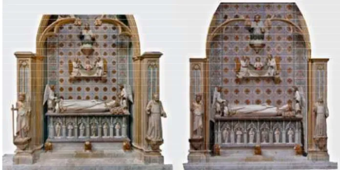
Figure 6. 3D model of both faces of the monument.
On the other hand, applying the topographical, photographic and laser scanner information the Gothic tracery in a 2D vertical plane has been generates. In this way the heights and the basic geometry of the different parts of the monument has been generated on an orthogonal front view. Combining the geometric information of the 2D vertical plane with the different depth planes the final 3D theoretical model has been achieved. This model was build with NURBS surfaces applying Rhinoceros 4.0 software that allows capturing all the geometry defined in 3D with high performance, figure 6.
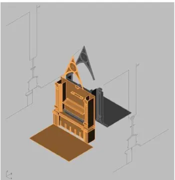
The elaboration process of the virtual model is shown in the figure 7.
Figure 7. Process schedule.
6. COMPARING THE METHODS. RESULTS
The geo-referenced clouds have a difference regards the control points of millimeters, so the models are good enough to be compared to each other.
The scan in the lower part of the monument allowed determining a more accurate mesh model, with 2mm resolution, while the photogrammetric one was of 1cm. So the first process was homogenized the two meshes to 1cm resolution.
After that, in order to analyze of the results obtained by digital photogrammetry and 3D digitizer, longitudinal and transverse sections each 20cm have been used. Hereby 20 sections were obtained.
When the sections are compared it can be seen that the ones from the photogrammetric DSM are more rounded, whereas the obtained from the laser scanning data have a zigzag appearance since the lines pass through all points measured. Another clear effect can be seen in the construction of triangles, in photogrammetry break lines were drawn explicitly by the operator, and it causes a better suited of the triangles to the model. This effect would not be remarkable if the original resolution of the laser scanning cloud had been kept. The accuracy in depth measurement is higher using a optical triangulation laser scanner like Minolta. This can be seen more in the sculptures model than in the tomb. If the ToF scan is use (the Riegl used for the general model) the best result would be achieve by photogrammetry.
In any case, the differ from each model a maximum of 1cm between sections counterparts, major differences occurring only in areas difficult to capture, as in folds and areas tangents. This difference would not cause visible change in the orthophotographs obtained by the two techniques.
6.1 Results
From the results obtained from the geo-referencing of 3D data could be observed how the elements of the monument were located on both sides of the wall.
One thing that surprised is that this wall is only 11cm thick. This fact confirms that the wall was made on both sides at once. The tomb with a total width of about 80cm is unique and the center wall rests on top.
The width of this wall and the positions they take the trays that support the central sculpture and media images of the Pantocrator, to think that necessarily had to be built in parallel as anchors to secure the brackets to the wall and have a correct functional stability have to be locked between them.
From the start of the Gothic tracery, and in the frontal plane in which it develops, begin to define different heights of the supporting elements of the sculptures, the bases of them are approximately 30cm upper in the cloister than the church. Still maintaining the geometry of gothic arches and is preserved as the main triangular nerve in both width and height.
This fact finds that the construction was carried out by both sides at once and that at the time of the construction of archery adapting to space which is already the height of the nave of the church is much larger than the lower hall the cloister and therefore this becomes more slender in the interior of the church.
The differences can be found in the positions of the various elements that rely on the shared wall are below the centimeter, similar to the RMS of the measurement tools used.
7. CONCLUSIONS.
The work showed in this paper is part of the investigation on the methods to get information of cultural heritage elements, and the processes to obtain complete and accurate 3d models. In this case digital photogrammetry, laser scanning, topography and Cad modelling have been used to obtain all the necessary information to know, better, the building process of one of the most important monuments in the Pedralbes monastery (Barcelona, Spain).
Two 3D models have been obtained of the complete monuments, one from the triangulation of the laser scanning point clouds and other from the refined of these surfaces, the sections extracted from the clouds and the topographic and photogrammetric data.
Moreover the cad model has been achieve by the integration of the data from the photogrammetry and laser scanning, with the support of the topography data in order to register and georeference all the information. From these data the orthophotography of the lower part of the monument, corresponding with the tomb, has been created.
From the models it has been possible to check that the wall between the two parts of the monuments is much thickerthan it would be though for constructions in the 14th century, so it confirms that the wall was made on both sides at once.
From the results of the comparison between models obtained by both techniques can be concluded that both, digital photogrammetry and laser scanning, can be used successfully to obtain the documentation for a rehabilitation, restoration or preservation project. But both of them have the same drawbacks such as occlusions and the big quantity of data that make difficult the data management.
An element to considerer to use one or other is the cost of the instruments, while in the data capture by photogrammetry an amateur digital camera can be used the laser scanning data collecting needs a special sensor of a high price. A drawback of the photogrammetry is that control points are necessary to obtain the orientation parameters and build the model by correlation.
In comparison with other techniques, the use of digital photogrammetry and laser scanning allows obtaining 3D models efficiently and in detail even under unfavourable conditions.
REFERENCES
References from Journals:
Blais F., 2004. Review of 20 years of range sensors, Journal of
Electronic Imaging, 13 (1), pp.231-243.
Fontana R., Greco M., Materazzi M., Pampaloni E., Pezzati L., Rocchini C., Scopigno R., 2002. Three-dimensional modelling of statues: the Minerva of Arezzo. Journal of Cultural Heritage, 3, pp.325-331.
Fowles P.S., Larson J.H., Dean C., Solajic M., 2003. The laser recording and virtual restoration of a wooden sculpture of Buddha. Journal of Cultural Heritage, 4, pp.367-371.
Lambers K., Eisenbeiss H., Sauerbier M., Kupferschmidt D., Gaisecker T., Sotoodeh S., Hanusch T., 2007. Combining photogrammetry and laser scanning for the recording and modelling of the Late Intermediate Period site of Pinchango Alto, Palpa, Peru. Journal of Archaeological Science, 34, pp. 1702-1712.
Pavlidis G., Koutsoudis A., Arnoutoglou F., Tsioukas V., Chamzas C., 2007. Methods for 3D digitization of Cultural Heritage. In: Journal of Cultural Heritage, Vol 8, pp. 93-98.
Pieraccini M., Guidi G., Attzeni C., 2001. 3D digitizing of cultural heritage. Journal of Cultural Heritage, 2, pp. 63-70.
Remondino F., El-Hakim S.F., 2006. Image-based 3D modeling: a review. Photogrammetric Rec. J., 21 (115), pp. 269–291.
Yastikli N., 2007. Documentation of cultural heritage using digital photogrammetry and laser scanning. Journal of Cultural
Heritage, 8, pp. 423-427.
Yilmaz H.M., Yakar M., Gulec S.A., Dulgerler O.N., 2007. Importance of digital close-range photogrammetry in documentation of cultural heritage. Journal of Cultural
Heritage, 8, pp.428-433.
References from Books:
Mestre J., Adell J., 2001. Monestirs de Catalunya (in Catalan). Editorial 62, Barcelona.
Schenk T., 1999. Digital Photogrammetry Volume I. Terra Science, Laurelville, OH.
References from Other Literature:
Agnello F., Lo Brutto M., 2007. Integrated surveying tecniques in cultural heritage documentation. The International Archives of the Photogrammetry, Remote Sensing and Spatial
Information Sciences, Zurich, Switzerland, Volume
XXXVI-5/W47
Bradshaw G., 1999. Non-Contact Surface Geometry Measurement Techniques, Image Synthesis Group, Trinity College, Dublin.
Clark J., Robson S., 2004. Accuracy of measurements made with a Cyrax 2500 Laser Scanner against surfaces of known colour. In: ISPRS XX Congress- Commision IV, Istambul, Turkey.
Demir N., Bayram B., Alkış Z., Helvaci C., Çetin I., Vögtle T., Ringle K., Steinle E., 2004. Laser scanning for terrestrial photogrammetry, alternative system or combined with traditional system? In: Comisión V, WG V/2 ISPRS, Istambul, Turkey.
Fröhlich C., Mettenleiter M., 2004. Terrestrial laser scanning -new perspectives in 3D surveying. In: M. Thies, B. Koch, H. Spiecker, H. Weinacker (Eds.), Proceedings of ISPRS Working
Group VIII/2, Freiburg, pp. 7-13.
Gielsdorf F., Rietdorf A., Gruending L., 2004. A concept for the calibration of terrestrial Laser Scanners. In: FIG Working Week 2004, Athens, Greece.
Núñez A., Buill F., Múñoz F., 2005. Comportamiento de un sensor láser escáner. In: 6ª Semana Geomática, Barcelona, Spain.
Remondino F., Pelagotti A., Del Mastio A., Uccheddu F., 2009. Novel data registration techniques for art diagnostics and 3D heritage visualization. In: 9th Conference on Optical 3-D
Measurement Techniques 2009, Vienna, Austria.
Sgrenzarolim M., 2001. Photorealistic 3D reconstruction of large, real objects using laser scanning and still images. In: Proceedings of 7th International conference on Virtual Systems
and Multimedia, Berkeley.