Effect of Physical Constraints on Load
Frequency Control of Deregulated Hybrid
Power System Integrated with DFIG Wind
Turbine
Aditi Gupta#1, Yajvender Pal Verma*2, Amit Chauhan#3
#
Electrical & Electronics Engineering Department, Mechanical Engineering Department UIET, Panjab University, Chandigarh, India.
1
aditi_2881@rediffmail.com
3
drchauhan98@gmail.com
* Electrical & Electronics Engineering Department UIET, Panjab University, Chandigarh, India.
2
yajvender_verma@yahoo.com
Abstract -This paper presents a generalized model for load frequency control (LFC) design in a hybrid multi-area deregulated power system including physical constraints. Renewable energy source named doubly fed induction generator (DFIG) based wind energy source is integrated into the system that provides the modified emulating inertial control and reduces the deviations in frequency and tie-line power, following a transient load perturbation. In addition to this, the three basic physical constraints viz. generation rate constraints (GRC), speed governor dead band and communication or time delay have been imposed on the power system that affect the system’s security, reliability and integrity. To get the better performance of the various controllers in power system, their gains are optimized using integral square error (ISE) technique. Present simulation studies reveal that the system’s performance becomes better by the inclusion of DFIG based wind turbine. It is also shown that the dynamic performance of the system becomes poorer by adding physical constraints but it is a more realistic approach.
Keywords- Automatic Generation Control (AGC), LFC, Deregulated system, Bilateral contracts, Disco participation matrix (DPM), DFIG, GRC.
I. INTRODUCTION
Under the new trend of power system restructuring [1, 2], AGC that facilitates the bilateral contracts [3, 4, 5] in the power systems, becomes one of the most important ancillary services to be controlled. Few years back, focus has shifted to the greener and cleaner sources of power generation to reduce the harmful gas emissions and global warming. Wind power source is the most significant component of such resources. But wind energy systems generally do not participate in the frequency regulation and tie-line power regulation and hence have lesser role in AGC [6, 7]. So, more controlled & advanced wind turbine named DFIG based wind turbine may be used which can replace the conventional fixed speed induction generator wind turbines [7, 8]. Conventional wind turbines have significant amount of kinetic energy stored in the rotating mass of the blades of the turbines. This energy does not contribute to the inertia of the grid. A technique is suggested in [9, 10] to emulate additional inertia to the system. Here, frequency control includes the inertial control, kinetic energy stored in the rotating parts of turbine and proportional control. Once the rotor speed varies from the optimal value following a disturbance, all the control actions recover it back and system frequency returns to its nominal value. In [11], the control strategy is defined with a combination of static converters control and pitch control, to regulate primary frequency. A new frequency control support is suggested in [12] that is proportional to the frequency deviation and uses the kinetic energy of turbine blades to reduce the frequency deviations. Impact of different settings of governor and inertia on DFIG’s contribution in frequency regulation are suggested in [13]. Literature review shows that most of the AGC studies done on deregulated environment and including renewable resources considers the simplified models of hybrid multi-area power system only. A simplified approach is adopted in all the research works for deregulated environment by neglecting the physical constraints. Accurate and precise performance of the AGC in power system cannot be analyzed by neglecting some of the useful physical constraints [14, 15]. These constraints are the inherent characteristics of the power system and they must be modeled into the system to have the more real and practical aspect of its performance. These constraints are generation rate constraint (GRC), speed governor dead band and communication or time delays.
physical constraints are included in the system to analyze its actual performance. The effect of increased communication delay is also studied in this paper. Wind penetration of 10% is used for 2% load perturbation in each area and in both the areas.
The rest of the article is organized as: In section 2, the basic idea of multi-area deregulated power system is given. Section 3 presents the DFIG based wind turbine and its modelling. The basic physical constraints imposed on power systems are explained in section 4. In section 5, the power system which has been taken for investigation is discussed. In section 6, simulation results are shown for three test cases and their discussion is also included. Section 7 comprises of the conclusions.
II. MULTI-AREA DEREGULATED POWER SYSTEM
After restructuring of power systems, emergence of new companies has taken place viz. GENCOs, TRANSCOs, DISCOs and independent system operator (ISO). As there are number of GENCOs and DISCOs in deregulated systems, agreements are made between GENCOs and DISCOs within the control area or with the interconnected GENCOs and DISCOs in other area to supply the power. Mathematically, these transactions are represented in the form of generalized model as DPM [1], which gives the clear visualization of these contracts. Number of rows in DPM is equal to the number of GENCOs and number of columns is equal to the number of DISCOs in the power system.
The entries of DPM are contract participation factors (Cpfij), which represent the fraction of total load
contracted by any DISCO j towards any GENCO i. The DPM for a two area hydro-thermal system, having two GENCOs in thermal area and one GENCO in hydro area is given in equation (1).
11 12 13
21 22 23
31 32 33
...
Cpf
Cpf
Cpf
DPM
= Cpf
Cpf
Cpf
...
(1)
Cpf
C
...
pf
Cpf
Sum of all the entries in a column of this matrix is unity. Whenever a load change takes place in deregulated system, it is taken care off in its own area, as defined by DPM. In addition to this, new information signals from DISCOs to GENCOs which are not in their area will flow that adjust the scheduled flow over the tie lines. The change in tie line power derives area control errors (ACEs) for the control areas involved. Depending upon the participation of ACE signal of that particular area in the AGC, a new participation factor is evolved known as ACE participation factor (apf) [1,3]. On the basis of all these above said ideas, generalized block diagram of the two-area system represented by equation (1) is given in Fig. 1.
Under steady state conditions, the power equations of the deregulated system are as follows [4]: The scheduled tie line power is
sch tie
P
= (Demand of DISCOs in area 2 from GENCOs in area 1) – (Demand of DISCOs in area 1 from GENCOsin area 2)
13 23 D1 31 32 D2
...
= (Cpf + Cpf )
Δ
P
−
(Cp
f + Cpf )
Δ
P
...
...
..
(2
)
Actual tie line power is
(
)
act
tie 1 2
...
2
π
T
P
=
d
f - df
...
(3)
s
.
So, at any instant, the tie line power error is given by equation (4)
sch act
tie tie tie
...
dP
=
P
−
P
..
(
4)
This signal generates the respective ACE signal, same as in traditional scenario and is given as
1 1 1 tie
...
ACE = B df
+ dP
....
..
(5)
r1
2 2 2 12 tie 12
r 2
...
...
P
...
ACE = B df + a dP ,
wh
ere
a
...
(6)
P
...
−
=
Now, the total power supplied by ith GENCO is
N=2(DISCOs)
i ij D1 i UCi UCi
th
j=1
where
is uncontracted demands of
III.DFIGBASED WIND TURBINE
Now a days, it has become a global concern to include greener and cleaner sources of energy in the hybrid power generation to meet the increasing load demand and to reduce the global warming. Wind power technology is one of the most significant renewable resources of energy. But high percentage of wind power in overall hybrid generation may cause more fluctuations in grid frequency following the perturbations. The rate of change of frequency following a disturbance is directly proportional to the change in generation caused by that disturbance and inversely proportional to the kinetic energy stored in the power system. By the use of DFIG based wind turbines, their contribution to system inertia increases significantly. The increased system inertia decreases the frequency deviations following a perturbation [6]. These DFIG based wind controllers manipulates dynamically the position of DFIG rotor flux vector to slow down the generator, following a surge in the power output, which reduces the decrease in frequency due to loss of generation [10]. A block diagram of DFIG based wind turbine control is shown in Fig. 2 including conventional or emulating inertial control. This controller adapts a power set point Pf* that is proportional to the change in grid frequency df and the rate of change of grid frequency df/dt [7]. The controller provides another power set point Pw* that is based on the measured speed and electrical power. Combination of Pf* and Pw* contributes to PNC, power output of DFIG based wind turbine. The two power set points Pf* and Pw* are described in mathematical form as follows [7]: The power set point Pf* is given by:
*
f fd fp
...
df
..
P = -K
- K
df
...
dt
.
(8)
where Kfd is the constant weighting the frequency derivative and Kfp weights the frequency deviation itself. df is the frequency deviation behind a high pass filter so that the control strategy becomes independent of permanent frequency deviation. Also, Pf* is built on the basis of change in frequency using a washout filter. This filter is used because DFIG responds to frequency deviations following a transient disturbance by using its stored kinetic energy and not responds to the permanent disturbances. So,
* ''
f
...
...
1
P =
df ,
(9)
R
where
R is droop consta
nt
...
...
...
df is the frequency deviation measured in the interconnected area between non-conventional generators and rest of the power system. Once the frequency transient is over, the equivalent non-conventional machine recovers the optimal speed. So, speed is forced to track a desired reference speed by power reference that is given by:
* * *
w wp s wi s
...
P
= K
(w - w ) + K
(
w -
w )dt
...
.
..
(10)
where Kwp and Kwi are constants of PI controller which are chosen to allow fast speed recovery and transient speed variations which causes the non-conventional generators to inject required active power so as to reduce the transient frequency deviations. Now, the total power output of DFIG based wind turbine is given by:
* *
NC f w
...
P
= P + P
(11)
To analyze the effects of inertial control on the whole power system, equation (12) is considered.
T g NC tie D
...
df
2H
= P - Ddf = P +
P
- P -
Δ
P
-
Ddf
...
...
.
(12)
dt
where PT is total power generated by hybrid power plant, Pg is the power generated by conventional power plant and D is damping factor.
(
)
*
fd g w tie D fp
...
df
(2H + K )
P
+ P - P -
Δ
P - D + K
df
...
(13)
d
t
...
=
* * *
g w tie D
...
df
2H
P + P - P -
Δ
P - D df
...
(14)
dt
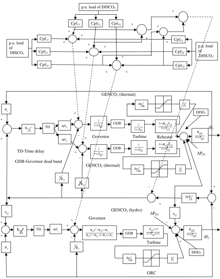
Fig. 1. Two area hydrothermal deregulated systems with DFIG based wind turbine considering constraints. 1 1+sTg1 du dt 2 B
2πT s 1 1+sTg2 du dt GDB GDB 1 s 1 s TD TD 1 B 11 1 R 12 1 R GDB 1 s DFIG2 DFIG1
∆PD1
∆PD2
Governor Turbine 1 1+sTt1 1 1+sTt2 Turbine -T s+1w 1/ 2T s+1w
Reheater 1+sK Tr1 r1 1+sTr1
1+sKr2 r2T 1+sTr2
GRC
GENCO3 (hydro)
GENCO2 (thermal)
GENCO1 (thermal)
du dt df1 df2 Kp1 1+sTp1 Cpf11 Cpf21 Cpf31 Cpf33 Cpf23 Cpf13 Cpf32 Cpf22
p.u. load of DISCO3
p.u. load of DISCO2 p.u. load of DISCO1 12 apf + 12 a + i2 K s + + + i1 K s + + + Governor _ _ 11 apf + + _ 2 apf 2 1 R + 2
d p i
2
d p 2 i
K s +K s+K K s +K +f / R s+K
+ _ _ + + + + + + + + + + + + + Cpf12 + _ _ _ 12 a + Kp2 1+sTp2 GDB-Governor dead band
So, this inertial control scheme provides a modified system inertia H*, which can be established carefully by varying Kfd and Kfp. Positive values Kfd increases the values of H* inside some feasible margins. Positive values of Kfp provide a better damping of frequency oscillations.
The total active power generated by wind turbine is PNC, which is compared with maximum power output PNCref, obtained by maintaining reference rotor speed. This is given by:
(
)
3NCref
1
r pmax s...
P
=
ρ
A
C
w
...
(15)
2
where ρ is density of air (kg/m3), Ar is rotor area (m2), Cpmax is maximum Cp(λ) curve at pitch angle β equal to zero, ws is the speed of wind.
For this paper, the values of these parameters are taken as same for GE 3.6 MW turbine as given in ref [16].
Fig. 2. Emulating inertial control scheme based DFIG wind turbine.
IV.PHYSICAL CONSTRAINTS ON HYBRID POWER SYSTEMS
AGC is one of the most important and noteworthy ancillary services of hybrid multi-area power system. So, it becomes very important to study this AGC in real-time environment. In most of the researches, a simplified approach of multi-area power system by neglecting all or some of the physical constraint is considered. Although, it is very difficult and un-useful to consider all the dynamic constraints in the synthesis of control system, but to get the perfect and accurate perception of AGC, the basic constraints imposed by the system dynamics must be considered [14, 15]. These constraints may be due to filters, communication channels, governor units, crossover elements and penstocks, depending upon the type of generating unit chosen like thermal, hydraulic et. al. These constraints reversely affect the performance of AGC by increasing the settling time and peak overshoots. The three basic constraints that affect the power system dynamics are GRC, governor dead band and time delay [14].
A. GRC
Due to thermo dynamical and mechanical movements, the generation of the generating units is limited to some specified minimum and maximum rate. It is not realistic to ignore the delays and GRC due to crossover elements in thermal plants. GRC for thermal units is considered as 3% per minute for both minimum and maximum limit. For hydro unit, it is 360% per minute and 270% per minute for minimum and maximum limit respectively.
B. Governor Dead Band
When input signal is changed, the speed governor cannot immediately respond but wait until the input signal reaches a particular value. This constraint is governor dead band. A dead band is basically an interval of
1
1+sT
a wpK
w i
K
s
1
2 s H
+
+ + +
+ _
+
_
ws
w* Pw*
Pf*
PNCref
PNC
df df
w
w sT 1+ sT
df
r
1
1+sT
1
R
w P
Pmax
signal domain or band where no action occurs or the system is dead. It is expressed as percentage of rated frequency. The standard value is 0.06% that is 0.036 Hz. It is the result of mechanical friction and backlash. C. Communication Delay/ Time Delay
By the expansion of physical setups and hence the complexity of the power systems due to deregulation, it is not realistic to ignore the communication delays in the AGC synthesis. So, it is considered in the present work to support the ancillary services.
V. SYSTEM UNDER INVESTIGATION
The investigated deregulated system consists of two generating areas. Area 1 is thermal area with two GENCOs of equal capacity and with single stage reheat turbine. Area 2 is hydro area with one GENCO and with electric governor. Area 1 has two DISCOs and area 2 has one DISCO. The nominal parameters are given in appendix A. The optimum values of gains of all the controllers are obtained using integral square error (ISE) technique. According to this technique, the cost function J which is the performance index is required to be minimized and is given by:
(
2 2 2)
tie 1 2
...
J =
d
P
+ df + df
dt
...
....
.
(16
)
where dt is the small time interval of sample.
To investigate the real time performance of the controllers, the three physical constraints are included in the model. These are GRC, governor dead band and time delay. The optimum values of gains of integral controllers (Ki1 and Ki2) are again obtained using ISE technique. In addition to this, the hybrid power system includes the DFIG based wind power plant. To enhance the participation of DFIG in frequency control following the transient disturbances, optimum values of speed control parameters (Kwi and Kwp) of DIFG based wind turbine are obtained, again by using ISE technique. All these optimum values are given in Table 1.
TABLE I
Optimum Controller Settings Using ISE Technique
Type of the system
Electric governor Integral controller DFIG based wind turbine
(10% wind penetration) Without
constraints
With constraints
Name of gain Kd Kp Ki Ki1 Ki2 Ki1 Ki2 Kwi1 Kwp1 Kwi2 Kwp2
Value of gain 3.9 3.9 4.6 0.4288 0.036 0.1232 0.0147 0.01 0.046 0.02 0.9
The system explained above is analysed in deregulated environment, which is as follows:
Each DISCO demands 0.01 p.u. MW power. DPM will have three rows corresponding to three GENCOs and three columns corresponding to three DISCOs and is as follows:
...
0.3 0.4
0.
...
5
DPM = 0.3 0.5 0.2
(17)
0.4
0.1 0.3
...
It is chosen on the basis of open market economics which is continuously changing. However, in the present paper, only one DPM is considered for analysis purpose, as given in equation (17). For this DPM, the GENCOs schedule and tie line power schedule is given by
GENCO1(sch) = (0.3+0.4+0.5)*0.01 = 0.012 p.u. MW
Similarly, GENCO2(sch) = 0.01 p.u. MW
GENCO3(sch) = 0.008 p.u. MW
And Ptie(sch) = [(0.5+0.2)-(0.4+0.1)]*0.01 = 0.002 p.u. MW.
It is also considered that the area participation factors (apfs) of thermal area depends upon the scheduled generation of GENCOs and tie line power [1]. So, apfs are chosen as:
apf11 for GENCO 1 =
(
)
0.012
12
13
0.012 0.01
+
=
apf12 for GENCO 2 =
(
)
0.01
1
It is to noted that apf11+ apf12 = 1
For hydro area, apfs of all the GENCOs are divided equally. So, apf2 for GENCO3 = 1.
VI.SIMULATION RESULTS
Simulations have been conducted for the two area hybrid deregulated power system given in Fig 1. DFIG based wind turbine is included in the system which is given in Fig 2. All the systems are simulated using SIMULINK in MATLABR2013. The following test cases are considered:
Case 1: System without any physical constraints
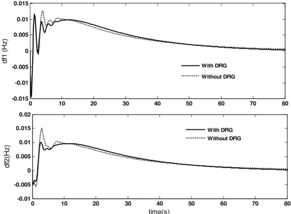
The two area system shown in Fig. 1 is considered by ignoring all the three constraints. Effects of adding DFIG based wind turbines to the system, area wise or in both the areas are studied. The wind penetration level of 10% is used and 2% load perturbation is considered in each area and in both the areas. The dynamic responses are plotted in Figs. 3 to 5. The DFIG based wind turbine responds quickly to the disturbances by providing active power support proportional to the change in frequency. It provides the inertial support by reducing the rotor speeds and injecting larger kinetic energy into the system thereby compensating load perturbation. So, DFIG improves the dynamic response of the system following a load perturbation, in terms of peak overshoots and settling time, as shown in Figs. 3 to 5.
Fig. 3. Frequency responses of area 1 and 2 for 2% load perturbation in area 1.
0 10 20 30 40 50 60 70 80
-0.015 -0.01 -0.005 0 0.005 0.01 0.015
df
1 (
H
z)
With DFIG
Without DFIG
0 10 20 30 40 50 60 70 80
-0.01 -0.005 0 0.005 0.01 0.015 0.02
time(s)
df
2(
H
z
)
Fig. 4. Frequency responses of area 1 and 2 for 2% load perturbation in area 2.
Fig. 5. Deviations in frequency (area 2) and in tie line power for 2% perturbation in both areas.
0 5 10 15 20 25 30 35 40 45 50
-0.03 -0.02 -0.01 0 0.01 0.02
df
1 (
H
z
)
0 5 10 15 20 25 30 35 40 45 50
-0.05 -0.04 -0.03 -0.02 -0.01 0 0.01
time (s)
df
2
(
H
z
)
With DFIG Without DFIG
With DFIG Without DFIG
0 5 10 15 20 25 30 35 40
-0.06 -0.05 -0.04 -0.03 -0.02 -0.01 0 0.01
df
2
(
Hz
)
0 5 10 15 20 25 30 35 40 45 50 -0.005
0 0.005 0.01 0.015 0.02 0.025
time (s)
d
P
ti
e
(p
.u
.) With DFIG
Fig. 6. Deviations in frequency (area1) and in tie line power for 2% perturbation in area1.
Fig. 7. Frequency responses of area 1 and 2 for 2% load perturbation in both areas.
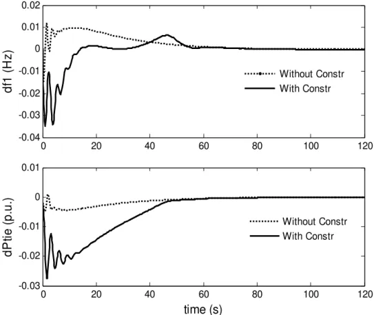
Case2: System including physical constraints - Real time system
All the three constraints are added to all the areas of the hybrid power system. DFIG based wind turbine is also included in the system. The dynamic responses are plotted in Figs. 6 & 7. The generations of the two GENCOs are plotted in Fig. 8 under different scenarios. It has been seen that the system including all the constraints deteriorates in its performance as compared to the one with no constraints. The overshoots,
0 20 40 60 80 100 120
-0.04 -0.03 -0.02 -0.01 0 0.01 0.02
df
1
(
H
z
)
0 20 40 60 80 100 120
-0.03 -0.02 -0.01 0 0.01
time (s)
d
P
ti
e
(
p
.u
.)
Without Constr With Constr
Without Constr With Constr
0 20 40 60 80 100 120
-0.08 -0.06 -0.04 -0.02 0 0.02
df
1 (
H
z)
0 20 40 60 80 100 120
-0.08 -0.06 -0.04 -0.02 0 0.02
time (s)
df2 (
H
z)
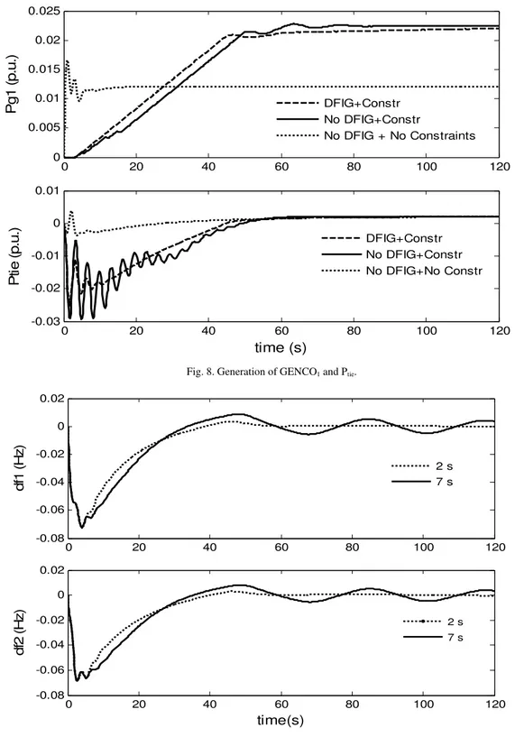
undershoots and settling times are increased. But these constraints must be included in the system so as to get the precise performance of the system. As DFIG provides inertial support in the initial stages of the perturbation, it delays the response of the thermal units. The generation of thermal units change afterwards as their inertia is large. It can be clearly seen by comparing the two sub-figures of Fig. 8. DFIG system acts more swiftly, so peak deviations are higher in the systems without DFIG. In addition to this, the system that has no constraints have lower peak deviations and settling times and have better performance even in the absence of DFIG based wind turbine.
Fig. 8.Generation of GENCO1 and Ptie.
Fig. 9. Frequency responses of area 1 and 2 for different time delays.
0 20 40 60 80 100 120
0 0.005 0.01 0.015 0.02 0.025
P
g
1
(p
.u
.)
0 20 40 60 80 100 120
-0.03 -0.02 -0.01 0 0.01
time (s)
P
ti
e
(p
.u
.)
DFIG+Constr No DFIG+Constr
No DFIG + No Constraints
DFIG+Constr No DFIG+Constr No DFIG+No Constr
0 20 40 60 80 100 120
-0.08 -0.06 -0.04 -0.02 0 0.02
df
1 (
H
z)
2 s 7 s
0 20 40 60 80 100 120
-0.08 -0.06 -0.04 -0.02 0 0.02
time(s)
df
2 (
H
z) 2 s
Case 3: Effect of time delay of communication channel
There is always some time gap between the action of various components of hydro, thermal and DFIG wind systems, which is maximum upto about 10 seconds. So, the dynamic responses for time delays of 2 seconds and of 7 seconds are compared in Fig. 9. When the time delay of communication channels is increased from 2 seconds to 7 seconds, the AGC system becomes unstable to hold the frequency and the system becomes unreliable, unstable and unsecure. As it is unrealistic to ignore this time delay, time delay of 2 seconds must be included in the system to make it more realistic as well as reliable, stable and secure.
VII. CONCLUSIONS
AGC scheme is studied for DFIG based wind integrated deregulated power system and physical constraints are also included in the system. The new emulating inertial control scheme is used for DFIG which provides inertial support to the system during transient perturbations. With this control, wind turbines become able to support the primary frequency control and emulate inertia by applying additional control loops. They use the kinetic energy stored in the form of hidden inertia of the rotating turbine blades. It is clear from the graphs that the peak deviations (overshoots and undershoots) and settling time decrease for the system having DFIG based wind turbine. ISE technique is used for optimization of integral controller gains for optimization of integral controller gains for various blocks to get the better response of these controllers.
By incorporating the physical constraints viz. GRC, speed governor dead band and time delay into the system, system’s realistic behavior can be obtained. Neglecting these constraints for easier analysis leads to invalid results and risk the system’s security and integrity. The dynamic response of the system gets poorer in terms of peak deviations and settling time, but it is the more practical and realistic analysis. The effect of increasing time delay is also studied. When it is increased from 2 seconds to 7 seconds, the system becomes unable to hold the frequency and may reach the stage of instability.
APPENDIX Various system constants of Fig. 2 & Fig. 3 are given in Table II.
TABLE II System Constants
Name Description Value
Tg1, Tg2 Governor time constant 0.08 seconds, 0.08 seconds
Tt1, Tt2 Turbine time constant 0.3 seconds, 0.3 seconds
Tr1, Tr2 Reheater time constant 10 seconds, 10 seconds
Kr1, Kr2 Reheater gain 0.5, 0.5
Kp1, Kp2 Power system gain 60, 60
Tp1, Tp2 Power system time constant 20 seconds, 20 seconds
R11, R12, R2 Regulation droop 2.4, 2.4, 2.4
Tw Water starting time 1 second
B1, B2 Frequency bias constant 0.4249, 0.4249
T Synchronizing constant 0.0866 p.u. MW/Hz
H1, H2 Equivalent wind turbine inertia 3.5 p.u. MW sec, 3.5 p.u. MW
sec
Ta1, Ta2 DFIG turbine time constant 0.2 seconds, 0.2 seconds
Tw1, Tw2 Washout filter time constant 6 seconds, 6 seconds
Tr1, Tr2 Transducer time constant for DFIG 0.1 seconds, 0.1 seconds
Pr1, Pr2 Rated power 2000MW, 2000MW
a12 -Pr1/Pr2 -1
f Nominal frequency 60 Hz
REFERENCES
[1] Parida M, Nanda J. Automatic generation control of a hydro-thermal system in deregulated environment. In: Proceedings of IEEE conference on Electrical Machines and Systems, 2005, 2(1), 952-947.
[2] Moon Y-H., Ryu H-S., Park J-K. A new paradigm of automatic generation control under the deregulated environmens. In: Proceedings of IEEE Power Engineering Society Winter Meeting, 2000, 21-25.
[3] Donde V, Pai M.A., Hiskens I.A. Simulation of bilateral contracts in an AGC system after restructuring. News letter: Power System Engineering Research Centre, PSERC Publications, 00-07, 2000.
[4] Farook S, Raju P.S. AGC controllers to optimize LFC regulation in deregulated power system. International Journal of Advances in Engineering and Technology, 2011, 1(5), 278-289.
[5] Verma Y.P, Kumar A. Load frequency control in deregulated power system with wind integrated system using fuzzy controller. Frontiers in Energy, 2013, 7(2), 245-254.
[6] Mauricio J.M, Marano A, Exposito A.G, Ramos J.L.M. Frequency regulation contribution through variable-speed wind energy conversion systems. IEEE transactions on Power Systems, 2009, 24(1), 173-180.
[8] Ekanayake J, Jenkins N. Comparison of the response of doubly fed and fixed speed induction generator wind turbines to change in network frequency. IEEE transactions on Energy Conversions, 2004, 19(4), 800-802.
[9] Morren J, Haan S.W.H., Kling W.L., Ferreira J.A. Wind turbines emulating inertia and supporting primary frequency control. IEEE transactions on Power Systems, 2006, 21(1), 433-434.
[10] Lara O.A, Hughes F.M, Jenkins N, Strbac G. Contribution of DFIG-based wind farms to power system short term frequency regulation. In: Proceedings of Generation, Transmission, Distribution, 2006, 153(2), 164-170.
[11] Almeida R.G., Lopes J.A.P. Participation of doubly fed induction wind generators in system frequency regulation . IEEE transactions on Power Systems, 2007, 22(3), 944-950.
[12] Bhatt P., Roy R., Ghoshal S.P. Dynamic participation of doubly fed induction generator in automatic generation control. Renewable Energy, 36(2011), 1203-1213.
[13] Kayikei M., Milanovie J.V. Dynamic contribution of DFIG-based wind plants to system frequency disturbances. IEEE transactions on Power Systems, 2009, 24(2), 859-867.
[14] Golpira H, Bevrani H, Golpira H. Effect of physical constraints on the AGC dynamic behavior in an interconnected power system. International Journal of Advanced Mechatronic Systems, 2011, 3(2), 79-87.
[15] Golpira H, Bevrani H, Golpira H. Application of GA optimization for automatic generation control design in an interconnected power system. Energy Conversion and Management, 52(2011), 2247-2255.