European Rail Traffic Management System – An
Overview
Dr Sajed K Abed
DeltaRail Group Limited (www.deltarail.com) Derby DE24 8HS, United Kingdom
Email: [email protected]
Abstract - This paper aims to give an overview of the European Rail Traffic Management System (ERTMS) which is currently being implemented in Europe and other parts of the world. It provides some background on this system, the objectives behind the development of the ERTMS, its architecture, different application levels of the ERTMS and brief information on its implementation in Europe and worldwide. The paper assumes the readers have a little or no knowledge of the ERTMS.
I. INTRODUCTION
The main purposes of a railway signalling system can be summarised as [1]:
• Maintaining a safe distance between following trains on the same track
• Safeguarding the movement of trains at junctions
• Regulating the movement of trains according to the service density and the speed required.
Various railway signalling technologies have been introduced over the years in different parts of the world. The European Rail Traffic Management System (ERTMS) is a signalling and train control system promoted by the European Commission (EC) for use throughout Europe. The main objectives of the ERTMS are [2]:
• To contribute to the interoperability (i.e. compatibility between track and train) of the trans-European rail network – not only inside the European Union (EU) boarders, but also anticipating the longer-term integration of Central and Eastern European networks and the corridors to Asia and the Middle East.
• To create a single market for procurement, leading to significantly reduced equipment costs and the affordability of “state-of-the-art” signalling and telecommunication.
• To optimise rail operations on a European wide-scale, encouraging profitability and customer services and contributing to overall environment, safety and energy efficiency objectives.
The ERTMS has two main components:
1. The European Train Control System (ETCS), also referred to as ERTMS/ETCS – This is an Automatic Train Protection (ATP) system which is designed to gradually replace the existing incompatible systems throughout Europe.
2. Global System for Mobile Communications-Railway (GSM-R) – this a radio system which provides voice and data communication between the track and train based on standard GSM system and using frequencies specifically allocated for railway application. The frequency bands 876-880 MHz and 921-925 MHz were allocated for the GSM-R [7]. Outside Europe, GSM-R is also operated in the 1800 MHz and 1900 MHz bands [4].
Currently there are more than 20 train control systems used across the European rail network [4]. Each system is a stand-alone and incompatible with the others. In some countries more than one train control system is used, therefore the trains should be equipped with more than one train control system to operate in one country let alone crossing the border between two different countries. For example the Thayls trains which are running between Paris-Brussels-Cologne and Amsterdam have to be equipped with seven different types of train control systems. This adds to the complexity of the overall control systems and increase operational and maintenance costs for running such system. This is why the ERTMS has been developed to replace the different national train control systems and to bring a significant advantage e.g. interoperability and reducing costs.
II. SYSTEM ARCHITECTURE
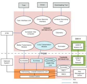
Figure 1. System architecture of the ERTMS/ETCS and its interface with the GSM-R and signalling subsystems
• Eurobalise – for unidirectional spot transmission from trackside to train.
• Euroloop – for unidirectional semi-continuous transmission from trackside to train.
• Euroradio – this provides bidirectional data transmission between the onboard and trackside assemblies via the GSM-R.
As shown in Figure 1, three types of interface specifications have been identified:
• An interface which is required for technical interoperability. This interface is referred to as Form
Fit Functional Interface Specification (FFFIS) (e.g. the interface between the Eurobalise and Eurobalise reader). This interface ensures that systems from different suppliers which meet this specification can
work together without any further precautions.
• An interface which is required for operational interoperability but not relevant to technical interoperability. This interface is referred to as Function Interface Specifications (FIS) (e.g. interface between the Train Interface Unit (TIU) and the train).
• Non-harmonised interfaces such as the interface between RBC and interlocking; this will depend on the type of interlocking to be used on an ERTMS project.
The rest of this section gives a brief description of the main components of the onboard and trackside ERTMS/ETCS assemblies.
A. Onboard ERTMS/ETCS Control-Command Assembly
Depending on the application (see Section IV below) and as depicted in Figure 1 above, the onboard ERTMS/ETCS assembly can be composed of:
1. European Vital Computer (EVC) – this is a computer-based system which supervises the train movement based on the information exchanged between the onboard and trackside ERTMS/ETCS assemblies.
2. GSM-R Mobile Unit – this unit is used for the bi-directional data transfer for ATP purposes between the onboard ERTMS/ETCS assembly and the RBC via the GSM-R network. In addition to that there is also a voice radio which provides the means of voice communication between the train driver and the signalling centre. Almost in all applications two separate mobile radios (voice and data) are used on the onboard assembly.
3. Juridical Recorder Unit (JRU) – The JRU is used to record information sent by the onboard ERTMS/ETCS (e.g. train speed, application and revocation of train brakes, messages sent/received by the onboard etc.). This recorded data can be downloaded and analysed for legal purpose after hazardous situations.
4. Train Interface Unit (TIU) – the TIU enables the onboard ERTMS/ETCS assembly to interface with train systems such as traction control, emergency and service brakes, directional controller, coupling status etc.
5. Euroradio – this provides the safe communication between the onboard and trackside ERTMS/ETCS assemblies via the GSM-R network. Through using the EURORADIO Protocol [9], the Euroradio is encoding the messages sent to the RBC and decoding the messages received from the RBC.
6. Odometry – based on the information received from speed sensors, the odometry provides train localisation information to the EVC which are then used for the train control. This information composed of train position, train speed and the driving direction.
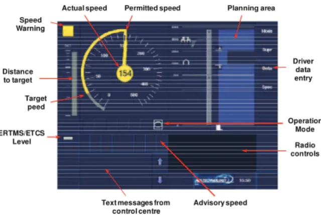
7. Driver Machine Interface (DMI) – the DMI provides the interface between the EVC and the driver. The DMI displays the driving information to the driver during the mission, acquires driver actions during start of mission and when entering train data and also displays critical failures detected at system initialisation and during the mission. Figure 2 provides an overview of the information displayed on an ERTMS/ETCS DMI.
Text messages from control centre
Radio controls ERTMS/ETCS
Level
Permitted speed
Actual speed Planning area
Target peed
Advisory speed
Driver data entry
Operation Mode Speed
Warning
Distance to target
Figure 2. Layout of the information displayed on the DMI
B. Trackside ERTMS/ETCS Control-Command Assembly
Again, depending on the application (see Section IV below), the trackside ERTMS/ETCS control-command assembly as depicted in Figure 1 above can be composed of:
1. Eurobalise – this is a spot transmission equipment which is based on a passive transponder installed in the track. The Eurobalise is used to send information to the onboard ERTMS/ETCS as the train pass over it. The Eurobalise is energised by an electromagnetic field generated by an antenna fitted onboard the train. The frequency of the magnetic field used to energise the Eurobalise is 27 MHz. Once energised the Eurobalise will cyclically send a telegram back to the train. The frequency of the telegrams sent by the Eurobalise is around 4 MHz. Depending on the ERTMS/ETCS application level (see Section IV below) the data transmitted by the Eurobalise can be fixed data or variable data.
2. Euroloop – the Euroloop is a semi-continuous transmission system which is based on a leaky feeder cable installed on the foot of the rail. Similar to Eurobalise, the Euroloop is activated by the magnetic field generated by an antenna fitted onboard the train. The Euroloop respond by cyclically sending a telegram back to the train. Whilst the Eurobalise represents a spot transmission system, Euroloop performs the function of a semi-continuous transmission system allowing transmission of information from a section of the track to the train.
3. Lineside Electronic Unit (LEU) – the LEU can be used to connect Eurobalises and Euroloops to the signalling system. It is used to transfer the status of the lineside signals into telegrams which can be transmitted by the Eurobalise or the Euroloop.
4. Radio In-fill Unit (RIU) – the RIU is used in level 1 (see Section IV below) to transfer the signalling information with regard to the main signal in the train running direction to the GSM-R Network and in turn updated information is sent to the train via the GSM-R radio channel.
5. Trackside radio communication network (GSM-R) – this is a radio network distributed along the railway lines which is used for the bi-directional exchange of data between the onboard and RBC. It is also used for the voice communication between the signalling control centre and drivers, the maintainers and track workers who use GSM-R hand held terminals.
6. Radio Block Centre (RBC) – this is a computer-based system which sends messages to the train based on the information received from the interlocking and the information sent by the onboard ERTMS/ETCS. The objective of these messages is to provide the movement authorities to allow the safe movement of the train on the railway infrastructure controlled by the RBC.
7. Key Management Centre (KMC) – the KMC manages the configuration and the deployment of the cryptographic keys which are required to enable the communications between the onboard and trackside ERTMS/ETCS assemblies through the GSM-R. Data transmission links implemented over open communications networks, such as GSM-R, are inherently vulnerable, therefore unauthorised access cannot be excluded. ERTMS relies on the use of cryptographic keys for authentication and protection of data integrity.
III. ERTMSTECHNICAL SPECIFICATION
The top level specifications of the ERTMS are defined in the Technical Specifications for the Interoperability of the Control-Command and Signalling Subsystem (CCS TSI) [11]. The CCS TSIs define the essential requirements and the basic parameters of the ERTMS to ensure basic level of interoperability. The CCS TSIs are compiled by the European Railway Agency (ERA) in consultation with other stakeholders and they have a mandatory application status in all member states of the EU. Detailed mandatory specifications for the ERTMS/ETCS and GSM-R are listed in Annex A of the CCS TSIs.
The technical specifications of the ERTMS/ETCS have been developed by six signalling companies: Alstom Transport, Ansaldo STS, Bombardier Transportation, Invensys Rail Group, Siemens Mobility and Thales, who are members of the Association of the European Railway Industries (UNIFE) [5]. These companies have developed the ERTMS/ETCS product and work closely with the ERA, as the System Authority for the ERTMS/ETCS, and other stakeholders to update the technical specification of the ERTMS/ETCS.
The GSM-R specification for railway application was developed by two projects:
fulfill the needs of railways and ensure interoperability across borders. The project developed the Functional Requirements Specification (FRS) which describes the mandatory features necessary for interoperability and the System Requirements Specification (SRS) based on FRS.
• The Mobile Radio for Railway Networks in Europe (MORANE) Project – this project was launched in 1995 with the involvement of the UIC, three major railways, the EC and some GSM suppliers. The aim of this project is to validate that the EIRENE specifications could be transferred into technical implementations.
The GSM-R specification provides enhanced functionalities and improved performance to the GSM in terms of quality of service while guaranteeing data and voice communication at speed up to 350 km/h. The update of the GSM-R specification is now overseen by the ERA as the System Authority.
IV. ERTMSAPPLICATION LEVELS
Depending on the implementation, there are a number of ERTMS application levels which are designed to meet the different railway needs. Amongst the factors that determine which level to be used are: the existence of another signalling system on the line, whether the line will be equipped with GSM-R technology, the maximum speed allowed on the line or capacity upgrades. This section aims to provide a brief description of these different levels.
A. ERTMS Level 0
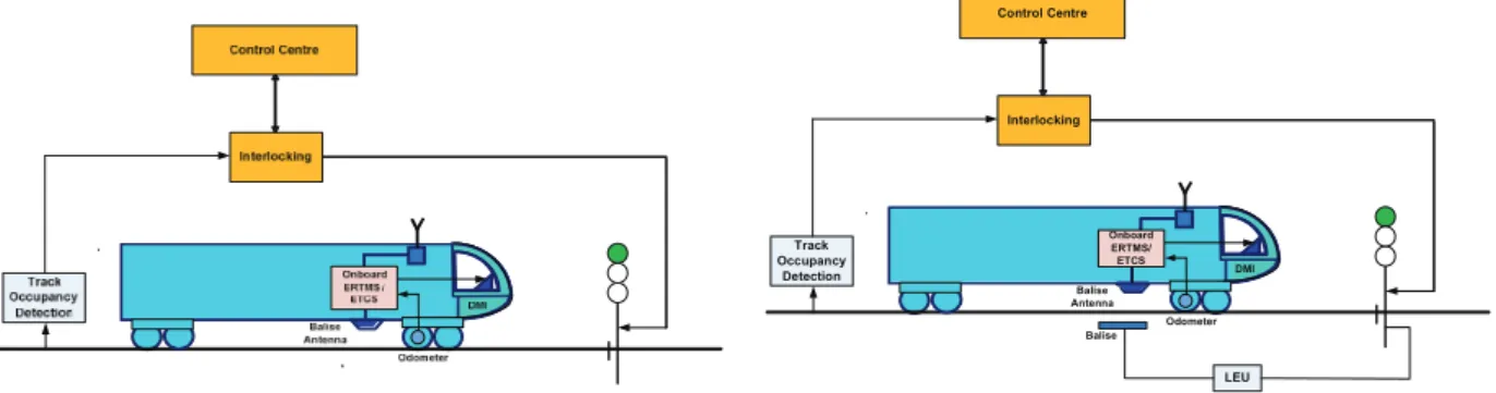
Level 0 (see Figure 3 below) represents the case where a train fitted with ERTMS/ETCS is operating on unfitted route (i.e. no ERTMS equipment are fitted on the trackside except Eurobalises for the level transitions) or on routes which are in commissioning, e.g. where trackside ERTMS/ETCS infrastructure may exist but has to be ignore. In level 0, the movement authority is provided by the lineside optical signals, the trainborne equipment only supervises the train with regard to the maximum speed and no supervisory information is displayed on the DMI except the train speed. The onboard equipment reads the Eurobalises to ensure that level transition can take place and also to supervise temporary speed restrictions.
Figure 3. ERTMS application level 0
B. ERTMS Specific Transmission Module (STM) Level
This level (see Figure 4 below) is used to allow an ETCS equipped train to run on routes that are fitted with national train protection systems. The information sent by the trackside national train protection system is processed by trainborne equipment called STM and this information is transformed by the STM in a format which is recognised by the onboard ERTMS/ETCS. In level STM, the need for lineside signals will depend on the implementation of the national train protection systems. This level can be used during the migration where the current national train protection systems can be integrated with the onboard ERTMS/ETCS with any further changes to the trackside infrastructure. The level of supervision provided by level STM depends on the national protection system.
Figure 4. ERTMS application level STM
C. ERTMS Level 1
In this level (see Figure 5 below) the communication between the trackside and train is accomplished using the Eurobalise. The Eurobalises which are installed on the track receive signalling data from the existing lineside signals via signal adapter and telegramme encoder (LEU) together with the route data to the train. The onboard ERTMS/ETCS uses this data to calculate the maximum speed and the braking curve. Eurobalises are installed near the main signal and due to the spot transmission used, the train has to travel over the Eurobalise in order to get a new movement authority. This means the train will have to slow down even if the lineside signal has changed to ‘Green’. This can be improved by using additional balises placed a further distance from the main signal in the train running direction.
&RQWUROVDQG,QGLFDWLRQV
%DOLVH
0RYHPHQW$XWKRULW\
(9&
'0,
2GRPHWHU
*60 55DGLR
7UDFN 2FFXSDQF\
'HWHFWLRQ
&RQWURO&HQWUH
,QWHUORFNLQJ
%DOLVH $QWHQQD
/(8
2QERDUG (5706 (7&6
In level 1 Euroloop or RIU (see Figures 6 and 7 below) can be used to send in advanced semi-continuous signalling information to the train regarding the next main signal in the train running direction. In the case of RIU the signalling information will be sent via the GSM-R network, therefore GSM-R coverage will be required even though this is not mandatory for application level 1.
Figure 6. ERTMS application level 1 using Euroloop
Figure 7. ERTMS application level 1 using Radio In-fill
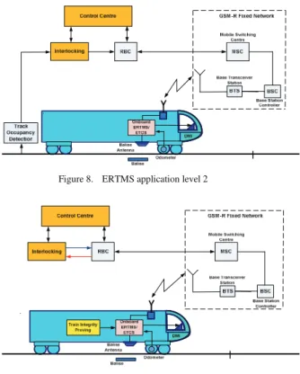
D. ERTMS Level 2
Compared to level 1, ERTMS level 2 (see Figure 8 below) does not require lineside signals. Information on the status of the track occupancy is sent by the interlocking to the RBC. Based on this information and the train position information sent regularly by onboard ERTMS/ETCS, the RBC generates the correct movement authorities for the different trains in the section. In level 2 the Eurobalises are used to transmit fixed data such as train location, gradient, speed limit etc.
E. ERTMS Level 3
This is a radio based train control system. In level 3 (see Figure 9 below) the lineside signals and the track occupancy detection are no longer required. The train location is determined by the RBC in co-operation with the train. In addition completeness of the train is checked by a technical devise on the train.
Figure 8. ERTMS application level 2
Figure 9. ERTMS application level 3
V. DYNAMIC SPEED MONITORING
The onboard ERTMS/ETCS assembly supervises the train speed against its position based on train’s traction and braking models. The traction model describes the time delay between ordering traction cut off and the actual cut off of the traction (see Figure 10 below).
Acceleration
Time Maximum Acceleration
Traction cut off delay
Figure 10. Traction model
Proportion of braking effort
Time 100%
Beginning of braking effort
Full brak ing effort 0%
Figure 11. Braking model – progressive application of brakes
Deceleration
Speed
(V1, A1) (V2, A2)
(V3, A3) (V4, A4)
Figure 12. Braking model with deceleration versus speed
train specific and these parameters are uploaded on the onboard ERTMS/ETCS as part of the train data.
Figure 13 below shows how the dynamic speed monitoring is carried out by the onboard ERTMS/ETCS assembly. The onboard ERTMS/ETCS assembly uses the train’s traction and braking models to calculate the braking curve to ensure that the train remains within the given speed and distance limits. Detailed description of the braking curve calculation is given in [12]. As indicated on Figure 13, the following speed limits are handled by the onboard ERTMS/ETCS assembly:
Sp
ee
d
,-, /-, " 7 9: 9:
Distance
Figure 13. Dynamic speed monitoring by the ERTMS/ETCS
1. Permitted speed – this is the speed that the driver is permitted to run under normal operational conditions and this speed is indicated to the driver (see Figure 1 above).
2. Warning Limit – when the train exceeds this limit a warning will be triggered allowing the drivers to avoid brake intervention. Once it is triggered, the speed warning remains active until the train speed is equal or below the permitted speed limit.
3. Service Brake – if the train speed exceeds this limit a service brake will be triggered. The service brake command will be revoked when the train speed is equal or below the permitted speed limit. The service brake is used as the first line of system intervention unless there is no interface with the service brake exists on the train or the service brake is not permitted by the national application.
4. Emergency Brake – if the train speed exceeds this limit, an emergency brake will triggered. Depending on the national application, an emergency brake command is only revoked when the train speed is equal or below the permitted speed limit or the train is brought to stand still. The emergency brake is usually used as the second line of system intervention except when the service brake is not available, the train has tripped (i.e. the train passed the End Of Authority (EOA)) or the due to release speed supervision (this is speed supervision in the area close to the EOA where the train is allowed to run with release speed to approach the EOA).
VI. ERTMS/ETCSLANGUAGE
In order to manage the complex functionality of the ERTMS/ETCS which covers the data exchange between the onboard and trackside ERTMS/ETCS assemblies via GSM-R radio, Eurobalise and Euroloop air gaps and the STM interface, ERTMS/ETCS language has been specified. The ERTMS/ETCS language is based on variables, packets, messages and telegrams [3].
The ERTMS/ETCS variables are used to encode single data values. A number of variables contain values which have to be assigned. Some of these values have to be unique to ensure that the system functions properly. A centralised handling of this assignment is therefore required (nationally or internationally, depending on the variable) [3]. The name of variables are unique and all variables have one of the following prefixes (see Table I below). Some of the ERTMS/ETCS variables together with their meaning are listed in Table II below.
TABLE I. PREFIXES USED FOR ERTMS/ETCSVARIABLES Prefix Variable Name Prefix Variable Name
A_ Acceleration NC_ Class number
D_ Distance NID_ Identity number
G_ Gradient Q_ Qualifier
L_ Length T_ Time
M_ Miscellaneous V_ Speed
TABLE II. EXAMPLES OF ERTMS/ETCSVARIABLES Variable Definition Meaning
D_DP Distance from
EoA to danger point
Distance from the end of a movement authority to the point beyond which a train shall not pass due to the potential of a collision.
L_Train Train length Length of train used for train speed supervision.
M_Level Current operating level
Level in which the train operates at any moment.
NC_TRAIN International train category to which the train belongs
Train categories used where e.g. speed profiles are not the same for different train categories.
NID_Operational Operational train running number
Train number under which a train operates.
Q_DIR Validity direction for transmitted data
Identifies for which running direction data in Eurobalise group or Euroloop is to be used.
X_TEXT Text string Text to be displayed to the driver
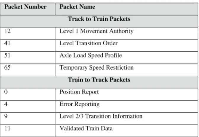
ERTMS/ETCS packets consist of multiple variables grouped into a single unit with a defined structure [3]. The packet is always consists of a packet header which is composed of a unique packet number, length of packet in bits, the information for which running direction the data is valid (when the packet is transmitted by the trackside ERTMS/ETCS assembly), optionally a distance scale and information section containing a defined set of variables. Table III shows examples of the track to train and train to track packets.
TABLE III. EXAMPLES OF ERTMS/ETCSPACKETS Packet Number Packet Name
Track to Train Packets
12 Level 1 Movement Authority 41 Level Transition Order 51 Axle Load Speed Profile 65 Temporary Speed Restriction
Train to Track Packets
0 Position Report
4 Error Reporting
9 Level 2/3 Transition Information 11 Validated Train Data
The ERTMS/ETCS messages are complete and consistent set of information transmitted from trackside ERTMS/ETCS assembly to onboard ERTMS/ETCS assembly or vice versa. A message includes user data (application level) and protocol data (depending on the transmission medium). A Eurobalise
message represents the information sent by a Eurobalise group (i.e. the message is composed of one or several telegrams, sorted by Eurobalise number in the group – telegram from Eurobalise number 1 first; each telegram is transmitted by a Eurobalise). A Eurobalise telegram contains one header and an identified and coherent set of Packets. Euroradio and Euroloop messages contain one header and an identified and coherent set of variables (if needed) and Packets [3]. Table IV shows examples of the ERTMS/ETCS Euroradio messages.
TABLE IV. EXAMPLES OF ERTMS/ETCSEURORADIO MESSAGES Message Identifier Message Name
Track to Train Radio Messages
3 Movement Authority
15 Conditional Emergency Stop
34 Track Ahead Free Request
38 Initiation of a communication session Train to Track Radio Messages
132 MA Request
137 Request to shorten MA is granted 138 Request to shorten MA is rejected 149 Track Ahead Free Granted
VII. CURRENT IMPLEMENTATION OF ERTMS IN
EUROPE AND WORLDWIDE
In most European countries, various projects for the implementation of ERTMS/ETCS on both trackside and trains exist at different stages. Table V below provides statistics for the deployment of ERTMS/ETCS in Europe in terms of track length and the number of trains fitted with ERTMS/ETCS system [6].
Originally the ERTMS has been design to be the unique signalling system in order to achieve interoperability on the European rail network. However recent years have seen a growing number of the countries where they are commissioning ERTMS projects. In fact the ERTMS investment outside Europe represents nearly 50% of the global ERTMS investment worldwide. Table VI below provides statistics for the deployment of ERTMS/ETCS outside Europe [6]. The data shown in the Tables V and VI includes the lines and trains which are in commercial operation as well as the signed ERTMS/ETCS contracts as per September 2010 [6].
VIII. CONCLUSION
This paper gave a brief introduction to the ERTMS which has been developed in the last two decades. The ERTMS is originally designed as a unique signalling system to achieve interoperability on the European rail network, however recent years have shown that the ERTMS becomes a global standard and it is being implemented in a growing number of countries worldwide. In addition to the interoperability, the ERTMS brings considerable benefits to railways worldwide, including:
between trains enabling up to 40% more capacity on currently existing infrastructure.
• The ERTMS allows for a maximum speed up to 500 km/h;
• The ERTMS can significantly increase reliability and punctuality, which are crucial for both passenger and freight transport;
• The use of a harmonised system makes it easier to install, maintain and manufacture and as a result makes the railway systems more competitive;
• When using ERTMS level 2 or level 3, trackside signalling is no longer required, therefore maintenance costs can be considerably reduced;
• The ERTMS can be purchased from different suppliers and this makes the supply market more competitive;
• The ERTMS improved the safety for passengers, employees and freight transport.
TABLE V. ERTMSINVESTMENT IN EUROPE Country Number of Vehicles Track Length (Km)
Austria 462 1004
Belgium 506 478
Bulgaria 130 1100
Croatia 0 130
Czech Republic 12 44
France 217 2600
Finland 0 100
Germany 461 816
Greece 136 1269.4
Hungary 23 343
Italy 198 1177
Luxemburg 186 450 Netherlands 298 630
Poland 8 622
Romania 0 822
Slovakia 0 106
Spain 533 4097
Sweden 62 2855
Switzerland 557 442
United Kingdom 27 217
Total 3816 19302.4
TABLE VI. ERTMSINVESTMENT OUTSIDE EUROPE Country Number
of Vehicles
Track Length (Km)
Algeria 0 852
China 290 5862 India 77 508
Kazakhstan 0 600
Libya 0 1700
Mexico 20 70
Morocco 68 160
New Zealand 0 350
Saudi Arabia 23 2849
South Korea 466 1678.4
Taiwan 811 1800
Turkey 110 1940
Total 1865 18369.4
ACKNOWLEDGMENT
The author would like to thank DeltaRail Group Limited for their permission to present this paper to the 1st International Conference on Energy, Power and Control (EPC-IQ01).
REFERENCES
[1] O. S. Nock “Railway Signalling” A.& C Black, London.
[2] F. Senesi, and E. Marzilli “European Train Control System – Development and Implementation in Italy” Published by CIFI – College of Italian Railway Engineers, First Edition July 2007. [3] UNISIG, “Subset-026 ERTMS/ETCS - Class 1 System Requirements
Specifications”, Issue 2.3.0 dated 24 February 2006 (www.era.europa.eu).
[4] Compendium on European Rail Traffic Management System (ERTMS), 1st
Edition, Edited by the international Union of Railways (UIC).
[5] The Association of the European Railway Industries (UNIFE) www.unife.org.
[6] ERTMS Deployment Statistcs: www.ertms.com/facts-and-figures/deployment-statistics.
[7] Electronic Communication Committee, ECC Decision (ECC/DEC/(02)05) of 5 July 2002 on the designation and availability of frequency bands for railway purposes in the 876-880 and 921-925 MHz bands.
[8] International Union Railways (UIC) www.uic.org.
[9] UNISIG, “Subset-037 ERTMS/ETCS - Class 1 Euroradio Functional Interface Specifications”, Issue 2.3.0 dated 14 October 2005 (www.era.europa.eu).
[10] Official Journal of the Euriopean Union “Technical Specification for Interoperability Relating to Control-Command and Signalling Subsystem of the Trans-European Conventional Rail System”, Commission Decision 2006/679/EC dated 28 March 2006.
[11] Official Journal of the Euriopean Union “Technical Specification for Interoperability Relating to Control-Command and Signalling Subsystem of the Trans-European High-Speed Rail System”, Commission Decision 2006/679/EC dated 21 February 2008.