r •
.
~. '! .
_
.
.,.
.
....
...
••
...
.
''I 1' • • ' iwf
.
'
..
• N ~ A A
.
·
~..
-...
~
.
'
4j
.i--- , . l.'
...
..
'
"
't
...
".
'P;UBLICAÇAO DA ABCM • ASSOCIAÇAO BRASILEIRA DE CIENCIAS
MECANICA~
.
..
...
":"',
V
O
L.
XIX • No. 4 • DECEMBER 1997
ISSN 01 00· 7386
..
.
.
-~
JOURNAL Of THE
~RAZ!LIA~
~OC!Etr
Of MECHANICAL
~C!
EN
CE~
I
RfVI~TA
~RA~IWR.~
D~ CIÊ~CIA~
MECÂNICA~
EDITOR: Leonardo Goldstein J~nior
UI ~I CAMP • FEM · DETF · C f'. 6m
1JOSJ -910 Çampinas SP
1?.1: 10191 2j9-3006 f a,- 1_019) 239-3722
EDITORES ASSOCIADOS: Aoenor de Toledo Fll!llry
rPT - lnsillulo de Pes~uisas Tecnoh\grcas
Oh·isac. ~e Mecânica e Eieuicidat::e - AgltJoamt:ni:J .j P. Sisif:1T1a:) de ·:::omr·;;.te C1dade Uni\lersitarla - C.P. 7!41
O 1 OF,4-97n S a~ Paute SP
r~ · :011) 268-22 11 flamat !>01 f;;x· :a11; 569 -:;:;~~
Angela Ourivio Nieckele
P::mliltCiã Unlversi:1<1::11? (;alêi!CéJ do Ric ~!? Janeuc
Deparlamentc de Eng e n~a r :a Mecáni ;~
R•Ja Marques de S3oj Vicente. 225 Gávea
22~53-90·3 Ric de Janeirl RJ
T~ !. . ([!21i 239-0719 Fa•· (021j 2~4-914R
Carlos Alberto Carrasco Allermani IJNICAMP · FfM -OE · C P. 612? 13083-510 GaT•J;mas Sf'
Tel.: 1019) 23S-8435 Fax: ror9; 239·3122 Paulo Eigi Miyagl
Universidade de S~o Paulo EscJI• Polilecr,;.:a
D f. ~ al tamenlc de E~-J~nha ri a M~can r.a - Mer.;,lrr.mca
A'.·enujíl Pr ~ f t ... 1fdlu M o 'ae~. 2:?:3'1 05508 - ~ 0\t $a-J Paulu SI'
Ter· (U11i Hl~ - ~~80 Fax 1011 ; ô18 · S 4 / 1 /S 1J · 1H~E
Waller L Weingaertner
Universida·je Federal ce SoniJ Gatanna
De~ - a tamen l o de E ~ çenha ri a Mecânka · l ab·ocala"o cc MecJn;ca dt Pr~~ r s ac
Gampus Un ·, ~ r s rt á: i o Tr Made - C P 47G
88-J4·3 902 F Olta nó poh~ SC
lei . [·J4R) m-9.195!234-5277 Fax (0431 2:14· t51S CORPO EDITORIAL :
"-'c" ~e FaroOrlandu (PUC ·RJI
.~nto :t l::- FtctiK•so:e fo rle~ (Unf.)
f•.rmanjo Alberlmi Jr. (UF SC'r Atarr R·OS Neto (II-IPE; , Benedilo Mcracs P~rQue ro (EESC·USPj Caie Mari:l Costa (EMBRACOi Cartns Alberto de .~lm~ija (PUC-PJf
G ~ rl u S Alberto M3rlin !liFSCi Clov.s RamrrJfldo Malisk~ (UFSC'r ET.anJel Hocha Woiski IUiifSP-FEIS)
Ftancrsco Emliio Baéclrc i'lhlrc iiPT-$Pl F:onci&:c JJ;t SimOes (UFPbj · 3cnes•o JJsé Mencn iEfEI)
t~l a l : s ln ~:l Webt!r (UNICAMP:r
He nrr qu ~ Ro1~ nleld !fESC LISP) Jair Carros Outra : UfSCi João ~. I mo llerz de Jornada (UfPGol José Jcac de EsprnjJia (UFSC 1 Jurancir ~l i ll YanaQihala (EP USPj LiriJ Scrraercr IUFPGS) Lr.uri•;al Bo~ hs (UFSC) l.rns C•dus s~nC ( V~I ~c~s til Ai
Milr<ro livrijrrr (UFMG) Moyses l.t~ deluk (C(lf'r-E-ltfRJr NisroJ de Car•;alho Lobo 8rum iGOf>PE ·UfRJl Ni•1aldo lerr.os Cupini •:\JNICAMPi PaulO Afonso de Chvcha So·;iCIO (IT/1) R•l9étr•.l Martins Saldanha da Gama (LNC:' 'Jat.jer Sl~ ll 11 Jr (UFU)
REVISTA FINANCIADA COM RECURSOS DO
Programa de Apoio
a
Publicações Científicas
RBCM -J. of the Braz. Soc .. Mechanlcal Sclences
Vol XIX· No4 • 1997 • pp. 445457
ISSN 0100·7386 Printed in Brazil
Steady, Spatially-Periodic Fully-Developed
Turbulent Flow in lnterrupted-Piate Channels
Simone Sebben
Universidade Federal do Aio Grande do Sul Escola de Engenhatia
Departamento de Engenharia Química 90.040-040 Porto Alegre, RS Brasíl
Abstract
This pape r presents numerical results for steady, spatial/y-periodic, two-dimensional, fully-developed turbu/ent flows in interrnpted·suiface passages. The geometry of interest consists of an array o.f interrupted piares. in an in·line
arrangement, p/aced paral/el wilh the main flow dlrectiorr. Such a configuratiorr can be regarded as a two·
dimmsional idealizaJio11 of rhe cores of some offset~fin compact heat exchangers. The peifonnance of severa/ /aw·
Reynolds nwnber, two-equation linear eddy-viscosity models of turbulence is discussed in the corrtext of a time·
averaged formulation. Sinwlarions were carried oul for a range of Reynolds numbers and one value of the p/ate tltickness. Numt'rical prediction.r of the friction factor and skin jrictio11 coeffi.cient along the plates are compared
wi!h avai/ablt' experimellta./ results.
Keywords: Turbulence, Periodic Flows, Contrai- Volume Method. Heat Exchn.11gers.
lntroduction
Flow passages with spatially-periodic interruptions are com.monly eocountered in heat transfer equipmem. sucb as compact beat exchangers (Shah, 198 I ; Kays and London, 1984 ). Compact beat exchangers are used in lhe cbemical. material processing, and power-generation industries. as well as in automobiles and aircrafts. The interruptions in lhe flow passages are intended to produce enhanced heat transfer rates, but lhey also cause higber pressure drops than lhosc encountered in uninterrupted configw·arions. Thus, the design of such heat exchangers involves an optimization problem in which the objective is to obtain the maximum heat transfer r.i!e between tbe hot and cold flu.ids, for fixed values of the associated pwnping power. Olher examples of fluld flow in interrupted passages are provided by coollng arrangements for elecu·onic equipment (Kakaç, et al. , 1993; Kel.kar et ai.. 1993; Patankar. 1993; Wang et ai .. 1997). Effective cooling of circuit boards in electrOnic devices is crucial to ensure reliabilir.y of sue h systems.
The understanding of lhe fluid flow and beat transfer pbenomena that occurs in compact heat excbangers has motivated rescarchers for many years. Experimental data on overall heat transfer coefficients and pressure drops obtained frorn tests on either actual or large-scale rnodels of heat
exchanger~ that incorporate interrupted passages bave been reported in lhe literature, examples include tbe works of Wíeúng (1975), Sbab (1981 ), and Kays and London ( 1984 ). Althougb this data can be used directly in the design of interrupted-surface heat exchangers. it cannot be used as definitive checks on numerical predictions because of the Jack of necessary local details. Many oumerical and experimental studies of t1uid flow and beat transfer in simptitied periodic geometries have also been reported in the literature. Most of the investigations were conce.med with ~teady-state laminar flows (Patankar et ai., 1977: Patankar and Prak.ash, 1981 ; Sebben and Baliga. 1996a; Fowler ct al., 1997). However, typical ranges of the Reynolds number in compact heat exchangers extend from a laminar flow regime to a low Reynolds number turbulent flow regime (Kays and London. 1984).
Over the last decade. experimental and numerical studies of statistically steady. spatially-periodic turbulent flows bave also appeared in the literature. Exarnples include the works of McBrien and Baliga ( 1988). McBrien (1989), Faghri and Asako (1990). and Kim and Anand (1994). The numerical solution of the problem in conjunction wilh the time-averaged fonn of the goveming equations bas become a common practice in tbese type of turbulent tlows, mainly due to the bigh computational effort required by unsteady formulations. For rhis reason, relatively few numerical i.nvestigations of unsteady turbulent flows in intcrrupted-surface passages have been reported. Some exarnples are the works of Ciofalo and Collins (1992), Ciofalo et al. (1996). and Sebben an4 Baliga (1996b).
The present paper de~cribes lhe analysís and results for statisticaliy stcady , spatially-periodi c, fully-developed turbulent flows in lhe interrupted-plate rectangular duct illustrated in Fig. I (a).
446 J. of the Braz. Soo. Mechanlcal Soiences • Vol. 19, December 1997 dimensional numerical simuJations were perfonned using seven low-Reynolds numbers, two-equation, linear eddy-viscosity models of turbulence (EVMs). The intention in this work was to compare the uumerical predictious of the frictioo factor and skln frictíon coefficient to the availablc experimental data from McBrien (1989), and discuss the relative perfonnance of severa! low-Reynolds number EVMs ín lhe context of a steady Reynolds time-averaged formuJatiou. A concise descriptiou of lhe rationale for the cboice of eddy-víscosity based, low-Reynolds number time-averaged models is also discussed. The work reported here is part of an effort of parallel ínvestigations of unsteady, self-sustained oscillatory tlows in ínterrupted surfaces of lhe type encountered in compact heat exchangers.
Mathematical Formulation
The problem of interest involves statistically steady, two-dimensional, spatially-periodic fully-developed turbulent tlows in rectangular interrupted-plate ducts akin to that showo in Fig. l(a). Such ducts aro characterizod by geometrically identical and spatially-periodic modules as illustrated in the cross-sectional view presented in Fig. l(b). ln this figure, a spatially-periodjc geometric module is the domain indicated as ABCDA. Attention is focused in the region ABCDA because, with the assumptioo of statistically steady flows. the channel centerline becomes a symmetry tine and. th.erefore, the calculation domain can be limited to one-balf of the channel height (region ABCDA). It is to be noted that effects of vortex shedding have not been considered in the pre!)ent investigation, even though vortex shedding from the plates can occur for some combínations of the Reynolds number and ge.ometrical parameters of the duct. This assumption implies that the frequencies of vortex shedding are treated in the sarne manner as flow turbulence, and are time-averaged to allow steady time-mean flows. As previously mentioned, tbis consideration is often made to reduce lhe computational costs involved wilh au unsteady approach to the problem. It is also assumed that the fluid is Newtonian, incompressible, and with constant tbermopbysical properties. This assumption is commonly ínvoked in design calculations for plate-fin heat exchangers. with the fluid pr()perties values based on mean bulk temperature.
• 2o
A
B~
~
4
E-- ·
2H (b). . I
s
I Iex
I I0'
IC•
IFig. 1 (a) Rectangular lnterrupted·Piate Ouctj and (b) Cros&-Sectlon Vlew, Assoclated Nomenclature and a Representatlve Geometrlc Module ABCDA
S. Sebben: Steady, Spatially-Periodio Fully-Developed Turbulent Flow ... 447
plane (Sparrow et al., 1977; Sparrow and Hajiloo, 1 980; Loehrke and Lane, 1982). ln the fully-dcveloped regime, tbe clistríbutions of tbe velocity components repeat ideutically in successjve geometrical modules (Sparrow et ai., 1977). With reference to Fig. l(b), the periodic behavior of the time-averaged velocity componentl> can be expressed as:
ui ( x, y )=uj( x+( L+s ).y J=u;f :c+2( L+s ),y )= ... (I)
where (L+s) is the length of one module.
A procedure for the solution of the flow in a single module in t.he fully developed region has been dcscribed by Pat.ankar et al . ( 1977). As explained by Pat.an.k.ar et al. (1977). the reduced pressure, p. can · be expresse.d as a linear combination of an overa!J pressure drop. which drive.~ the fl.ow in lhe streamwise direction. and a pressure P which is related to lhe details of the local motions in lhe geometric module. Thus, Lhe reduced pressure can be expressed as follows:
p( x,y )=-f3x+ P( x,y) (2)
where Lhe tenn
f3
is a uniform value for Lhe entire periodic region. and is responsible for tbe overall mass flow raie through the module. ln tlte present work,f3
is treated as an adjustable paramcter so as to obtain a desired, or specitied Reynolds number in the problem. The pressure P behaves in a periodic manner from module to module. Ak:in to the velocity fielcl the period.ic condition for P(x.y) can be wrineu as follows:P{ :c,y )= P( x+( l.+s ),y )= P( x+2( L+s).y )= ...
(3)
Using Eq. (2). the time-averaged continuity and momenrum equations can be written as:
(4)
aui
ps:-
Jp
d ( du; -,-,
J
puj-= u;1
- - + - .
j l - - puiujdxj
dx;
éf.xjJx
1 (5)where 8,1 is the Kronecker delta, and the correlation pu[uj is interpreted as the turbulent stresses, commonly referred to as the Reynolds stresses. They are unknown elements in the time-averaged equations and need to be modeled in order to "close" the set of equations.
ln thi~ work, six variations of lhe low-Reynolds number K
-e
model were assessed to predict lhe flows of interest: The Joues and Launder (1973) and lhe Launder and Sharma (1974) models, which will be denoted as JL and LS, respectively; lhe Jones and Launder (1973) and Launder and Shruma (1974) models with a modification proposed by Hanjatic and Launder (1980). which will be denoted as JLH and LSH, respeclively; and lhe Launder and Kato (1993) model with the closure cocfficients proposed by Jones and Launder (1973) and Launder and Sharma (1974), which will be denoted as LKJ and LKS, respectively. The low-Reynolds number 11.-w
of Wilcox (1988, 1993). WL, was alsoa~sessed in the present investigation.
448 J. or the Braz. Soe. Mechanical Sciences- Vol. 19, December 1997
EVM!> with wall functions in lhe modeling of such flows. Wilh regard to lhe different low-Reynolds number EVMs tested. the modificatioos included io lhe JLH and LSH models were proposed by Hanjalic and Launder ( 1980) in order to improve lhe predictions obtained with the JL and LS models in
flow~ wilh adverse pressure gradients. The model of Launder and Kato (1993). inítia.IJy proposed for penodic unsteady flows witb vortex shedding. is testcd here to evaluate its performance in a steady formulation of lhe govcrning equations.
The úme-averaged equations for the~e various low-Reynolds number
"- e
models can be writtenas follows:
(6)
iJc
iJ [(
p, )ac]
1: 2 2pp, [a
(<li, )]
2pu
1- = - .
J J + - -+ PC' Czrh P +
-iJx,
ax,
araxj
kp
axj ax.
(7)lt is to bc noted that Eq. (7) is written in Lerms nf 'é . rather tban the dissipation E • The dissipation,
e,
is related to lhe quanrity i: by E = E:'u + 1:', wheree,
is the ftnite vaJueof
e
at
the wall. The practice of writing lhe rate of dissipation of k. and its governing equation in terms ofe .
rather Lhan , has tJ1e computational advantage Lhatê
becomes zero at a solid wall. ln thc ubove equations. the~rbulent viscosit>:· )J 1 , is giveo by J11 ":" J
v."v.Pk"
f_ê,
and the production tenn of tlleE
equation,Pe,
IS gJVen by Pe
=J,
[C,ePd l-8ij
)+CJe Yk()ij /(eI k).
Ovcrall. the six Jc
- e
models used hcrc. named: JL. LS. JLH. LSH. LKJ. nnd LKS. containtive clo:oure coefficients that nriginated from the high-Reynolds number version, plus other dumping
Table 1 Constants from the High-Reynolds k-
e
ModelG c C/c Cu
_ _ 0:_.0"'9'--_ _ 1.0 1.3 - - -,.-44---.,.-1 . ..,..
92::-l'unctions due to low-Reynolds oumber modifications. A summary of lhese variou.~ closure coefficients
aud dumping functions is given in Tables 1 and 2, respectively. Tbe cxprcssion for lhe rurbulence production tcrrn.
Pk ,
for these various mudeis is given in Table 2.Table 2 Constants and Expresslons Used in the Low-Reynolds k -
e
Modelsk
- e
/y j,h
C Jc pkJl
___l.L_ / -Jt!· R.f 1.44(
~
i:-
)~ j
e'+o.ozh,
)J., ~ +
ãr;
I r
LS -11
1-Jt! Rt{ 1.44
(~
~)~
e (1<{1112/Wr ~1
)J,
'dt7 +~
~
JLH
--=L}_ 1- .Jt- R•f 4.44Pt(~+~)*
e , .. o.ou1,,
LSH
-,_.!._i1- 3 e· R•{ 4.44
11t
(~+i'-)
a..'
e ( I•O.m Rtt ~1j I
dt,"
LKJ
-=1..}_ 1-Jt!· R<'f 1.44t(~+itr
1(~-~r
e '+{}oz~~~r
)J.,
LKS -J.4 I 3t!· Rt! 1 .44
1( ~ + ~r
t(~-
: ~ r
S. Sebben: Steady, Spatlady-Periodk: Fully·Developed Turbulent Flow ...
The time-averaged equations for lhe low-Reynolds number 1<
- w
model are now presented.Following Wilcoll ( 1993), lhey can be written as:
where lhe specific diss ipation rate,
w,
is dcfined as:E
W
=-k
(8)
(9)
The turbulent viscosity, J11 .is given by J.J, =cjtp/.1
w.
and P, is modeled as in lhe JL, LS,JLH.
andLSH models. The values of lhe fi ve closure coetflcie n L~ of lhe k-m modcl are prese nted in Table 3.
Table 3 Constants ln the k -w Model
0.09 2.0 2.0 519 516
Wilh relerence to Fig. I (b), lhe boundary condi tions for lhe problem are lhe folJowing: Period ic conditioos across AD and BC: v = O and symmetry condition.s for u. k,
i .
and w along line AB; and11 =I'= k
=E
=0 at the surfaces ofsolid boundaries. For lhe K-w model. the boundary condition on wat the soüd boundaries is given by (Wilcox. 1988):
6( 11/P)
ú) 2
C2wll
(lO)
where Ll represent~ lhe physical normal distance to lhe solid surface of the first adjacent w grid-poinl. Wilcox ( 1988) recommends lhat lhe location of lhe rnesh poiot.s closest to lhe solid surfaces be chosen so t:hat ..1+ ~ 1 : and lhat adjacent to each solid surface. atleast tive mesh points along each wall· normal grid line lie within ..1+ S 2.5. The quanti ty Ll+ represents a dimensionless normal di stance from the wall, defined as: .1+ =p u ~ L\ I 11 .
With reference to lhe notati on in Fig. l(b), the computations were performed for lhe following nondirnensional geomctricaJ parameters:
8
-=0.11.
H
L
s
-=177 -;;; /76
H ' H (l i )
Tbe resuJ ts are presented in tenns of nondirnen1ljonal quantities: lhe Reynolds oumber, Re. lhe fri cti on factor,ff. and the sk.in friction coefficient on the surface of lhe plate, •..,. These quantities are defined us:
Re= pU(2U
J
11
ff
=
{J(2UJ '
o.spu
1•
r,..,
-r,.,-
- 2 0.5pUwhere V is the tirne-rnean streamwise averagc vclocity.
( 12)
Four Reynolds numbers wcrc considered: Re
=
4997, 10980, 16930, and 27840. These values of lhe450 J. olthe Braz. Soe. Mechanical Sclences • Vol. 19, December 1997
Computational Details
The computalional domain was confined to lhe region den01ed by ABDCA i.n Fig. I (b). 11 was di scretiz.ed using staggered grids for lhe velocity components and pressure, as discussed by Patankar ( 1980). A~ çan be $een in Fig. I (b), lhe calculation doma.in includes a solid region (plate), as well as a Ouid Oow region. A convenient melhod to treat internal Oow blockages (plates) has been discussed by Patankar ( 1980): lt consists of setting Lhe lluid viscosity equalto a very large number; in addition, in Lhe present computations. the coefficients of the discrerized equations were overwritten so as to obtain identicaJiy zero for lhe dependent vuri<1bles (u, v, P, k,
"E )
in lhe bJocked zones. The coefficienL~ of the d.iscretized cquation form
were sel soas to satisfy lhe boundury condition given by Eq. (10) dose 10 the solid s urfaces.Ali compulations were performed with nonuniform grids. When using low -Reynolds number
turbulence models. fine grids are needed in arder to adequately resolve the very stee p gradients of lhe dependent variables througb the viscous sublayer. aJI lhe way to lhe wall. Furlhermore. in order to place tbe ftrSt gnd pomt adjaceOl to a solid boundary within the desirable normal nondimensional distance of
~ + <;,J. the corresponding required pbysical distance, L1, can be very smaJJ, specially for higher
Reynold~ numbers. This restriction made lhe use of uniform grids probibitive.
The momentum equation, Eq. (5). was discretized using tbe QUlCK scheme ~f Leonard (1979).
The SIMPLEC algorit:lun of Van Doonnaal and Railhby (1984) was used to solve Lhe discretized
momentum and pressure correction equations. The tnmsport equations for lhe turbulent quantities k,
E .
and
w
were di scretized using the hybrid schcme (Patankar, 1980). The use of higher arder schemes. such as lhe QUICK scheme of Leonard ( 1979), in lhe discrctized equations of k.i,
andw
can produce negative coefficients. which in tum, can lead to negative effectivc turbulent transport coefficieots and numerical instability (Lien and Leschziner, 1994). Such negative values can appear particularly in regions wbere tbe actual (positive) k andE
values are close to zero. ln most circumstances, however. lhe turbulent transport equations are dominated by thcir source terms. Tbus. the arder of lhe schcme used in lhe discretizatíon of the convective terms in these equations is of relati vely linle imponance, provided it is dane coosistently (Lien and Lescbziner. 1994). Based on the aforemeotioned JUstifications, in this work, lhe QUICK scheme wa.s used for lhe discret.ization of lhe u and v equations, while tbe bybrid scbeme wa~ used for lhe k,'l
and w equations.Four line-by-linc itcrative algoritbms were used lo solve tbe oominally linear and dcroupled set of equations: the tridiagonal and pentadiagonal JlUitrix algorithms (TOMA and PDMA), and lhe cyclic tridiagonal aod pentad.iagonal matrix algoril.hm (CTDMA and CPDMA). The cyclic algorithms are required for !ines of nodes aJong which the periodic boundary conditions apply (AD and BC). Detailed descriptions of these and related algorithms are available in the work of Sebben and Baliga (1995), for cxample. Genenllized block-correction procedures (Scttari and Aziz. 1973) were used for the velocity components and pressure correction, in order to speed up lhe coovcrgence of lhe Line-by-line algorithms. The block-correctíon procedure W!l!. not used in the iterative solution of the discrctized
equatioo~ for k,
'l.
andm.
as it did not improve lhe overaJJ rate of convergence of these equations. To SUU1 lhe calculat ions. an initiaJ value off3
had to be specifíed. Tbe experimental values of tbe Reynolds nurnbcr and friction factor rcsults of McBrien (1989) were used to obtaio init.iaJ values off3
using Eq. ( l 2). For each run.{3
was adju~tcd at each iteralion of the overall solution procedure, soa~ to rnaintain lhe Reynold~ number at lhe desired value. The procedure for adjustingf3
wa~ IJ1e sarne as that proposed by Kelkar et ai. ( 1993). Pollowing the recornmendations of Kelkar el ai. ( 1993), lhe value off3
at the e nd of each SIMPLEC iteration, was modified in lhe following manner:where U is the averaged velocity tbat will generate lhe de~ired Reynolds number,
lJ"
is the averagc velocity of the lust available flow field, corresponding lo lhe pre&Sure gradient {3'' • and the eltp<lnenta
is an undcrrelaxation factor set equal to 0.9. lu the end of each iteralion, after adjusting/3,
lhe velocity field was adjusted as foU ows:S. Sebben: Steady. Spatially-Perlodic Fulty-Developed Turf>ulent Flow ... 451
Convergence was considered to be achieved wben lhe sum of lhe absolute values of lhe normalized
residues of lhe discretized equations for
u. v,
k.1.
andw
were less than 10-1. Tbe underrelaxation factors for k.i ,
andw
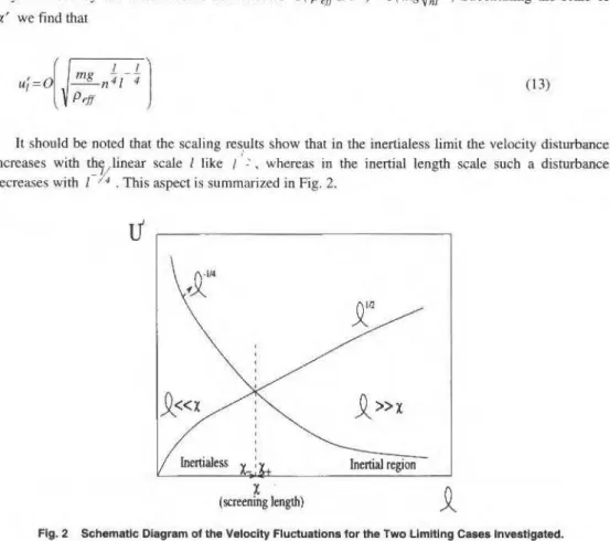
were set equal to 0.9. while for u and v tbey were calculatcd at eacb iteration using.lhe following expression:(13)
where ij
are
nodal índices lhat cover the entire solution domai n; anh are the coefficients of the discretized equations: Sp is part of the linearized source term (as discussed by Patankar ( 1980)): andáV is Lhe volume of lhe control volume.
Results and Oiscussion
Validation of Computations
The finite volume method (FYM) code was subjected to numerous verification tests. in accordance wilh well-estabHshed guidelines, sucb
as
those cliscussed by Patankar (I 980). The capabilities of the code to solve spatially-pcriodic, fully-developed tlows is well doc umented in Sebbcn and Baliga (1996a). Steady, fully-developed turbulent Oow ina
two-dimensional straight chan nel was the problem considered to test lhe implementation, in lhe computer code, of tbe low-Reynolds nu mber versions of the k -E and k-w
models (lhe ILH, LSH, and WL models were te~ted). Steady, fully-developed flows in straight channels can be predicted by solvinga
one-dimensional formulation. However, for testing purposes, two-dimensional simulations were carried out to cbeck the two-dimensional implemenUHions of lhe aforementioned rurbulence models. ln lhe simulations, periodic condiúons wereimposed at lhe inlet and outlet flow boundaries. The results of lhese cnmputations were cbecked against
lhe Prandtl-Jones correlation (Jones, 1976) which gives lhe friction factor
as
a funcúon of the Reynolds number. Calculations for Reynolds numbcrs in thc extreme range of lhe Re value~ investigated in lhe interrupted-plate cbannel flow problem were considered. The friction factor results. particularly lhose obtained with lhe ILH model, agreed well with lhe corresponding values yieldcd by lhe Prandti-Jones correlation. Specifically for Lhe JLH model. the v alues were wilhin 2% of the Prandti-Jones correlation values. Detailed description of lhese results can be found in Sebben (1996).The solution of tbe aforementioned tcst problems allowed an effective evaluation of the vaHdity and
capabilities of lhe proposed FVM computer code for predicting spatiall y-periodic, fully-developed turbu lent tlows in interrupted-plate geometries.
Grid lndependence Study
Fricúon factor results obtaincd witb lWO nonunifonn grids are presented in Table 4 for all seven
turbulcnce models used in this work. The number of control volumes in lhe two nonuniforrn grids were
Grid I = 72x.l 00 and Grid 2 = 144x200, in the x and y directions, respectively. A larger number of grid points were concentrated near lhe solid walls and plate surfaces. A typical grid pattem is illustratcd in Fig. 2.
452 J. of the Braz. Soe. Mechanlcal Sciences • Vol. 19, Deoember 1997
From Table 4 it
can
be observed tbat the friction factor values calculated with the 1LH model show the smaUest differeoces in the results obtained witb the two grids considered: These differences rangefrom 0.25% to 4.5% forRe: 4997 and 27840, respectively. On the other band, tbe rcsults obtained with
the WL model sbow Lhe biggest differences in the values obtained with the two grids: Tbese differences
range from 13% to 25% forRe= 4997 and 27840, respecti vely. For the other models, these differences
in the friction factor results are ali within
10%.
It is also noted that theJL,
JLH, and LKJ models arele.~s sensitive to grid refmement than the LS. LSH. and LKS models, respecrively. The only difference between the JL and LS models is in Lheir ex.pression for the damping function. j~. This statement also applies to the JLH and LSH models, and to the LKJ and LKS models. As expected. for each model, the difference between the results obtained with Lhe two grids increases as the Reynolds number increases. This is because with any given grid. ali the Reynolds number increases. the gradients that occur near the solid regions are steeper.
Table 4 Friction Factor Values Obtained With Seven Turbulence Models: Grid 1 = 72x100 and Grid 2 = 144x200 Control Volumes
ffx1rf
R
e
GrldJL
LS
JLH
LSH
LKJ
LKS
WL
4997 8.309 8.240 7.144 6673 7.460 7,078 8.836 2 8.127 7.691 7.126 6.462 7.338 6.776 10.13 10980 8.995 8.924 6693 6.449 7.660 7.590 6.729 2 8.482 6.258 6.479 6.095 7.281 7.065 8.360 16930 9.121 9.005 6.588 6.407 7.732 7.638 6.246 2 8.498 6.261 6.327 6.004 7.401 7.222 7.954 27840 9.090 8.971 6.407 6.272 7.688 7.607 5.758 2 8.401 8.183 6.129 5.857 7.333 7.127 7.666
ln general. the number of grid poi.nts used in the y-direction, in botb grids, was large enou~b to guarantee that the mesh points closest to the solid wall and plate surfaces were below the .1 =I
values, for aU models and Reynolds oumbers smdied. In the x-direction. however, this condition was satisfied only in the lower range of Reynolds numbcr. For
Re
=
27840 and Grid 2, the normal distance of the grid points closest to the pi ates in the streamwise direction yielded .1-.$ 2, raiher than the desired.1+ .$I .
Friction Factor Results
Plots of tbe .ff versus Re resuJL~ . along witb the experimental data of McBrien ('1989). are shown in Figs. 3(a) to (g). ln these figures, tbe filled circles (• ) represcnt the experimental data of McBrien ( 1989), the triangles (ô) represent the numerical results obtained with Grid I, and Lhe squares ( , ) rep1·esem the oumerical results calculated with Grid 2.
The plots ln Figs. 3(a) to (f) show that tbe resuJts obialned wilh the JL, LS, JLH, LSH. LKJ, and LKS models are quite unsatisfactory, even wíth thc finer grid (denoted by ). The absolutc values of the di fference between the cornputed results and the experimental results of McBrien ( 1989) can be as
high a~ 30%. Furthermore, Lhe experimental resuHs show Lhat.ffvalues decrease appreciably with Re, in
the range of parameters studied. Howcver, the.ffvalues obtained with the JL, LS, LKJ. and LKS models
increase witb R e, albeit only slightly. Tbe
ff
values obtained with the JLH and LSH model s sbow aS. Sebben: Sleady. Spatlally-Periodic Fully-Oeveloped Turbulent Flow ... 453
JL Model LS Model
0.10
•
010•
ff ff
"
a
c,.
~ ~
0.08
••
a) o.08 o b)•
•
•
•••
••
0.06 0.06
10'
R
e tO'R
eJLH Model LSH Moc.lel
0.10
•
0.10•
ff ff
0.08
••
c) 0.08• •
d)o
•
•
•
a a
•
ft•
e
A..
!•0.05 0.05 o o
ter
R
e 10'R
eLKJ Modal LKS Model
0.10
•
0.10•
ff ff
0.08 • ! A
.
e}
0.08•
"
f)..
1.1 D 11 I)
A o
•
•
o•
••
••
0.05 0.06
10
R
e 10'R
eo WL Model 0.10
•
ff
0.08
.
"
•
o g)A
•
•
"
••
0.0610
R
eAg. 3 Comparlson Between the Experimental Frlctlon Factors of McBrlen (1989) and the Numerlcal V alues Obtalned wlth Seven Olfterent Turbulence Models
Thc effect of usiug lhe Hanjalic and Launder ( 1980) modification is quite significant, as can be observed with refercncc to Figs. 3(a) and (c). and (b) and (d). The JLH and LSii friction factor results are lower than the corresponding values obtained with tl1e JL and LS models. Tbe effect of tlus modificatiou is more prominent at higher values of R e. with a difference of as much as 40% in the
ff
values at corresponding Reynolds numbers.The results obtained with the WL model (Fig. 3(g)) show lhe best agreement with the experimental resuJts, both qualitatively (trend) and quantitatively. However, the differences between tbe
./J
values obtaincd witll Grid I (~) and Grid 2 ( ) are ratller large, relative t.o tllese grid-related differences in the results obtained witll the otllcr turbulence models. Furthermore, it was found that the WL model results are very sensitive to tlle placement of tlle grid points adjacent to tlle soHd boundaries. Thís statementapplies cveo when Lhe recommendations of Wilcox (1988) (namely. normal distance from a solid
boundary of the tirst adjacent grid poínt sbould give ,;1+ <I, and the next four nodes should satisfy d+ < :!.5 are met. lt should also be noted tllat in order to meet these recommendations. very fine grids are required in regiam; adjacent to solid boundaries. As mentioned before, for tlle case of Re = 27840,
I
tlle recommendation of the fírst grid point wichin á+ < I was not satisfied in the streamwise direction even witb the finer grid (Grid 2).
I
Streamline Plots
454 J of lhe Braz. Soe. Mechanícal Sctences- Vol. 19, December 1997
Grid 2. ln Figure 4, a very small recircuJation wne is observed al lhe plaLe leading edge a.~ the flow impinges the plate. Downstream of lhe plate ll'11iling edge a recirculation z.one of approrunately
5o
in lenglh i~ also observed. The streamJines in lhe core region of the channel are more or less al igned with Lhe mean flow direc tion.[ (r' ~
""
--
-Fig. 4 Slreamllne Plots forRe c 10980 Obtalned wllh the WL Model
Skin Friction Coefticlent Oistributions
_ ,
For
R e=I 0980.
disllibulions of sk.in-friction coefficieot,r:
:or"
I 05 pU- . on the sulfaceof
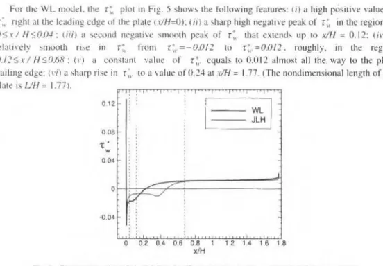
Lheplate are presented in Fig. 5. ResulLs obtained wi th the JLH model and Lhe WL mode l are prescn t.cd in this figure. lt is seen in Fig. 5 thaL up to x/H=0.68, Lhe rwo models behavc quite differenll y. with lhe JLH model given rise to a much longer separation zone at the pi aLe lcuding edge. Aftcr xiJ-1=0.6fl. there
i~ a pretly good agreemcm bcLween the result.s obtained wilh the two models.
For thc WL 1111K.id. thc r : piO! in Fig. 5 -;how' the following fenture'>: ( 1) a high po!.ILÍ\ e ,·alue o
r "
nght :11 tht> leading cdge o l th<' plate ( r/H:()l: ( iil a '>harp high oegati\'e peak ofr ..
in thc regiono
U S ' I H '(;, 0.0-1 : U1i) a '>CCl'l1d negative smnoth peuk of ( ,. t.hat extencls up Lo x/H = 0. 12: (il·) ; rt'latively :.mooth ri"'~ in r ~ , from r,..=- U.U/2 to r ~ , = 0.012. roughl y, in lhe regim
IJ./2 ~ r I H 5 0.68 : (r) u ~.:onstant v alue (lf r:,. equals to 0.0 12 11 hnost ali the. wuy to thc p!at1 trailing edge: 1 1·i')
a
'>harp rise
in r ~ ,. toa
\alueoi'
0 . ~4 at .dH = 1.77. (Thc no n dimen .~ional l cng t h of Lh< plute i ~ UH = 1.771.0 12
0 .08
"C'
w
o
04·0 .04
o
0.2 0 .4 0 .6 0.8x1H
~ l
I
1.2 1.4 1 6 1 8
Fig. 5 Disb1butlon ol l he Skln-Frictlon CoeHlclent on the Surlace of the Piate for Re
=
10980Thc aforementioncd feam res of the skin fricúon coefficient dístribution obtained witb the WL model compare ralher well wiLh the r ~, dístribution that can be inrerred from the plate-surface oil-flow
S. Sebben: Steady, Spatially-Perlodic Fully·Developed Turbulenl Aow ... 4S5
predicted a constanl v alue of
r7,.
almost ali the way 10 the eod of lhe plate. A photograph of tbe surface streamline panem obrained by McBrien (1989) for the sarne interrupted-plate duct andRe
= 10980 is given in Fig. 6.Ag. 6 Plate-Surface Streamllne f orRe= 10980. Maln Flow Dlrection Is From top to Bottom of lhe Plcture: Experimental Resulta of McBrlen (1989).
Experimentally, lhe flow undcrgoes strong accelerations atlhe plate trailing edge region, which are cause.d by an oscillating wak.e and possible vortex shedding. Thls flow acceleration gives rise to the smootb oil-flow pattem seen in Fig. 6 in the vicinity of the ITailing edge of the plate. ln the presem steady-statc simulatioos, however, lhere are no wake oscillations, or vortex shedding, thus the flow over the plale in the vicinity of the trailing edge does not undergo any significant accele.ratioo, except at x/H
=
1.77.Conclusions
A numerical investigation of steady, spatially-periodic fuUy-dcveloped turbulent flow in interrupted-plate ducts has been presented in this paper. Seven versions of lhe low-Reynolds number, two-equation linear eddy-viscosity models of rurbulence were assessed, and the results obtained were compared with available experimental data.
Comparisons of the friction factor values between the available experimental results and the numerical results obtained with lhe seven turbulence models showed that oone of tbe models are entirely satisfactory. The calculated friction factor results showed good qualitative agreement (ITend) with tbe experimental results with three of tbe models tcsted, namely: Lhe JLH, LSH. and WL models. The results obtained with the WL model sbowed the best quantitative agreement with the experimental data. Howcver, it was found that tJ1e WL model results are very sensitive to the number of grid points. and also to their location adjacent to solid boundaries.
The sk.in friction coefficient di stribution on the sutface of the plate showed good agreement wilh the distribution lhat can be inferred from plate-surface oil-flow visualizations obtained experimentally, except closc to the rrailing edge of the plate. ln this region, unsteady effects dueto wak.e oscillations or vortex shedding can be significative. Such effects, whicb can only be caprured with an unsteady formulation of the problem, may explain the poor agreement obtained in the platc ITailing edge zone.
Acknowledgments
Financial support from the Brazilian government, in the forro of a CNPq scholarship is gratefully acknowledge. The autbor wishes to thank Prof. B.R. Baliga at McGill University for bis advice and comments on lhis work. Thanks are also due to the Centre de Recberche en Calcul Appliqué (CERCA) in MoniTeal, Canada, for lhe use of their computing facilities.
References
Ciofaln, M. and Collins. M.W .. 1992. "Large Eddy Simulation or Turbulent Plow and Heat Transfer in Plane and
456 J. of the Braz. Soe. Mechanlcal Sciences- Vol. 19, Deoember 1997 Cíofalo. t.L Stasiek, J.. and Collins, M.W .. 1996, "lnvestigation of Flow and Heat Transfer in Corrugated
Passages-Jl Numerical Simulations··. ln!. J. H cat Mass Transfer, Vol. 39, pp. 165-192.
t'aghrí. M. a nd Asako. Y ., 1990. "Turbulent Three-Dimensional Heat Transfer Analysis o
r
Arrays of Heated Blocks", Proc. of lhe 9th lnt. Heat Trdnsfer Conf.. Jc rusalcm. hn\d. Vol. 2. pp. 331 -336.Fowler. i\.L Ledez.rna. G .A .. and Bejan. A., 1997, "Optimal Geometric Arrangemeot of Staggered Plates in Forced Conveclion". lnt J. Heat Mas~ Transfer. Vol. 40. pp. 1795- 1805.
Hanjalic. K. and l.aunder. B.E., 1980. "Sensitiz.ing the Dissipaúon Equaúon to lrrotaúonaJ Strains", ASME J. Fluids Enginccring. Vol. 102, pp. 34-40.
Hanjalic, K .. 1994, ''Advanced Turbulence Closure Models: a View of Current Status and Future Prospects". lnt. J.
Heat and Fluid F1ow. Vol. 15, pp. 178-203.
Jones. O. C ., 1976, "An Jmpro ve ment in lhe Calculation of TurbuJent friction in Rectangular Ducts", ASME J. Fluids Enginccring. Vol. 98, pp. 173- 181.
Joncs. W. P. and Laundcr, B.E., 1973, 'The Cakulation of Low-Reynolds Number Phenomena wilh a Two-Equation Modcl o fTurbolencc", lnt. J. Heat Mass Transfer. Vol. 16. pp. li 19- 1130.
Kakaç, W.Li , Hatay. F.F., and Oskay. R.. !993. "Experimental Study of Unsteady Forced Convection in a Duct with and without Ar wys of Block-Like Electronic Component,;'', Warme-und StolTubertrgung, Vol. 28. pp. 69·79. Kays, W .M. and London, A. L . 1984, ~c ompact Heat Exchange~ ". 3rd edition, McGraw-Hill, New York.
Kclkar. K.M .. Sathyamunhy. P.S .. Knrki. K.C. . and Patankar. S .V .. 1993. "Solution~ of Laminar Flow and Heat Transfer Over an Array of Heated Blocks". ASME Paper 93-WA/EEP-29.
K.im. S.H . and An<Lnd. N.K .. 1994, · ~ rurbulent Hear Trans:fer Between a Series of Parallcl Plates witb Surface-Mouoted Discretc Heat Sources''. ASME J . of Heat Transfer, Vol. 116, pp. 577-587.
Launder. B.E. and Sharma. B.l.. 1974. "Application of Lhe F,..nergy-Dissipation Model of Turbulence to Lhe Calculation of Flow Near a Spinning Disc". Lette~ in Heat and Mass Tramfer. Vol. I. pp. 131-138.
Launder. B .E. and Kato. M .. 1993. "Modeling of Flow-lnduced Oscillations in Turbulent Flow Around a Square Cyündcr", ASME Forum on Unsteady Flows. FED Vol. 157. pp. 189-199.
Launder. B.E .. 199~ . "An lntroductmn tn Sing le-Pnint Closure Methodo1ogy", CRM Workshop on NurnericaJ Melhods in Fluid Me.:hanics. Montreal. Canada. Nov. 9- 21 .
Leonard, B.P .. 1979, "An Stable and Acc urate Convectivc Modeling Procedure Based on Quadratic Upstream lnterpolation". Comput. Melhods Appl. Mcch. Eng .. Vol. 19. pp. 59-58 .
Lien, F.S. and Lesch7.ine r. M.A .. 1994. ''Upstream Monotonic lnterpolation for Scalar Transpon with Application to Compkx Turbu1cnt Flows". lnt. J, Num. Methods in Fluids . Vol. 19. pp. 527-548.
Loehrke, R. L and Lane, J.C., 1982, "Flow Through an Array of lnterrupted Parallel Plates". Proç. of the 7th Jnt. Heat Transfe r Conf .. Munche n. Germany. Vo l. 3. pp. 81 -86.
McBrien. R.K. and !3aliga, !3. R .. 1988. "~lodulc Fric úon Pactors and lntramodular Pressure Distributions for Periodic Fully Developed Turbulent 111 Rectangular lnterrupted-Piate DucL~". ASME J. Fluids Engineering. Vol. 110. pp. 147- 154.
McBrien, R.K., 1989, " Pully Developed Turbulenl Flow in Rec:tangular lnterrupted-Piate Ducts", Ph.D Thcsis. Dcpt. .;>f Mech . Eng .. McGillllniversity. Montreal. Canada.
Patankar. S.V ., Liu. C.H .. and Sparrow, E.M., 1977, "Fully Developed Flow and Hcat Transfer in Ducts Having Srreamwise-Periodic Variati ons of Cross -Sectional Area", ASME J. of Heat Transfer, Vol. 99, pp. 180- 186. Patankar. S. V .. 1980. ''Numerical Heat Trnnsfc r and Fluid Flow". McGraw -Hill Book Co.
Patankar, S.V . and Prakash, C. , 1981, " An Analysis of tbe E.ffect of Plate Thickness on Laminar Flow and Heat Transfe r in lnterrupted-Piate Passages". lnt. J. Hcat Ma..~s Transfcr. Vol. 24. pp. 1801- 1810.
Patankar, S. V ~ 1993, "CFD Be nchmark Problems for Electronic Packaging: Some Desirable Charact.eristics", ASME Solutio ns to CFD Bcnchmark Prob1ems in Electronic Packaging. HT D Vol. 255. pp. 31-35.
Scbben. S. and Baliga. B. R .. 1995. "S ome E xtensioru; of Tridiagunal and Pentadiagonal Matrix A1gorilhms" , Numerical Heat Transfe r. Part B. Vo l. 28. pp. 323 -351.
Sebben. S. and Baliga. B. R .. l996a. ''A Benchmurk Numerical Solution lnvolving Steady, Spatially-Periodic. Fully-Developed Laminar Flow and Heat Tran. ~ f e r'' , Proceedings of Lhe 1996 ASME 31st Naúonal He3l Transfcr Conf.. Housto n. USA. HTDVol. 33 1, pp. 81 -93.
Sebhen . S. and Balig a. B.R .. i996b. "Turbulent Flow in lntemrpted -Surt'ace Passnges". Proceedings of the ENCITILATCTM 96. 1-lorianópolis. Brazil. Vol.
rn.
pp. 1815- 1820.Sebben. S ., 1996, "Te mporally and Spatially Periodic Plows in lnterrupted-Piate Rectangular Ducts". Ph.D Thesis. Dcpt. of Mcch. Eng .. M cüill University. Montreal . Canada.
Settari, A. and Az.iz, K .. 197 J. "A Gcneralizati on of the Additive Correctioo Melhods for Lhe 1terative Solution of
M~trix Equmíons", SIAM J Numer. Anal. . Vol. 10. pp. 506-521.
Shab, R.K.. 1981. "Compact Heat Exchangers", in Heat Exchanger.;: Hydra(!lic Fundamentais and Dcsign , Hemisphere PublishingCorp .. New York . pp. 111-151.
Sparrow. E.M .. Baliga. B.R. , and Patankar, S . V .. 1977. " Heat Transfer and Fluid Flow Analysis of lnterrupted-WaJI
S. Sebben: Steady. Spatially-Periodic Fully-DevelopedTurbulent Row ..• 457 Sparrow, E.M . and Hajiloo. A .• 1980. "Measurentents of Heat Transfer and Pressure Drop for an Array of Staggered
Plates Aligned Parallel to an Air Plow'', ASME J. of Heat Transfer, Yol. 102, pp. 426-432.
Van Doonnaal , J.P. and Railhby. G.D .. 1984, "BnhancemenL~ of rhe Simple Metbod for Predicúng lncompressible Auid Aows", Numerical Heat Transfer, Vol. 7, pp. 147-163.
Wang, H.Y .. Penot. F .. and Sauliner, J.B .. 1997. "Numerical Study of a Buoyancy-lnduced Aow Alonga Venical Plate witb Discretely Heated Lntegrated Circuit Packages". lnt. J. Heat Mass Transfer. Vol. 40. pp. 1509-1520. Wíeting. A.R .. 1975, "Empi.rical Correlations for Heat Transfer and Flow Friction Characteristics of Rectangular
Offset-Fin Plate-Fin Heat Exchangers", ASME J. of Heat Transfer, Vol. 97, pp. 488-490.
Wilcox, D.C. 1988. "Reassessment of lhe Scale-Deterrni.ning Equation for Advanced Turbulence Model ~ ". AIAA Journal, Vol. 26, pp. 1299- 1310, 1988.
RBCM · J. of the Braz. Soe. Mechenlcel Sclences ISSN 0100·7386
Vol. XIX· No.4 • 1997 · pp. 458-473 Printed in Brazll
Local Measurements in Two-Phase Flows
Using a Resistivity Double Probe Technique
luiz Felipe Mendes de Moura Universidade Estadual de Campinas Faculdade de Engenharia Mecânica
Departamento de Engenharia Térmica e de Fluídos 13083-970 Campinas, SP Brasil
Christophe Marvillet
Centre d'Etudes Nucleaires de Grenoble
Groupe de Thermohydraulique des Fluidas Dlphasiques 38Ô54 Grenoble, Franca
At)stract
Loral measuremew.< are of primary importaw::e for the characrerization of gas-liquid two-plwse flow.v. both jor
processes co/llrol and numerical mode.ling validatimL lt ü a very acli1·e research field due lo the increasing nwnber
of app/icationv in the thermohydrau/ics ofheal e.xchangers, nuclear plants. chemical processes and oil industries. Thi.v papu preunts lhe local mt!aS•crements ín a verrical <tpward air-water jlow using rhe e/ectrica.l resisrivity double
probe technique. The test sectiun was 11 80 mm i.d. and 160 cm lmrg Plexigln.r pipe. Five di!ferent gas superficial
1•elocities. ranging .from 0.02 to 0.10 mi.<. were used in combiJUITion with rwo liquid .mperficial velocities of O and
O. 10 mls. A resisti1·itv double probe was employed .for IIU!aSuremen/s uf the radial pro files of void fractinn, bubble
frcqucnc-y. bubble interface Vl'locity. illlerfacial area concentration mui Sauter m.ean diameter.
Tlw eleorical resistiviry probe method consists o.f a in.~amaneous measurenumt of tht! local e.Lecrriral resistivity in
the two-phase f!ow by means of a sensor electrode. Since the circuit is opened or c/ose.d tlepending on whether the
sensor tip is in comact with gas or liquid, tire probe behaves in principie like a .vwitch. yielding a two-stagl' sigMI.
However, ro obtain a true square wave tvpe signals. a proper threshold ••ollafie has lo be used lM a rriggering
criterimL Herein rhe signal conditioninl( is discassed and rhe influence of tire thre.rlwld leve/ is amllyztll.
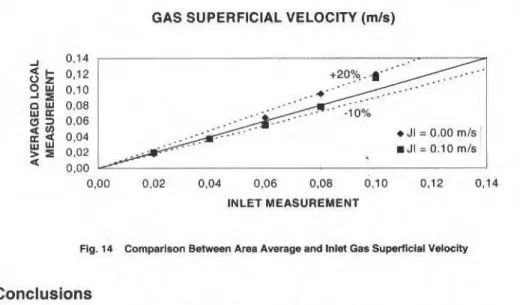
With a probe H'irh two sf.ns(lrs di.çpfLu:ed axially. the bubble interface velociry could be detemlined fmm the time
<lehJ.•· which gan1 rruuimum correlaúon between 1he sensor respnn.ses. These valtu•s of gas vl'locity in conjunction
wilh vohl fractions could be imegrared 10 give ave roge gas superficial velocities. V alues detemtined in tltis manner
were compared to value5 fmm rhe inler gas jlowrare measurements wul showed an average deviarion o.f /es.1· than 6% .for bubbly fluw.
Keywords: Two-Phnx<' Fim•·. lnslrumertllllion, Local Measurt'mew. Rl!.vistivity Probe, Double Probe
lntroduction
Two-phase tlows consisting of sirmiltaneous Oow of liqu id-vapor or liquid-gas are encountered quite frcquently in power generation systems. heat exchangers. chemical reactors, oil industry and othcr indus trial processes. ln these two-phase tlows, severa! flow regimes are encouotered where the gas phase may occur in various patterns, from small bubbles to large slugs oras a contin u ou.~ phase with or without liquid fi lms or droplets. The bubble size and their distributions io these regimes vary with the liquid and gas superficial velocities. flow geometry and local conditions. A detailed knowledge of the flow regi mes and local Jlow characteristics is very important in developing predictive tools. ln addition. theoretical modeling of two-phase tlow studies is often based on very specific local bydraulic conditions. An experimental verification of such analytical descriptious thus requires a very fine and detailed deterrn ination of the relevant local parameters.
ln the study of two-pbase t1ow thcre has been a strong need for instruments able to m ea~ure lhe
detailed distribution of various local parameters. such as the distribution of tl1e two phases. the bubble size dist.ribution and the bubble frequency.
One of the requirements of a suitable measw·ing method would be the absence of obstructions in the flow channel. Atleast three methnds meet this requirement: laser-Doppler anemometry. ul trasonic pulse transmission and particle image velocimetry. Howcver. these methods are only applicable where the dispersed phase is sufficiently di lute, i.e .. for low void fractions.
ln view of the intention to measure local variables in gas-liquid flows with void fraction possibly ranging from r.ero to unity it is inevitable to use a probe technique. ln a recent review work. Cartellier and Acbard (1991) have shown that the most powerful probe techniques are elect:rical resistivity probe. optical probe and hot film anemometry. Among these tecbniques. the advantage of electrical resistivity
L.F.M. Moura et ai.: Local Meaaurements ln Two·Phase Flows ... 459
probe is that both the sensor and the detecting electronic circuit are easy to be realized. ln this work., a double sensor resistivity probe was used for the measurement of the radial profiles of void fraction, bubble frequency, bubble interface velocily, interfacial area concentration and Sauter mean diameter.
Since the fundamental works of Serizawa et ai (1975) and Herringe and Davis (1976). continuous progress has been made with respect to the application of electrical resistivity probe technique Lo studying local two-phase tlow parameters. Progress has been done both on lhe sensor geometry and on tbe threshold procedure. The experimental work of Van der Welle (1985) was dedicated to lhe local measurement of the void fraction, bubble velocity and bubble size io air-water flows, usíng a double probe. Kataota et ai. (1986) introduced
a
local fonnulation of the interfacialarea
concentration and proposed a three double-sensor probe. Teyssedou and Tapacu (I 988) used a single probe for the. rueasurement of tbe void fraction profile in air-water flows. ln tbe work of Bamea and Shemer ( 1989)a
single probe was used for the measurement of the void fraction at the centerline of a vertical pipe in upward air-water tlow. Kocarnustafaogullari and Wang (1991) presented an extensive work on lhe local measurement of lhe void fraction, ioterfacial area conceotratioo, mean bubble diameter and bubble interface velocity in a horizontal air-water flow, using a double probe. Liu and Bankoff (1993) developed a miniature double probe for the local measurement of the void fraction. bubble velocity and buhble size in air-water bubbly flow. ln the work of Leung et ai. (I 995) a double probe was used to the study of tbe axial development of the iruert'acial area and void fraction profiles.
The Elect rical Resistivity Probe Technique
Measuring Principie
ln principie the electrical resistivity probe method consists of a instantaneous measurement of lhe local electrícal resistivity in the two-phase tlow by means of a sensor electrode. A typical resistivity probe is depicted in Fig. I.
uninsulated
I
lenglh
v
secood
---+ electrode
insu.lation
wire
Fig. 1 Typlcal Reslstlvlty Probe
Basical.ly the sensor works as an identifier of a phase surrounding the probe tip. Since lhe circuit is opened or closed depending on whether lhe sensor is in contact wilh gas or liquid, the probe behaves in principie likc a switch, yielding a two-stagc signal. Such a signal shows a nearly immediate response to water contact wilh the probe. but a delayed response to bubble contact, due to the required dewetting time of the probe tip. lndeed. the sensor does not penetrate the interface without defonning iL Moreover, tbe instantaneous resistiviry de.pends on the fraction of the sensitive tip area wetted by one phase. and therefore, long sensitive length induces smooth signal transitions. Minimization of thís delay. i.e .. approxímation of a square wave shape. is desirable for signaJ conditioning. However. to obtain a true square wave Lype signal, a proper i:hreshold voltage has to be used as a triggering critcrion. The value of threshold voltage can be obtained by processing the data for void fraction and by comparing it with other reference measuring method.
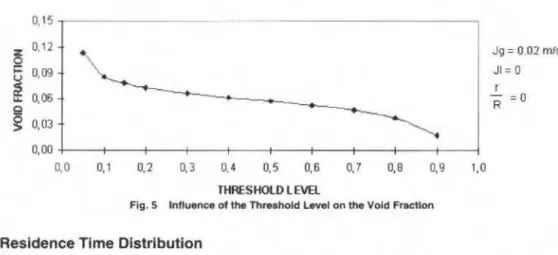
Signal Conditioning
460 J. of lhe Braz. Soe. Mechanical Sciences- Vot. 19. Oecernber 1997
succession of gas residence times. This approach has the inherent disadvantage that signals which do not reach the threshold levei will be undetected. Hence the threshold levei must be set as dose to the liquid signal levei as possible, in order to minimize the influence of the dewetting time and to take accounr of small bubbles.
No agree.ment exists in the literature. neither for the recommended threshold levei. nor for the resulting performance. Nevertheless. the threshold levei usually ranges from 10% to 50% of the static high levei signal.
The problem is further aU!,'mented in practice by sbifts in the liquíd signaJ leveJ. This problem can be avoided by comparing the samples with a self-adjusting threshold levei. First the data were divided in many data blocks (typically 16000 samples). Before
a
data block entered a phase discriminationroutine. the maximum M and the minimum N values of signal were determined in advance. The
threshold levei Tis given by:
T=(M-Nj · S+N (L)
where S ranges from zero to one.
The main advantage of this phase discrimination method is that every data block has a Jlexible threshold levei, even for the sarne value of S. This is of practicaJ importance if the líquid signaJ levei drifls.
Signal Processing
As the conditioned signal consists of a tra.in of square waves, the signal has to be processed such that lhe local parameters can be obtained.
The local void fraction is defined as the time average of the phase indicator function X hy:
T
a= lim
.!..J
X( x. 1 )d1'~'""' ""T
o
(2)
in which X as a funclion of positioo x and time 1 equaJs one for the gas phasc and zero for the liquid phase.
As lhe conditioned signal is given in discrete binary form. Eq. (2) can be written as:
(3)
in which N is lhe total number of samples and X( i) lhe binary sigoal
Tbe resideoce Lime for a bubble foUows from tl1e block lengtb of the square wave signal, i.e., from
the number of continuous samples n in the gas phase. and from the sampliog frequency.f:
(4)
LF.M. Moura et ai.: Local Measurements ln Two-Phase Aows ... 461
the bubble. lt is of course possible that a bubble is only pierced by one of the probes; lhis error source should not cause any problems provide this stochastic process is observed over an adequate length of time. A correlation technique will be required to determine the most probable time. delay between two
stochastic signals. Tbe cross-correlatioo fuoction of the two probe signals a and b is defioed by:
T
f'm,(x,T) = lim !...Ja(x.t)b(x+d,L+'C)dt
T -+ .. T
o
(5)
where d is the distance between the probes and 'C is lhe time delay. The maximum of the correlation function yields the most probable time delay r0 , from which the bubble interface velocity component in lhe axial dire<:tion is determined as:
d
V ; =
-To
(6)For two identical signals shifted relative to each other the correlation function yields a triangular sbaped function. ln case of nonidentical signals, i.e., when the width of the blocks differs. the lop of the correlatinn function is broadened, whlch may generate difficulties in determining -r-0 . ln practice,
however, the correlation functions show a single maximum. Jt can be shown that the error in
deterrnining r0 is inversely proportional to t:he number of samples within the time delay
r
0 , that is, if the sampling frequency is sufficiently large, the error in the measured velocity can be kept sufficiently low.The chord length I of a bubble follows from the block length of the square wave signal, i.e .. from the number of continuous samples n in tbe gas phase, and from lhe bubble interface velocity v; obtained from Eq. (6):
fi I'· 1=--'
f
wherefis lhe sampling frequency .
(7)
The transfom1ation of a cbord length into a bubble diameter remains problematic, as a certain chord length can correspond to a small chord in a large bubble or a large chord in a small bubble. Moreover,
the velocüy of Lhe bubbles may differ. This problem may be overcome if the foiJowing assumptíons are
ma de:
• the bubbles are spherical;
• the probe has equal probability of piercing any point on tbe projected frontal area of the bubbles; • ali bobbles travei in the sarne direction with the sarne average velocity.
lf lhe probability density function of the measured chord lengths is denoted by g(l) and that of the detected bubbles diameter by j( d). it is shown by Herringe and Davis ( 1976) that:
j ( d} =
~
( g( I )-/g' ( 1.1)(8)
462 J . ot lhe Bra.z. Soe. Meehantcal Sciences-llol. 19, December 1997 second one of lhe above assumptiom ralher doubtfuJ. and in some works lhe bubble d.iameter is
as~umed to be cqual to lhe measured chord length. so lhatftd)= g(l).
lt must be noted that the distribut.ion functions and mean diametcrs obtained are only representative of derecred bubhles. The spectrum of detected bubbles will in general not be representaúve of the spectrum of existing bubbles. as lhe probability for the probe to dete.ct a bubble is inversely pmport.ional to thc cross-secrional area of tbe bubble, i.e .. db'· lf we denote lhe probability density function of lhe detected buhbleb by fld) and lhat of all bubbles wilh cemer passing lhrougb a unit area of the cross section by j(d), it is shown by Herringe and Davis (I 976) lhat:
(9)
where
k
=
.:!...:2!...
1C Nb
in which nb is lhe number of detected bubbles ano Nb is tbe total number of bubbles passing tbrough a unit arca. The function j(d) will yield a much narrower bubble siu: range and mucb smal ler mean diameters than thosc obtained from lhe functionfld) duc to lhe d:ivision by db'·
The time-averaged interfacial
area
concentrntioo a; can be obtained by counting thc number of interfaces passing lhe probe per unit time N, and I<Ilowiog tbc interfacial velocity v1 and lhe anglc tf>between this vclocity and the normal vector of lhe interface (Kat.aota et ai., J 986):
- 2AI I
Uj{ X)- n 1
-1
-1
-v, t·vsif! ( lO)
ln practicc. 11 is difficul! to determine the angle ~. However. with lhe assumption lhatlhe interfaces are composed of spherical bubbles. thc probe passes every part of bubble wilh an equal probability and lhe iutcrfacial velocity has Lhe sarne direction of lhe probe tips. lhe interfacial area concentration can be deterrnined (Vetau. 198 I) by:
I a;( x)=4N1-I
I
\.';
(li)
The pro files of thc interfacial area concentraúon and lhe void fraction can be u .~ ed to determine the Sautcr mean bubble diameter variaúons along the cross section. The defmítion of lhe Sauter mean bubble diameter al>sumes sphcrical bubbles and is given by:
(12)
where nt i::. lhe number of bubblcs nf si.ce Dk and N1 is the total bubble si.te classes.
From the definitions nf vmô fract.ion and interfacial arca concentratíon for sphcrical bobbles. it can be shown thnt:
D sm(X ) = - --6 a( x)
LF.M . Moura et ai.: Local Measurements ln Two-Phase Flows 463
Experimental Results
Oescrlptlon of the Experimental Faclllty
A schematic diagram of the experimental facility is illustrated in Fig. 2. Tbe test section is made of a 80 mm 1D Plexiglas tube which is 1600 mm long. The local measurement station is located at
UD=l5.
T he air flow was supplied from the building central air system. The ai r Oowrate was controlled and
measure-d with a mass tlow controller BROOKS-585 1-E. The tap watcr flowrate was mea~ured with a
rotameter. Both air and water were injected into the mixing chamber placed at lhe bottom of lhe test section. The bubbl e generator consisted of a porous plate. At the top of the test section a constant levei system allowed the ai r to be exhausted and lhe water to be drained.
The. experimental conditions are summariz.ed in Table I. The gas tlowrate and superíicial velocity are always expressed at lhe calibration conditions (0°C and 101 KPa) .
LID= l5
•
••
•
•
to the drain
local probe
porous plate
air/water injection
Fig. 2 Schemetlc of the Experimentei Feclllty
Table 1 Experimental Flow Condltions
Úquid.flowrate (m%)
Superficialliquid
velocity (m/s)
Gas ftowrate (m%)
Superficial gas
velocity (m/s)
0.36 0.02
0.72 0.04
o
o
1.09 0.06
1.81 0.10
1.45
0.08
464 J. of the Braz. Soe. Mechanical Scle~ces- Vot. 19, Oecember 1997
The Electrical Resistivity Double Probe
The local measurement station conststs of a probe displacement mechanism. Lhe electrical resistivity doublc ~en~or probe and the driven vo lta ge-~e n sitive circuit. The doublc se nsor probe was inserted in the te.st secllon thruugh a probe support rubc (3.0 x 2.0 mm) fixed to the displacement mechanism. A Vemier. walh graduations to an accuracy of 0.05 mm, was used to traven.e lhe probe ia the radíal threction. A hlgh resolution mechanism was necessary to evaluate probe positions in tlow strean1 accurately and to ensure reproducible resuiLS.
The design of the electrical resistivity sensor is shown in Fig. 3. For each sensor, one electrode is the exposed tip of an otherwise isolated wirc and the return electrode is tbe supporting tube. The inner electrode is a 150 ).1111 diameter stainless steel wire, accurately cut under a microscope at the tip. The con ical tip of lhe sensor wos mode a~ shnrt a~ possible (30 JJID) to minimize lhe effect of bubble defom1ation. ll1e stainless steel wire was inserted into a 0.2 mm i.d. lhin plastic sleeve. This plastic tuhe containing the sensor was then inscrted into a
0.6
mm i.d. x1.0
mm o.d. stainless steel tube. Epoxy insulauon was applied to the emire sensor and allowed to run back whilst drying. to ex pose only a small tip area. The ex.posed length was about 250f-1rn .. Tbe axial distance between lhe tip of the two sensors was3.8
mm .stainless steel tube 1.0 x 0 .6 mm
insuJating plastic
tube 0 .5
x
0 .2 mmt::::\
l o
insulating epoxy
250 ~-tm
Fig .. 3 Deslgn of lhe Electrlcal Reslstivlty Double Proba
Each ~ensor was driven by a voltagc-sensitive circuit consisting of a 1.5 volt battery anda 2.2 MD
potenuometer connected in series with the prohe to the ground. Tbe potcntiometer wa ~ adjusted to give
an Oplimum output voltage for mea ~ure m e n ts. lf lhe sensor tip is in lhe liquid pbase, tbe circuit will be closed and the vultage output will be lowcr. When a gas bubble bits lhe sensor tip. lhe circuit continuity wiJ I bc brol..cn and the..output will read a high voltage. The voltage drop across the probe during closed circuit (liquid signal) appmximated 0.3 to 0.4 volts. Thi s low voltage effectively reduced electrochemical phenomena at the se nsor.
For each preset experin1cntal condition lhe probe signals were digiti1.ed by a data acquisition system
utilizing a personal computer and a Keithlcy-MetraByte DAS-1401 high-speed analogue-digital UO
expnnsion board.
A 1ypical resistivity duuble probe rcsponsc in two-phase bubbly flow (4 kHz sample rate) is shown in rig. 4. lt can be observed the time shirt between the signal of Lhe 1wo sensors as a bubble passes through the probe.