Eder Paduan Alves* Institute of Aeronautics and Space São José dos Campos - Brazil ederep@yahoo.com.br
Francisco Piorino Neto Institute of Aeronautics and Space
São José dos Campos - Brazil piorinofpn@iae.cta.br
Chen Ying An National Institute for Space Research
São José dos Campos - Brazil chen@las.inpe.br
*author for correspondence
Welding of AA1050 aluminum with
AISI 304 stainless steel by rotary
friction welding process
Abstract: The purpose of this work was to assess the development of solid state joints of dissimilar material AA1050 aluminum and AISI 304 stainless steel, which can be used in pipes of tanks of liquid propellants and other components of the Satellite Launch Vehicle. The joints were obtained by rotary friction welding process (RFW), which combines the heat generated from friction between two surfaces and plastic deformation. Tests were conducted with different welding process parameters. The results were analyzed by means of tensile tests, Vickers microhardness, metallographic tests and SEM-EDX. The strength of the joints varied with increasing friction time and the use of different pressure values. Joints were obtained with superior mechanical properties of the AA1050 aluminum, with fracture occurring in the aluminum away from the bonding interface. The analysis by EDX at the interface of the junction showed that interdiffusion occurs between the main chemical components of the materials involved. The RFW proves to be a great method for obtaining joints between dissimilar materials, which is not possible by fusion welding processes.
Keywords: Friction welding, Aluminum, Stainless steel, Dissimilar materials.
INTRODUCTION
During recent years, the use of joints between dissimilar materials has considerably increased. Conventional structures made of steel have been replaced by lighter materials, capable of providing high mechanical strength, lower volume of material and good corrosion resistance.
In the developing of new technologies for the aerospace industry, these junctions are of great importance, because they allow the systems, subsystems and components manufactured in stainless steel and aluminum to be structurally united. Even the fusion welding processes by presenting a heat affected zone (HAZ) well reduced (as laser and electron beam welding processes) generate junctions with inferior properties of the base metal.
The difficulties in the welding of aluminum alloy with stainless steel by fusion welding processes have been a great challenge for engineering, because they result from hard and brittle intermetallic phases that are formed between aluminum and steel at elevated temperatures (Fe3Al, FeAl, FeAl2, Fe2Al5, FeAl3). The Fe-Al phases diagram shows the well defined intermetallic phases (Banker and Nobili, 2002).
In order to obtain junctions between the AA1050 aluminum (commercially pure aluminum, 99.5% Al) and AISI 304 stainless steel for structural applications that can be used in the aerospace sector, several studies and analysis of welding processes were carried out. Among them, rotary friction welding process(RFW) showed the best result.
In this study, these materials have been joined by RFW and the results were analyzed and presented. Tensile tests were performed to define welding parameters and analyze the resistance of the weld. After obtaining the best results (the fracture occurred away from the bonding interface) in the AA1050 aluminum (lower resistance), the process was optimized and analyzed in the bonding interface by optical microscopy, electron microscopy of EDX and Vickers microhardness test.
ROTARY FRICTION WELDING PROCESS
Friction welding process is classified by the American Welding Society (AWS) as a solid state joining process in which bonding is produced at temperatures lower than the melting point of the base materials (M
aldonado-Zepeda, 2001).
All heating responsible by the union is mechanically generated by friction between the parts to be welded. This heating occurs due one part that is fixed, be pressed on the other that is in high rotation (Wainer, Brandi and Homem
Received: 26/06/10 Accepted: 06/10/10
de Mello, 2002). The friction between the surfaces makes possible a rapid temperature rise in the bonding interface, causing the mass to deform plastically and flows depending on the application of pressure and centrifugal force, creating a flash. With this flash, impurities and oxides are removed from the surface, promoting the creation of a surface with excellent physical and chemical adhesion. The increase of temperature in the bonding interface and the application of pressure on that surface originate the diffusion between the two materials, and hence their union.
The main parameters used to perform the set up are: Pressure P1 and time t1 – heating phase; Pressure P2 and time t2– forging phase; and rotation per minute (RPM). Figure 1 shows the phases of the process.
Figure 2 shows the basic layout of RFW equipment. Usually the structure is fairly rigid to provide stability to the equipment working at high speeds and is driven by high pressure forging. Modern equipment is automatic and allows all the parameters be adjusted, controlled and monitored directly on the control panel.
Figure 1: Phases of conventional friction welding process. (A)
Period of approximation; (B) P1, t1 application; (C)
end of P1, t1 application, and braking of the machine
(RPM = 0); (D) P2, t2 application and finish welding.
Figure 2: Equipment of rotary friction welding.
Table 2: Mechanical properties of materials used in present study
Material Mechanical properties
Strenght σ (MPa) Elongation ε (%) Modulus of elasticity E (GPa) Yield Maximum Maximum Fracture
AA1050 aluminum 44.70 78.48 21 43 59.12
AISI 304 stainless steel 354.69 643.79 48 63 177.10
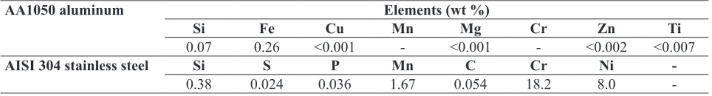
Table 1: Nominal chemical compositions of materials
AA1050 aluminum Elements (wt %)
Si Fe Cu Mn Mg Cr Zn Ti
0.07 0.26 <0.001 - <0.001 - <0.002 <0.007
AISI 304 stainless steel Si S P Mn C Cr Ni
-0.38 0.024 0.036 1.67 0.054 18.2 8.0
-EXPERIMENTAL PROCEDURE Materials and surfaces preparation
The materials used in this study were AA1050 aluminum (commercially pure aluminum, 99.5% Al) and AISI 304 austenitic stainless steel. Both materials were machined with a diameter of 14.8 mm and lengths of 100 and 110 mm, respectively. After machining, they were subjected to a cleaning with acetone to remove organic contaminants such as oils, greases etc. Tables 1 and 2 present chemical compositions and mechanical properties of materials.
Friction welding equipment
Tensile tests
After welding was performed, tensile tests were carried out to evaluate the mechanical properties of joints, besides parameter settings, optimization and qualification of welding procedures and processes. The welded specimens were machined according to ASTM E 8M (2004), and subjected to tensile tests on a machine brand ZWICK 1474 with a load cell of 100 kN at room temperature of 25°C, and a test speed of 3 mm/minute.
Vickers microhardness tests
A sample with the same parameters of the junction which showed 100% of efficiency was analyzed by Vickers microhardness using a digital microhardness tester (Future-Tech Corporation, Japan) with a 300 gF load (stainless steel) and 100 gF (aluminum) for 10 seconds. Microhardness was conducted at the interface of the weld and in the regions near both the aluminum and the AISI 304 stainless steel sides.
Metallographic analysis
The joints were cut in the transverse weld, embedded in an array of bakelite, polished and examined in the region of the interface on the aluminum and AISI 304 stainless steel sides, according to ASTM E3 (2007). Aluminum was attacked with Keller reagent and stainless steel with electrolytic acid oxalic 10% and examined under a microscope (Leica DMRXP, Spectronic Analytical Instruments, United Kingdom).
Analysis of the bonding interface
In order to verify the main bonding mechanism by friction − the diffusion − analyses were carried out by scanning electron microscopy (SEM) and energy dispersive X-ray spectroscopy (EDX) at the bonding interface on the central
region and ends of the sample. It was used an electron microscope (JSM 5310, Jeol Ltd., Japan), allocated in the Associate Laboratory of Sensors and Materials of the National Institute of Space Research (INPE, acronym in Portuguese).
RESULTS Macrostructure
In macrostructure level, it was observed the formation of flashes with circular symmetry, different formats, and also significant reductions in length of the cylindrical pin AA1050 aluminum in accordance with the adopted parameters. The AISI 304 stainless steel side was not deformed because this material has higher strength than the aluminum alloy, and it thus provide more resistance to deformation. Hence, the formation of flashes was restricted to AA1050 aluminum only.
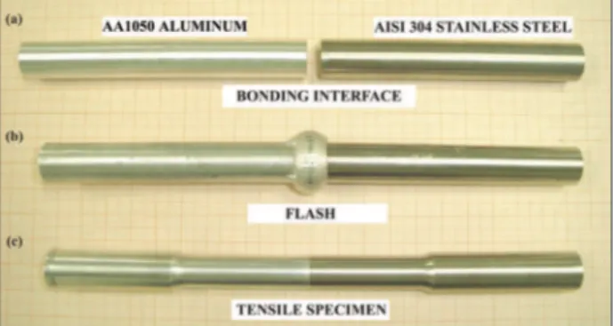
Figure 4 shows the interfaces that were bonded (A), the flash generated by RFW (B), and the specimen used for tensile test after machining (C).
Figure 3: Schematic view of the positioning of the materials before welding.
Figure 4: Interfaces of pins that were joined (A); flash
generated by the process (B); specimen for tensile test (C); samples on graph paper.
Mechanical strength of the joint welded by friction
The results of tensile tests for different welding parameters used (t1, t2 and P2) are shown in Table 3. The junction with the best mechanical strength (σt max.) refers to the specimen number 8, with higher mechanical strength to the material with lower mechanical strength − aluminum AA1050.
Figure 5: Specimen number 5: (A) − rupture on the bonding interface; specimen number 8: (B) − rupture away
from the bonding interface.
Figure 6: Specimens number 1, 2 and 3 − AA1050 aluminum/
AISI 304 stainless steel after completion of tensile tests.
The welding pressure P2 = 1.4 MPa, applied at time t2 = 2 seconds on heated interface, completed the welding with desired strength. The results also showed that when there is an increase in the P2 pressure values, the joint strength also increases until it reaches its limit and then decreases again. Everything indicates that this occurs due to increased plastic deformation resulting from the application of excessive pressure P2 when RPM = 0.
The relative speed (RPM), the pressure P1 and the time t1 are essential for the occurrence of temperature elevation at the bonding interface and diffusion of the materials involved, while P2 and t2 are responsible for the completion of welding. When there is no interaction between these various parameters involved in the process, the joint loses its quality, because unbonded regions or the formation of undesirable intermetallic layers may occur at the bonding interface, resulting in lower joint strenght than that of the base aluminum alloy.
Figure 5 shows the specimens number 5 and 8 after they were tested and removed from the tensile test machine.
Vickers microhardness tests
Vickers microhardness tests were performed from bonding interface to AA1050 aluminum, and also from bonding interface to stainless steel AISI 304, central region. In the AA1050 aluminum, a slight increase of Vickers microhardness has occurred as the interface was approached (points 1, 2, 3 and 4); from point 5 to 20, the average value of measurements (30.9 HV) represents the typical value of AA1050 aluminum microhardness (30.0 HV) (AALCO, n/d). On the side of AISI 304 stainless steel, the results also showed an increase of microhardness values as the points were close to the bonding interface. This variation in microhardness values occurred from point 1 (highest) to point 12. From the point 13 to 20, the average value of measurements (198.8 HV) refers to the typical value of microhardness of AISI 304 stainless steel used in this work.
On the side of AA1050 aluminum, the increase of Vickers microhardness values near the bonding interface occurs due to the large plastic deformation underwent by this material and temperature raises in this region. By the side of AISI 304 stainless steel, everything indicates that the increase of microhardness values near the bonding interface is derived from the increase of temperature and displacement of the heat flow in these regions, since the material does not undergo considerable plastic deformation during welding, as occurs with AA1050 aluminum.
Figure 7 shows the variation of Vickers microhardness values through the graphs microhardness (HV) x distance bonding interface, for AA1050 aluminum (a) and AISI 304 stainless steel (b). The dotted lines express the microhardness values (HV) of the materials used in this work.
Figure 8 shows that, on the alloy AA1050, the region with the variation of Vickers microhardness as a function of plastic strain (1, 2 and 3) reaches a maximum distance of the bonding interface of about 0.7 mm.
Metallographic analysis of the bonding interface
Figure 9 shows a photomicrograph of the junction between AA1050 aluminum and AISI 304 stainless steel, taken in
Table 3: Tensile tests
Nº P1 (MPa/psi)
t1 (s)
P2 (MPa/psi)
t2 (s)
σt máx
(MPa) 1 2.1 7 2.1 2 72.0
2 2.1 17 1.4 1 64.12
3 2.1 17 2.1 1 69.63
4 2.1 27 1.4 1 62.94
5 2.1 32 0.7 1 47.45
6 2.1 32 0.7 2 53.37
7 2.1 32 1.4 1 70.63
8 2.1 32 1.4 2 80.08
9 2.1 32 2.1 1 74.23
10 2.1 32 2.8 1 76.54
Figure 7: HV microhardness x distance bonding interface. (A) AA1050 aluminum; (B) AISI 304 stainless steel.
Figure 8: Photomicrograph of the bonding interface between the AA1050 aluminum and AISI 304 stainless steel,
showing the measuring points and the approximate
distance in scale of the regions that presented a variation of the Vickers microhardness values.
Figure 9: Photomicrograph of the interface bonding between the AA1050 aluminum and AISI 304 stainless steel with an increase of 100 X.
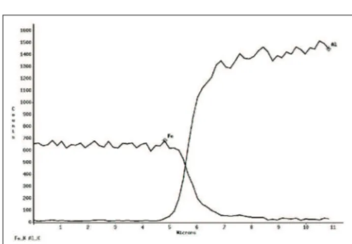
steel, like Al and Fe. Figure 10 shows the interdiffusion between Fe and Al, characterizing the diffusion as the main bonding mechanism in the rotary friction welding process, according to Fukumoto et al. (1997; 1999), Fuji et al. (1997), Kimura et al. (2003), and Ylbas et al.(1995).
The Al diffused less in Fe than Fe in Al, and a reason for this is the smallest diameter of Fe atom in relation to Al. Another reason for the different distances from the diffusion zone is the different concentrations of Fe and Al contained in each material.
Junctions obtained through the rotary friction welding process
The great finish in the welded regions and the absence of surface defects (Fig. 11), so common to fusion welded joints, show the efficiency of this process in welding the central region of the sample with an increase of 100 X.
The interface region is characterized by a straight line with some imperfections under the friction welding process. Both in the aluminum and stainless steel sides, microstructural changes are not observed near the interface region, as it occurs in fusion welding processes. All plastic deformation resulting from the parameters used in the process occurred in the AA1050 aluminum, due to the fact that this material has lower strength and lower hot forging temperature.
Analysis of the bonding interface by energy dispersive X-ray spectroscopy
materials that are highly dissimilar, as AA1050 aluminum and AISI 304 stainless steel. The efficiency of this welding process (analyzed by tensile tests), its repeatability and high productivity open new possibilities of alternative processes for obtaining joints between dissimilar materials with applications in aerospace field.
CONCLUSIONS
The friction welding process was very efficient in the welding of dissimilar materials such as AA1050 aluminum and AISI 304 stainless steel. It is showed by the results of tension mechanical tests that presented mechanical properties which are not possible to achieve by means of fusion welding processes.
Among the parameters used for testing the welding, the one that showed the best results in tensile tests − with superior values of mechanical strength of the AA1050 aluminum − was number 8 (Table 3), in which P1 = 2.1 MPa; t1 = 32 seconds, P2 = 1.4 MPa; t2 = 2 seconds.
Vickers microhardness values measured in the side of AA1050 aluminum and in the side of AISI 304 stainless steel, near the bonding interface, central region, were higher than in the metal bases. As the measurement points move away from the interface, they decrease until they reach the reference values of microhardness for each material.
The results of this study have fundamental importance for the understanding and comprehension of the main characteristics of friction welding process, the bonding mechanisms between dissimilar materials, and the feasibility of applying this process in the production of structural joints that will be used in aeronautic and aerospace industry.
REFERENCES
AALCO, n/d, “Aluminium alloys − Aluminium 1050 proprierties, fabrication and applications, supplier data by Aalco. Typical mechanical properties for aluminum alloy 1050” Available at: www.azom.com/details. asp?ArticleID=2798#_Alloy_Designations
Banker, J., Nobili, A., 2002, “Aluminum-Steel Electric Transition Joints, Effects of Temperature and Time upon Mechanical Properties. Draft of paper for presentation at 2002 TMS 131st Annual Meeting”, Seatle, WA, USA.
Fukumoto, S. et al., 1997, “Evaluation of friction weld interface of aluminum to austenitic stainless steel joint”, Materials Science and Technology, Vol. 13, Nº. 8, pp. 679-686.
Fukumoto, S. et al., 1999, “Friction welding process of 5052 aluminum alloy to 304 stainless steel”. Materials Science and Technology, Vol. 15, Nº. 9, pp.1080.
Fuji, A. et al., 1997, “Mechanical properties of titanium - 5083 aluminum alloy friction joints”, Materials Science and Technology, Vol. 13, Nº. 8, pp. 673-678.
Kimura, M. et al., 2003, “Observation of joining phenomena in friction stage and improving friction welding method”, JSME International Journal, Series A, Vol. 46, Nº. 3, pp. 384-390.
Maldonado-Zepeda, C., 2001, “The effect of interlayers on dissimilar friction weld properties”, PhD thesis, University of Toronto, Canada.
Wainer, E., Brandi, S.D. and Homem de Mello, F.D., 2002, “Soldagem: processos e metalurgia”, 3. ed. São Paulo: Edgard Blücher.
Ylbas, B.S. et al., 1995, “Friction welding of St-Al and Al-Cu materials”, Journal of Materials Processing Technology, Vol. 49, Nº. 3-4, pp. 431-443. doi: 10.1016/0924-0136(94)01349-6
Figure 11: Joints produced by the rotary friction welding process (RFW) (dark part: AISI 304 stainless steel; clear part: AA1050 aluminum).