Abstract— This article presents a study case and practical application of a system controller update for a power control center. This system was designed and developed by Simulation Department of the Instituto de Investigaciones Eléctricas and it is one more of the technological developments carried out here. The technology of the system controller has operated for several years and worked properly providing, in a reliable way and with high availability, information to the operators at a control center, the state of the feeder switches and the substations of the Electric Power Network of the main metropolitan zone of the country, therefore guaranteeing the supervision of safe and reliable operations. Final results during functional tests are also analyzed and tendencies of this development within operators’ scope are also presented.
Index Terms— Control center, control room, communication protocol, controller, power plant.
I. INTRODUCTION
HE Instituto de Investigaciones Eléctricas (IIE*, Mexican Electric Research Institute, http://vmwl1.iie.org.mx/sitioIIE/site/indice.php) was founded on 1975 and started its operations. It has been the right hand as R&D institution of the Mexican electrical utility, offering technical innovations. The Simulation Department (SD), one of the technical areas of the IIE, has developed, installed, and integrated computer software and hardware systems in order to put on service and support new and advanced technical platforms of simulators for training personnel that operates power plants in control rooms. It also provided technical equipment for operators that supervise and control different electric power networks in a control center of the electrical utility companies. In this paper, a system controller conversion of an operation control area is presented and its different parts are described within
Manuscript received March 21, 2011; revised March 01, 2011. These works were supported in by the LyFC, under contract code SS-185/93 and CM-001/2004.
E. Zabre is with the IIE, Reforma 113, Col. Palmira, Cuernavaca, Morelos, 62490 México, (phone: 777-362-38-11; fax: 777-362-38-17; email: [email protected]).
R. Román is with the IIE, Reforma 113, Col. Palmira, Cuernavaca, Morelos, 62490 México, (phone: 777-362-38-11; fax: 777-362-38-17; email: [email protected]).
* Some acronyms are after the name or phrase spelling in Spanish.
the supervisory and control purposes. The developed system controller technology involves several areas and to reach these goals, different specialists were required. Engineers of software, control, communications network, maintenance and tests and faults have shared the same commitment.
II.BACKGROUND
In 1994-95, the IIE’s Electronic Department put on operation a new platform SAC IBUS-III of control and data acquisition system, known as controller system for dynamic mimic panel (CSDMP®), used to act as a monitoring interface of the feeder switches and the substations (SS) of
the electric power network (EPN) of Mexico City’s
metropolitan zone, between a supervisory master station (MS) and a dynamic mimic panel (DMP) installed in a control center (CC). Preliminary tests were carried out at
Siemens™ (provider of the Empros™ Master Station) in
Minneapolis, USA; where engineers form the control center were trained to use, operate and put the CSDMP on service. The CSDMP worked properly and continuously during the next nine years though at the beginning of 2003, an electric fault in the CC appeared and the CSDMP began presenting instability during the process of starting operation. The CSDMP was re-established and put back on service to guarantee its availability and continued full functionality
At the present, the CC, Fig. 1, is operated by Comisión Federal de Electricidad (CFE, The Mexican utility company) [3] which is the manager of offering the electrical service in the whole country.
III. PROBLEM
Foreseeing the term of useful life of the CSDMP and going towards the expiration of technology that was used for the development of the CSDMP, the IIE proposed its substitution in the briefest term.
The challenge was to obtain the same requirements as well as the same hardware and software functionality of the original system.
In 2004-05 the SD developed a project with the purpose of substituting the SAC IBUS-III [1] old platform for a modern, compact and robust one, avoiding the long
interruptions of service to the CC’s operators were
supervising, achieving a high availability of the CSDMP.
A System Controller Update and its Tendency of
Information Deployment at a Control Center: a
Study Case and Practical Application
Eric Zabre, Rafael Román
Fig. 1 Center of Control and Operation of the metropolitan zone at Mexico City IV. PROBLEM
As shown in Fig. 1, the DMP measures 46x23 feet and it has been constructed with hundreds of 1x1 inch mosaics on which a set of lamps are dynamically distributed around it. All together represent the behavior of the EPN.
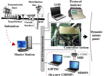
The CSDMP was settled on a serial network connected between a MS and a DMP as shown in Fig. 2.
Fig 2 CSDMP configuration in an RS-232 serial network The MS receives/sends information to/from remote terminal units (RTU). The information consists of the logical
state of the feeders’ switches and the SS of the EPN and
some analogical data as time schedule, current, voltage, and phases of different points around the EPN in the metropolitan zone. The MS, processes all concerning data,
putting it into a data base, updates a set of one-line diagrams, fills the proper protocol formats, and sends the message to the controller by means of an RS-232 serial communication channel. The controller receives the message, processes all data and through its digital outputs set values (on, off and blinking) to a lamps on a DMP. The states and the colors (red, green and yellow) of the lamps, represent different states (connected, disconnected, fault, and right operation) that are supervised and interpreted by the operators at the CCO to take a particular action when necessary. In addition to the visualization in the DMP, the operators can observe, in a redundant way, the behavior of the EPN in monitors at their Station Operator.
Additionally, there is a system diagnostic tool, for the old CSDMP, the local operation station (LOS), and for the new CSDMP, a graphic interface for protocol test in serial communication (GIPTSC®) was used, both capable to emulate MS commands by operator request and send it to the controller.
The following sections describe the transition process occurred from the old CSDMP platform to the new one.
V.CSDMPPLATFORMVERSIONSACIBUS-III
A. Hardware
SAC IBUS-III was a Control and Data Acquisition System generation of a family of I/O analog and digital electronic boards [1]-[2], communication interface, synchronization module, and microprocessor, among others, plugged to a common electric bus contained on a card cage
which was designed and developed by IIE’s Electronic
Department with the purpose of offering computer electronic Distribution
line
Transformer Transmission lines
Circuit break er
RTU Substation
RS
-2
3
2
S
eri
a
l
n
et
w
o
r
k
Master Station
Protocol Analyzer LOS
GIPTSC
MDSSN MID
COM1 COM2
(In a new CSDMP) Controller system
equipment for monitoring and handling devices of the real world.
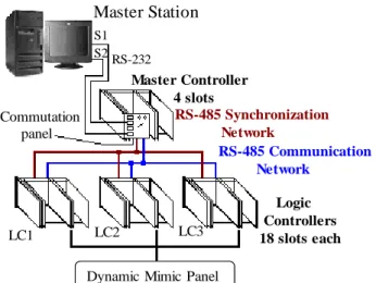
The CSDMP formed by SAC IBUS-III platform, shown in Fig, 3, consisted of one master controller (MC) which acts as the front end to the MS and three more slave controllers, known as logic controllers (LC) that receive data, transfer the final values to a DMP, and answer with a fault code to its MC. The LC are always communicating and synchronizing a real time clock (RTC) with its MC through internal RS-485 networks.
Master Station
S1S2RS-232
Master Controller 4 slots Commutation
panel
Logic Controllers 18 slots each
Dynamic Mimic Panel
LC1 LC2 LC3
RS-485 Synchronization Network
RS-485 Communication Network
Fig. 3 CSDMP SAC IBUS-III physical configuration Both the MC and the LC had in common some important characteristics as: IBUS-III backplane for electrical interconnection of digital outputs boards, +5V DC power supply, SAC-1887 CPU, synchronization module, RS-485 communication and communication module for LOS.
Fig. 4 Logic Controller SAC IBUS-III installed on the rear of Dynamic Mimic Panel
Additionally, in the MC there was a commutation panel with RS-232 channels for communication with two Servers of the MS, and in every LC there were 13 SAC-617/64 digital output boards with 64 channels each. A view of one LC is shown in Fig. 4
This CSDMP has been designed to drive 2,304 single digital outputs plus 12 Binary Code Decimal modules.
B. Software
Concerning software, it has implemented over a Concurrent Processes Operating System (CPOS). All
communications programs have been written on Intel™ assembler for the 8088 uP and 8039 microcontroller, and the
concurrent processes have been written on PLM86™
programming language. All programs together work as the supervisory application at CCO. Each program has different purpose: to initialize all necessary hardware, to read/write messages on serial channels from LC, to write data to buffer status, to decode protocol CIS (Computer Inquiry Systems) [6] messages from ME, including update of digital output signals (DO) and BCD modules, as well as verification the controller status and to generate error code.
VI. NEWSCTMPLATFORMVERSIONVMIC
A. Hardware
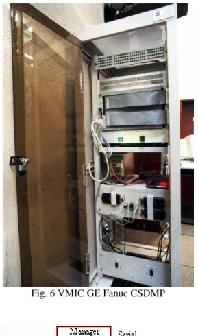
The new CSDMP, as shown in Fig. 5 and 6, is an embedded and generic system of I/O VMIC™ [7] electronic boards manufactured by GE™ Fanuc as follows.
VMIVME-0404 VMEbus backplane 21 slot computer chassis
+/- 12V DC Power supply
VMIVME-7805 Single Board Computer Intel Pentium 4 uP based on the VMEbus standard
VMIVME-7459 VMEbus CD-RW 20 GB Hard Disk 18 VMIVME-2128 128 bit high voltage DO board 18 VMIACC-BT04 Dual 96-pin transition panel RS-232 network and RS-485 network converters
Master Station S1
S2
RS-232
Tx/Rx/GND RS-232
External monitor, mouse & keyboard
Slots
01 ... 21
C
P
U
HD
R
/W
BCD Dig
it
al
O
u
tp
u
t
B
o
ar
d
s
128 Digital Output per boards
TDA(-) RDA(-) RS-485
To the old controller (Not used anymore) RS-232 485
Converters
RDB(+) TDB(+) RS-232
Dynamic Mimic Panel
Fig. 5 CSDMP VMIC GE Fanuc physical configuration
B. Software
The software of the VMIC CSDMP consists of a group of programs written on C++ using the following packages:
VMISFT/SW-7431 Windows 2000 operating system VMISFT-9420 VMEbus IOWorks software
Visual Studio.net™ 2003
controller status and to generate error code.
Fig. 6 VMIC GE Fanuc CSDMP
Fig. 7 Interconnection of the new programs and threads TABLE I
HW/SW of different CSDMP versions Parameter SCTM SAC
IBUS-III
SCTM VMIC GE Fanuc Hardware
Controllers 4 1
Digital output 2,304 2,304
Network RS-232
RS-485
RS-232 Ethernet
uP 8088 Intel™ Pentium 4
Software
Operating system SOPCO owner Windows 2000 Programming Assembler
PLM86™ C++ on Visual Studio.Net
The new CSDMP consists of a unique controller working exactly as before; however, with renovated hardware and
software which main differences are summarized in Table I. VII.AUXILIARYTOOLSFORTHECSDMP For the operative and functional tests of the new CSDMP, it was specified a tool of diagnosis supporting the development, testing and putting in operation of it.
This new interface, named GIPTSC [4], was intended to test any communication serial protocols and is based on the previous development: the LOS. Originally the protocol CIS but now it has been improved aspects of its functionality and would provide the user with additional abilities of diagnosis of the system but using the GIPTSC. An operator is capable to arm a CIS message, to send and receive commands emulating the Main Station across the communication channel series. See Table II.
TABLE II CIS protocol commands
Command Description
Tests Manual/Automatic point (lamp) Even/odd (red/green) bits Even/odd bytes BDC segment display All points and BCD displays Status system reestablishment Update on line Point’s state (up to 20 points) BCD display (RTC, Voltage, Current, and Frequency) Group points (up to 20 groups) Group point assignment (up to 80 points)
Diagnostic Point state/system status
*Diagnostic Points’ states recover *Message simulation
fault
Incomplete
Without terminator Additional data Wrong header Point out of range Fault reestablishment
The two commands, diagnostic and simulation fault, are exclusive of the GIPTSC for testing and fault simulation serial network purposes.
Additional to the functional tests, another diagnostic tool: a monitor for data supervision in serial network, known as MDSSN [5] was required to validate the messages that circulate around a serial communication network connected between a MS and the peripheral CSDMP with a physical adapter (MID) to serial communication ports, processing and updating of data, displaying the data obtained in a graphical way focused to users who process a particular data of this application. MDSSN is capable to substitute a commercial protocol analyzer.
Both the GIPTSC and MDSSN were developed using the software platform Visual Studio.net® and written on C++ programming language.
VIII.CDSMPCONVERSION
The migration to the new platform was realized with the previous platform still working, see Fig. 8.
peer, and though the messages were directed to both CSDMP. To avoid conflicts in the communication network, only the new CSDMP was enabled to answer to these messages and the digital output signals were migrated one by one.
The LOS and a Protocol Analyzer were used as auxiliary tools to put on line the new CSDMP.
...
... ... ...
LOS
...
Master Station
RS-232 485 Converters RS-232
RS-485
LOS
RS-232
New CSDMP
LOS Dynamic Mimic Panel
Old CSDMP MC SAC
LC1
MIGRATION
MIGRATION
LC2 LC3
Protocol Analyzer BT04
New DO Signal
Old DO Signal
Fig. 8 Coexistence of both CSDMP during migration of one by one digital output signals
This extremely important and delicate activity was carried out by the coexistence in line of both platforms due to the need, partially by the operators of the system, of being provided with the visualization in real-time of the information originated from diverse SS and switches associated in field, in the mimic panel. See Fig. 9.
Fig. 9 IIE’s Technicians connecting signals from the old
CSDMP to the new CSDMP IX. CONCLUSIONS
The former CSDMP validation was carried out at Minneapolis and the control center facilities by specialized personnel under rigorous acceptance controller testing procedures, and with a lot of experience in the use of SCADA applications, to ensure that this controller would fulfill the performance specified by the end user in order to have one more useful tool to supervise the correct operation of the Electric Power Network.
The new platform developed by the IIE provides a lot of
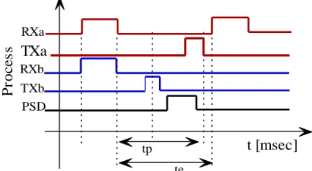
certitude and robustness to the new CSDMP behavior and this one reproduces correctly the same behavior that the previous CSDMP. See Fig. 10.
Where tp < te, considering that te = 25 msec, MS waiting time
tp = 20 msec, processing received message time and responds to MS
Last behavior (red):
RXa = identification and message processing TXa = answer to the previous received message
Actual behavior (blue):
RXb = identification and message processing TXb = answer to the previous received message
PSD = updating digital outputs before receiving next command from the MS
t [msec]
tp RXb
TXb PSD RXa
P
ro
c
e
s
s TXa
te
Fig. 10 RX/TX validation time of the CSDMP In a similar way, using GIPTSC and MDSSN auxiliary tools, during real time operation, an exploration of 12,000 message series was observed by 11 hours lapse, and the obtained statistics results demonstrated that the fault index was reduced to zero. See Table III.
TABLEIII Statistics messages
Message Statistic
Sent by Master Station to the CSDMP
Update point status 11,194
Turn off points 60
Subtotal updated points 12,000
Turn on all points +BCD 4
Turn on BCD 6
State reestablishment 2
Subtotal manual test 12
Point status 44
System status 328
Subtotal status request 372
BCD block update 45
Group update 8784
Group assignment 578
Errors on CSDMP messages sent to Master Station
Point status response 0 System status response 0
With the development and the commissioning of this new CSDMP, the IIE has demonstrated the capacity to penetrate into new technologies and once again it has supported our national utility companies, as enterprises hard linked to the electrical sector.
In the opinion of the final user, the evolution of the CSDMP has been satisfactory, since it classifies to this development in very good position inside the state-of-the-art technology.
Finally it is necessary to mention that this technological development have been worked since 2005 uninterruptedly neither reported faults.
X.FUTUREWORKSASTENDENCYOF INFORMATIONDEPLOYMENT
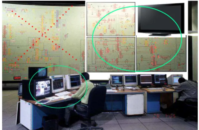
Because the control center is the fundamental part of the supervision and control of the EPN, there is a proposed project that consists in modernizing the projection technology for a more modern one [10], [11], [12] that offers at least the same service to the system operators. This means, to substitute steeply the visualized mosaic mimic panel by representative diagram images on Plasma Display (PDP) or Liquid Crystal Display (LCD) panels [8]. See Fig. 11.
Fig. 11 Modern projection of the representative mimic panel diagrams on PDP or LCD panels
ACKNOWLEDGMENT
The authors heart fully thank researchers and technicians of the IIE, especially from the Electronic Department and Simulation Department, and former Mexican electrical utility for their invaluable cooperation and support that have made this work possible.
REFERENCES
[1] IIE, Final documentation and technical reports of projects related to the development of the IIE electronic equipments.
[2] M.A. Martínez, Z. Flores, M.A: Delgadillo y R. Gutiérrez, Sistema
automático de pruebas para equipos de control en centrales de ciclo combinado, Boletín IIE, noviembre-diciembre 2001.
[3] CFE Comisión Federal de Electricidad http://www.cfe.gob.mx/en/ [4] Zabre E., Guzmán K., CIINDET 05, 3er Congreso Internacional sobre
Innovación y Desarrollo Tecnológico IEEE Sección Morelos,
Herramienta de diagnóstico para prueba de protocolos de
comunicación serie, www.ciindet.com.mx, Cuernavaca, México
28-30 Sep 2005.
[5] Zabre E., Ávalos J. H., Román R., CIINDET 2009, VII Congreso Internacional sobre innovación y Desarrollo Tecnológico IEEE Sección Morelos, Monitor para supervisión de datos en red serial, www.ciindet.org, Cuernavaca, México 7-9 Oct 2009.
[6] CIS DMux Control Unit User’s Manual, Operation Procedures Run/Lock Operation-Serial Interface, Siemens, 3-9.3-15.
[7] VMIC a GE Embedded Systems, Products VMEbus Access; I/O Connectivity IOWorks Board Drivers; Generic Device Driver; and Manuals, http://www.geindustrial.com/cwc/gefanuc/embedded/ [8] DLP, A Texas Instruments Technology, see beyond the screen”,
http://www.dlp.com, 2004
[9] BMI, Business Media Incorporated, Training Room, http://www.bmi-lcd.com/feat_3.html
[10] F. F. Wu, K. Moslehi, A. Bose, Power System Control Centres: Past,
Present and Future, Proceedings of the IEEE, pp. 1890-1908, Vol.
93, No. 11, November 2005.
[11] R. M. Robbins, State-of-the-art Control Rooms, Control Engineering Resource Center, http://mobile.controleng.com/article/268069-State_of_the_art_Control_Rooms.php, February 2009.
[12]B.VAIL,CONTROL ROOM DESIGN IN THE 21STC
ENTURY,
HTTP://WWW.ISA.ORG/INTECHTEMPLATE.CFM?SECTION=ARTICLE_IN
DEX1&TEMPLATE=/CONTENTMANAGEMENT/CONTENTDISPLAY.CFM