Advances in Mechanical Engineering 1–8
ÓThe Author(s) 2015 DOI: 10.1177/1687814015575976 aime.sagepub.com
A highly efficient Francis turbine
designed for energy recovery in cooling
towers
Daqing Zhou
1, Huixiang Chen
2and Chunxia Yang
2Abstract
In China, cooling water entering cooling towers still retains surplus pressure between 39,240 and 147,150 Pa. In order to utilize this wasted energy, it is suggested that the surplus water energy can be harnessed to drive a type of hydrotur-bine installed in the inner platform of cooling tower and make the fan rotate via its coupled shafts. However, conventional hydroturbines are not suited for this job because of their low efficiency or unmatched rotating speed with that of the fan under the operating conditions of cooling towers. In this article, according to the requirements of turbine work environment in cooling towers, a new type of hydroturbine, Francis turbine with ultra-low specific speed (ns= 50 m.kW), was designed to replace the fan motor in a cooling tower. Primarily, the shape, position, and number of runner blades were designed and optimized through theoretical analyses and computational fluid dynamics simulations. Additionally, metal elliptical volute and single-row ring guide vanes were applied to scale down the structural dimensions. Finally, the optimal scheme of the new Francis turbine was proven to have a high efficiency of 88% and good operation stability through testing of a physical model and can achieve the goal of harvesting renewable energy in the cooling tower.
Keywords
Cooling towers, energy renewable, Francis turbine with ultra-low specific speed, computational fluid dynamics simulation
Date received: 5 December 2014; accepted: 1 February 2015
Academic Editor: Mario L Ferrari
Introduction
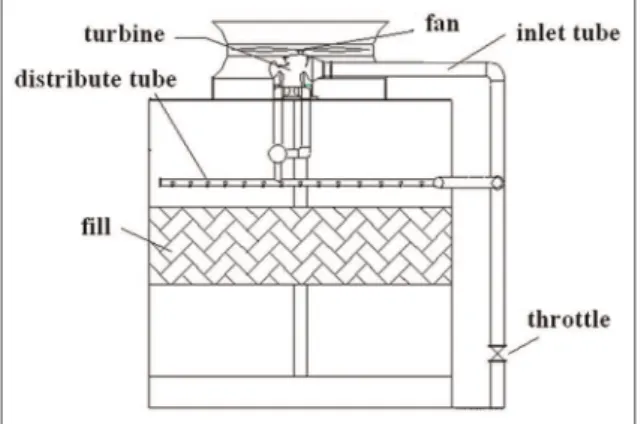
A cooling tower is a heat removal device used to trans-fer waste heat absorbed in the circulating cooling water systems to the atmosphere.1,2 The water contacts the air to dissipate the industrial waste heat. At present, most of the fans used in cooling towers are driven by motors that consume large amounts of electric energy. However in China, water circulating in cooling water systems still keeps a surplus pressure between 39,240 and 147,150 Pa due to an excessive design margin, which is often wasted in the throttle valve. In order to utilize wasted energy, it is suggested that the surplus water energy can be harnessed to drive a type of
hydroturbine installed in the inner platform of cooling tower and make the fan rotate through its coupled shafts, as shown in Figure 1. However, conventional hydroturbines are not suited for this job due to the
1College of Energy and Electrical Engineering, Hohai University, Nanjing,
P.R. China
2College of Water Conservancy and Hydropower Engineering, Hohai
University, Nanjing, P.R. China
Corresponding author:
Daqing Zhou, College of Energy and Electrical Engineering, Hohai University, Nanjing 210098, P.R. China.
Email: [email protected]
operating conditions of cooling towers and fan parameters.
Zhang3 used a Pelton turbine to recover the waste energy of a cooling tower, and his test results showed that the limited installation space of the cooling tower forced the Pelton turbine runners to be entirely sub-merged in water, so that its efficiency decreased greatly. Chen4improved a Pelton turbine used in cooling towers and recommended another turbine type, the Francis turbine. Although a Francis turbine usually has high efficiency, its higher rotating speed does not match with that of the fan and requires a corresponding reducer, which makes the entire device structure complex and large in dimension. Many studies have been carried out to improve the hydraulic performance of Francis tur-bines used in cooling towers,5–8while the efficiency of these turbines was not sufficiently high. Therefore, a new type of hydroturbine should be designed to fit the working conditions of the cooling tower. With the advancement of computer technology and computa-tional fluid dynamics (CFD), more researchers have used CFD methods to analyze the characteristics of the fluid machinery such as pumps and turbines.9–11In this article, a new type of Francis turbine with an ultra-low specific speed was studied and developed through CFD
simulations and experimental methods. It had smaller dimension, high efficiency, and low cost and could meet the need of the cooling tower well.
Basic parameter design
Specific speed
In this study, a new Francis turbine was designed aimed at a given cooling tower, where the discharge of recycled water was 0.833 m3/s and surplus water head was 13 m. The fan installed in this cooling tower rotated at a rated speed of 136 r/min, and the motor power was 91 kW.
The specific speed ns is an important parameter to
classify hydroturbines as to their types and proportions. It is calculated by the following formula
ns=
npffiffiffiP
H5=4 ð1Þ
here,n, P, andHare the rotating speed, output power, and water head of the hydroturbine, respectively. Additionally, the unit speed n11 is another important
parameter and calculated by equation (2)
n11=
nD1
ffiffiffiffi H
p ð2Þ
For a given cooling tower, substituting the para-meters above into equation (1), the ns of the new
Francis hydroturbine is equal to 52.6 mkW, which is very low compared to the conventional Francis hydro-turbines used in power stations. According to the rela-tion between Francis hydroturbine dimensions and specific speed12as well as the limited installation space in the cooling tower, the basic parameters of this new Francis hydroturbine were determined and listed in Table 1.
It is worth mentioning that to reduce the horizontal size of the new Francis hydroturbine, single-row guide vanes, instead of the normal double-row vanes, were used to provide both water diversion and load support-ing. Likewise, the shapes of spiral case sections are all elliptical, and a taper draft tube with a cone angle of 13°was employed.
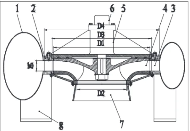
The schematic of the new Francis hydroturbine is shown in Figure 2.
CFD simulation results
Numerical simulation method
Three-dimensional turbulent steady simulation of the Francis turbine was conducted using Fluent 6.2 software.13 For the fluid flow analysis of this turbine, the continuity equation and Reynolds-averaged
Table 1. Basic parameters of the new type of Francis hydroturbine.
Geometrical parameter Symbol Value
Diameter of runner inlet D1(mm) 1040 Diameter of runner exit D2(mm) 520 Diameter of guide vane exit D3(mm) 1070 Diameter of guide vane inlet D4(mm) 1240 Height of guide vane b0(mm) 90
Number of guide vanes Z1 17
Number of runner blades Z2 17
Navier–Stokes equation for steady incompressible flow were used in the following form
∂Ui
∂Xi =0 ð3Þ
Uj
∂Ui
∂Xj +
1
r ∂p
∂Xi ∂
∂Xi y ∂Ui
∂Xj + ∂Uj
∂Xi
tij
=0 ð4Þ
where U, p, y, and r are the velocity, pressure,
kine-matic viscosity, and density, respectively, andtij is the
component of the viscous stress tensor, also called the Reynolds stress tensor. The turbulent effects on the flow field are through the Reynolds stressestij, which
were calculated from the Spalart–Allmaras turbulence model14adopted in this article for its better numerical convergence and robustness.15The governing equations are discrete with finite volume method, and the second-order central difference format is used for the diffusion item, and the second-order upwind format is used for the convection item, and the Semi-Implicit Method for Pressure-Linked Equations–Consistent (SIMPLEC)
method is adopted to realize the velocity pressure cou-pling solution. The boundary conditions were set as fol-lows: for the inlet boundary condition, the relative total pressure, turbulent kinetic energy, and its diffusion rate were given; for the outlet boundary condition, the rela-tive static pressure, turbulent kinetic energy, and its dif-fusion rate were prescribed; no-slip boundary condition was applied to the wall; and standard wall functions were applied to the region near the wall.16
With the considerations of the grid sensitivity and the personal computer’s (PC) computing capability, unstructured tetrahedron elements were chosen and built by Gambit meshing software.17 The mesh inde-pendence was also checked as shown in Table 2. We found that when the total number of meshes exceeded 2.59 million, the result was more or less independent of the mesh refinement for schemes 4 and 5.
Therefore, the results from mesh scheme 4 were used to perform the analysis, and the mesh number of each turbine passage part is shown in Table 3.
Numerical results of the initial scheme
Through three-dimensional steady simulation, it was found that the discharge Q was equal to 0.845 m3/s and the torqueMwas 6436 N m when the water head
Hwas set as 13 m and n= 136 r/min. Then, the effi-ciency h=85% and power P= 91.6 kW were
obtained, and the total pressure in every flow section was calculated by the area-weighted average method, reported in Table 4.
Hydraulic loss in the turbine passage can also be cal-culated with the following formula
Hydraulic loss =ðPinletPoutÞ
rg ð
5Þ
herein, (Pinlet2 Pout) is the total pressure difference
between the passage inlet and outlet, andr and gare
the water density and acceleration of gravity,
Figure 2. Schematic of the new type of Francis hydroturbine. 1: spiral case; 2: stand ring; 3: guide vanes; 4: runner; 5: bearing block; 6: shaft; 7: draft tube; 8: landing leg.
Table 2. Test of mesh independence.
Scheme 1 Scheme 2 Scheme 3 Scheme 4 Scheme 5
Mesh number 1,304,852 1,795,527 2,193,285 2,587,678 3,064,526
Efficiency (%) 84.51 84.75 84.90 85.00 84.98
Table 3. Mesh number of each part of the turbine.
Casing Guide vane Runner Draft tube
Mesh number 358,180 422,015 1,379,824 427,657
respectively. From Table 4, it can be found that hydraulic loss mainly exists in the guide vanes region and reaches 10.5%, that is, 1.41 m.
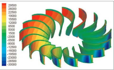
The inner flow fields of initial scheme are described to reveal the characteristics of the ultra-low specific speed turbine. Figure 3 shows that the static pressure decreases gradually and clearly from the leading edge to the trailing edge on the blade’s pressure side, and localized low pressure appears near the leading edge of blade’s suction side, which is caused by the high velo-city developed between the guide vanes and runner blades, illustrated in Figure 4. Figure 4 also displays that the velocity in the runner inlet region is generally high with the maximum velocity more than 17 m/s, which demonstrates kinetic energy to be the main form of energy acting on the runner blades. From Figure 5, it can be concluded that the flow pattern in the runner is uniform because streamlines of relative velocity dis-tribute smoothly in the blade-to-blade channel.
Numerical results of an improved scheme
Although the turbine power of the initial scheme can meet the power requirement of the fan, the deficiency is also clear for its exceeded discharge and excessive hydraulic loss in the guide vanes region. Therefore, an
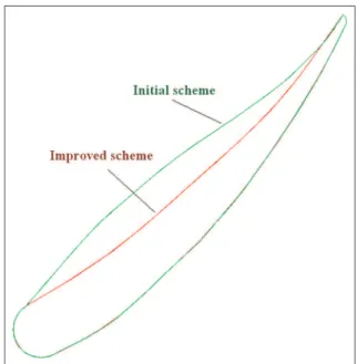
improved scheme was designed through shape modifi-cation for both the guide vanes and the runner blades, shown in Figures 6 and 7. In terms of the improved scheme, one side of the guide vane profile was adjusted to make it slender, and the airfoil bending angularity of the runner blade was increased simultaneously.
Through CFD simulation, the parameters of the improved scheme were obtained as follows: discharge
Q= 0.835 m3/s, torque M= 6620 N m, efficiency
h = 88.5%, and powerP= 94.2 kW. The total
pres-sure in every flow section was also calculated and listed in Table 5.
According to Table 5, the hydraulic loss in the guide vane region is reduced to 7.4% because the value of the absolute velocity decreases by nearly 0.5 m/s for the wider guide vane channel when comparing Figure 8 with Figure 9.
The peripheral speed of the draft tube entrance is more obvious in Figure 10. However, it almost disappears in Figure 11 due to the increased airfoil bending angularity of the runner blade, which is also beneficial to the reduc-tion of hydraulic loss for low specific speed turbines.18
Experimental measurements
The ultra-low specific speed Francis turbine was manu-factured according to the improved scheme. Experiments have been performed in the test rig of hydraulic machinery through changing water head from 5 to 16.5 m under a constant rotating speed of 136 r/min (Figure 12). Test results showed that the maximum efficiency reached 88%, as well as
H = 11.6 m andQ= 0.794 m3/s, which was 0.5% less than that of the CFD results. When H= 12.66 m and
Q= 0.848 m3/s, the turbine could produce 91 kW of power.
Table 4. Total pressure in every flow section.
Flow section Total pressure (Pa)
Spiral case inlet 132,435
Spiral case exit (guide vane inlet) 130,522 Guide vane exit (runner inlet) 116,681 Runner exit (draft tube inlet) 5562
Draft tube exit 5229
Figure 13 shows that the efficiency of CFD results agrees well with that of test results between n11 = 39
and 43 r/min, and the best efficiency point of the test results shifted right toward larger n11 values because
the surface roughness of the turbine passage was found larger than normal by inspection.
Overall, the Francis turbine with ultra-low specific speed was proven to be capable of completely replacing the motor to drive the fan, achieving the goal of utiliz-ing renewable energy in the coolutiliz-ing tower.
Conclusion
1. Through CFD simulations and experimental tests, an ultra-low specific speed Francis turbine was developed, which can completely replace the motor to drive the fan for its high efficiency, achieving the goal of utilizing renewable energy in cooling towers.
Figure 4. Absolute velocity vector field in the horizontal cross-section located in the half height guide vane (m/s).
Figure 5. Streamlines of relative velocity in runner blades’
Figure 7. Runner blade shape comparison between the two schemes.
Table 5. Total pressure in every flow section for the improved scheme.
Flow section Total pressure (Pa)
Spiral case inlet 132,435
Spiral case exit (guide vane inlet) 130,591 Guide vane exit (runner inlet) 120,830 Runner exit (draft tube inlet) 5497
Draft tube exit 5270
Figure 8. Absolute velocity contours in the guide vane-to-vane channel of the initial scheme (m/s).
Figure 9. Absolute velocity contours in the guide vane-to-vane channel of the improved scheme (m/s).
Figure 10. Streamlines of absolute velocity in the draft tube entrance section of the initial scheme.
Figure 11. Streamlines of absolute velocity in the draft tube entrance section of the improved scheme.
2. Most of the hydraulic loss was found in the guide vane region. Therefore, further optimiza-tion of the guide vanes should be done for tur-bine performance improvement.
3. The high flow velocity in the guide vane region and long-narrow shape runner blades cause the passage surface roughness to be one of the cru-cial factors affecting turbine efficiency.
Acknowledgements
The support of College of Energy and Electrical Engineering, Hohai University, China, is gratefully acknowledged.
Declaration of conflicting interests
All authors declare that there is no conflict of interest regard-ing the publication of this article. All authors do not have a direct financial relation with the commercial identities men-tioned in this article that might lead to a conflict of interest for any of the authors.
Funding
The research work was funded by Chinese National Foundation of Natural Science (No. 51106042).
References
1. Zhao Z. The cooling tower. Beijing, China: Water & Power Publishing House, 2001.
2. Tan Y. Development and present state of study on cool-ing tower technology. Refrig Air Condition 2013; 27: 494–498.
3. Zhang F. Mini-hydraulic turbine applied in cooling towers.Ind Water Treat2004; 24: 57–59.
4. Chen M. Research and design on a new kind of energy-saving turbine replacing motor for radiator fan inside cool-ing tower. Master Dissertation, Hohai University, Nanj-ing, China, 2007.
5. Zhang L, Zheng Y, Zhou D, et al. Study on a Francis turbine with super-low specific speed applied in cooling towers. In: ASME 2010 international mechanical
engineering congress and exposition—IMECE 2010, Van-couver, BC, Canada, 12–18 November 2010, vol. 7, parts A and B, pp.755–759. New York: ASME.
6. Zhang L, Wang L and Ren Y. Characteristic analysis of Francis-turbine in cooling tower.Appl Mech Mater2012; 190–191: 57–59.
7. Ruan H, Luo XQ, Liao WL, et al. Hydraulic design of a low-specific speed Francis runner for a hydraulic cooling tower. In:26th IAHR symposium on hydraulic machinery and systems, IOP Conf. Series: Earth and Environmental Science, Beijing, China, 19–23 August 2012, vol. 15, part 3, p.032011. Bristol: IOP Science Publishing.
8. Li Y, Nan H and Chen D. Performance and type selec-tion of special hydraulic turbine in cooling tower. J Hydroelectr Eng2011; 30: 175–179.
9. Wang F, Li Y and Wang W. Analysis on CFD applica-tion in water pumps.Drain Irrig Mach2005; 23: 1–10. 10. Anagnostopoulos JS. CFD analysis and design effects in
a radial pump impeller.WSEAS Trans Fluid Mech2006; 1: 763–770.
11. Hellstro¨m JGI, Marjavaara BD and Lundstro¨m TS. Par-allel CFD simulations of an original and redesigned hydraulic turbine draft tube. Adv Eng Softw 2007; 38: 338–344.
12. Zheng Y, Ju X and Chen Y.Turbine. Beijing, China: Sci-ence and Culture Publishing House, 2003.
13. Fluent Inc.Fluent manual 6.2(technical reference). Leba-non, NH: Fluent Inc., 2005.
14. Spalart PR and Allmaras SR. A one-equation turbulence model for aerodynamic flows.Rech Aerospatiale1994; 1: 5–21.
15. Zheng Y, Liu J, Chen Y, et al. Numerical simulation of tubular pump based on Fluent.J Drain Irrig Mach Eng
2010; 28: 233–237.
16. Chen Y, Zhou D, Li L, et al. Numerical simulation and hydrodynamics optimization of direct-drive Francis tur-bine runner in cooling towers. J Drain Irrig Mach Eng
2014; 32: 600–605.
17. Li J, Yu J and Wu Y. 3D unsteady turbulent simulations of transients of the Francis turbine. In:25th IAHR sym-posium on hydraulic machinery and systems, IOP Conf. Series: Earth and Environmental Science, Timisxoara, 20–24 September 2010, vol. 12, p. 012001. Bristol: IOP Science Publishing
18. Susan-Resiga R, Ciocan GD, Anton I, et al. Analysis of the swirling flow downstream a Francis turbine runner.J Fluid Eng Trans ASME2006; 128: 177–189.
Appendix 1
Notation
b0 height of guide van
D1 inlet diameter of runner
D2 outlet diameter of runner
D3 diameter of guide vane exit
D4 diameter of guide vane inlet
g acceleration of gravity
H water head
n the runner rotating speed
ns specific speed
n11 unit speed
M torque
p pressure
P power of the turbine
Q discharge
U velocity
h turbine efficiency r water density
tij Reynolds stress tensor