ARTIGO ORIGINAL
Estudo mecânico de implante para fixação do segmento
lombossacro da coluna vertebral
Mechanical study of implant for lumbossacral spinal fixation
A
FRANES
ERDEIRA11111;;;;; T
ARCÍSIOE
LOYP
ESSOADEB
ARROS F
OOOOO22222; E
DUARDODEB
ARROSP
UERTAS33333;;;;;
J
OSÉL
AREDOF
ILHO 4 4 4 4 4; T
OMAZP
UGAL
EIVAS 5 5 5 5 5RESUMO
Foram estudados, do ponto de vista mecânico, a rigidez e os pontos críticos de um implante para fixação interna da coluna lombossacra.
Aplicou-se o implante sobre um modelo de madeira simulando o segmento lombossacro da coluna. Realizamos sete ensaios de flexo-compressão, sete de rigidez axial, sete de rigidez radial e um ensaio destrutivo. Os resultados demonstraram que o implante foi eficiente e seguro para uso em seres humanos.
Descritores: Coluna vertebral - artrodese; Fusão espinal; Implantes artificiais; Instabilidade articular.
SUMMARY
This work consists of a mechanical analysis of the resistance and critical points of a stainless steel device for lumbossacral spinal fixation. The device was fixed into a wooden model representing the spinal lumbossacral segment. The experiment comprised seven tests of flexo-compression, seven tests of axial rigidity, seven tests of radial rigidity, and one destructive test.
The critical points are the intersection of the pedicular screws threads and the attrition rate between the vise and the rod. The results demonstrated the device to be efficient and safe when used in human beings.
Key words: Vertebral spine - arthodesys; spine fusion; Artificial implants; Articular instability.
INTRODUÇÃO
Desenvolvemos um implante constituído por uma haste em forma de “U”, que funciona como barra de fixação de parafusos pediculares e que permite uma montagem tridimensional que denominamos de A-S1 (implante A Série 1).
O objetivo deste trabalho é, através de simulações biomecânicas em modelo estandardizado de coluna lombossacra submetida a esforços de flexocompressão, determinar a estabilidade axial e radial, os limites de elasticidade e de resistência, assim como os pontos críticos do implante proposto para fixação interna do segmento lombossacro.
Dissertação de Mestrado (resumo) apresentada à Escola Paulista de Medicina na área de Ortopedia e Traumatologia e no LIM-41 do Inst. de Ortop. e Traumatol. do Hosp. das Clínicas da Fac. de Med. da Univ. de São Paulo.
1. Doutor pela EPM e Assistente do Serviço de Ortopedia e Traumatologia do Hospital São Lucas da PUCRS
2. Professor Associado e Livre-docente do Instituto de Ortopedia e Traumatologia da FMUSP, Grupo de Coluna e Trauma Raquimedular do Hospital das Clínicas da USP. 3. Doutor pela Escola Paulista de Medicina, Chefe do Grupo de coluna do Depto. de Ortopedia e Traumatologia da EPM.
4. Professor Titular e Chefe do Depto. de Ortopedia e Traumatologia da EPM. 5. Engenheiro Chefe do Latoratório de Biomecânica LIM-41 do IOT-HC-FMUSP
INTRODUCTION
We developed an implant composed by a shaft with “U” shape, that works as a fixation barr of pedicular screws which allows the assemblage of tridimensional model we called A-S1 (Implant a Series 1).
The objective of this work is, using biomechanical simulations in standardized model of lumbossacral spine submitted to efforts of flexocompression, determine the axial and radial stability, the limits of elasticity and resistence, as well as the critical points of the proposed implant for internal fixation of the lumbossacral segment.
MATERIAL E MÉTODOS
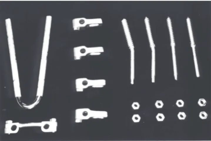
O dispositivo de fixação é composto das seguintes partes: (Fig. 1)
1. Haste formada por uma barra de aço inoxidável ASTM EF 138, com dureza de 38 HRC e secção de 6,4 mm (1/4 polegada) de diâmetro dobrada em “U”, com 110 mm de comprimento.
2. Quatro parafusos pediculares com rosca óssea esponjosa (tipo dente de serra)
3. Quatro grampos de fixação, compostos de duas garras contrapostas, que são oselementos de ligação entre a haste e o parafuso, formando uma montagem tridimensional 4. A barra ou ponte antitorção mantém o afastamento entre os
“braços” da baste, transformando-a em um retângulo rígido.
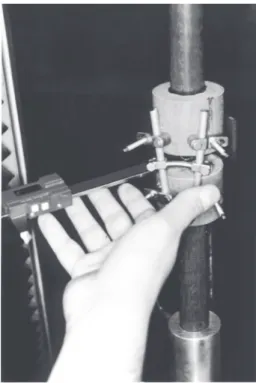
O MODELO DE COLUNA (Fig. 2)
Com base no trabalho de TOLEDO (1989), usamos um modelo de coluna lombossacra, composto de dois segmentos em madeira de Ipê, suficientemente dura e homogênea, permitindo a colocação dos parafusos e suportando as cargas sem alterações.
MÉTODOS
O modelo experimental procurou avaliar o efeito de cargas de compressão excêntricas (não axiais) sobre corpos vertebrais lombossacros (L5-S1) estabilizados pelo fixador, respeitando a geometria da montagem (forma, ângulos e distâncias) e as características biomecânicas locais.
FIGURA 1 – Implante desmontado
Neste trabalho adotamos, como parâmetro inicial para análise da rigidez axial e radial, 100 Kgf de carga máxima de flexo-extensão que corresponde a pacientes com 80 Kg de peso em posição ortostática.
FIGURA 2 – Modelo experimental
MATERIAL AND METHODS
The fixation device is composed of the following parts: (Fig. 1) 1. Shaft of stainless steel ASTM EF 138, with hardness of 38 HRC and diameter section of 6,4 mm (1/4 inch) bented in “U”, 110 cm long.
2. Four pedicular screws with spongiosus screw thread (sew type) 3. Four fixation staples, comprised of two counterplaced clinches, which are the elements of union between the shaft and the screw, forming a tridimensional model.
4. The barr keeps the distance between the “arms” of the shaft, making it a rigid retangle.
SPINE TEMPLATE (Fig. 2)
Based on work of TOLEDO (1989), we used a model of lumbossacral spine, constructed with two segments of wood ipê, hard enough and homogeneous to permit placement of screws and bearing the loads without alterations.
METHODS
The experimental model aimed the evaluation of the effect of eccentric (non-axial) compression loads over lumbossacral vertebral bodies (L5-S1) stabilized by the fixator, respecting the geometry of the model (shape, angles and distances) and the local biomechanical characteristics.
In this work we accepted, as initial parameter for the analysis of the axial and radial hardness, 100 Kgf of maximum load for flexion-extension what corresponds to patients with 80 Kg of weight in orthostatic position.
FIGURA 3 – Máquina universal de ensaios do LIM-41
FIGURE 3 – Universal machine for tests of LIM-41
FIGURA 4 – Ensaio para determinação da rigidez axial
FIGURE 4 – Tests for determination of axial rigidity
FIGURA 5 – Diagrama do teste
FIGURE 5 – Diagram of the test O implante foi montado paralelo na parte posterior do sistema, contraposto a uma articulação taça-esfera, mantendo 20 mmde espaçamento entre os discos.
Os parafusos pediculares foram colocados a uma distância entre si, como ocorre “in vivo”, equivalente à distancia entre os pedículos do mesmo corpo vertebral .
ENSAIOS DE FLEXOCOMPRESSÃO
The implant was mounted parallel in the posterior part of the system, opposed to one articulation cup-spheric, keeping 20 mm of space between the disks.
The pedicular screws were placed with a distance between them, as it occurs “in vivo”, equivalent to the distance between the pedicles of same vertebral body.
FLEXO-COMPRESSION TESTS
ENSAIO PARA DETERMINAÇÃO DA RIGIDEZ RADIAL (FUGA LATERAL MÁXIMA)
Foram realizados sete ensaios de flexocompressão, aplicando-se cargas seqüenciais progressivas de zero (posição inicial) a 100 Kgf, de 20 em 20 Kgf, a cada incremento de carga (fig.6). .Essas medidas foram anotadas em planilhas para posterior análise
FIGURA 6 – Ensaio para determinação da rigidez radial
FIGURE 6 – Test to determine the axial rigidity
FIGURA 7 - Ensaio destrutivo
FIGURE 7 – Destructive test
Os ensaios de flexocompressão foram realizados em máquina universal de ensaios mecânicos Kratos K5002. A velocidade de aplicação da carga compressiva foi de 20 mm/min para os ensaios de determinação de rigidez axial e radial (fuga lateral máxima) e de 10 mm/min para o destrutivo.
ENSAIOS PARA DETERMINAÇÃO DA RIGIDEZ AXIAL
Foram realizados sete ensaios de flexocompressão, aplicando carga contínua de zero a 100 Kgf ao modelo, obtendo os respectivos diagramas de força de compressão-deformação axial (pistonamento) (Fig. 4 e 5).
The flexo-compression tests were performed in a universal machine for mechanical tests, Kratos K5002. The speed of application of the compressive load was 20 mm/min for the tests to determine axial and radial rigidity and of 10 mm/min for the destructive.
TESTS FOR DETERMINATION OF AXIAL RIGIDITY
Seven tests of flexo-compression were performed, with use of continuous load from zero to 100 Kgf to the model, to obtain the respective diagrams of strength of axial compression-deformation (Fig. 4 and 5).
TEST FOR DETERMINATION OF THE RADIAL RIGIDITY
116
ANÁLISE DOS DIAGRAMAS E PLANILHAS ANÁLISE DOS DIAGRAMAS E PLANILHAS ANÁLISE DOS DIAGRAMAS E PLANILHAS ANÁLISE DOS DIAGRAMAS E PLANILHAS ANÁLISE DOS DIAGRAMAS E PLANILHAS
Analisamos a rigidez axial do implante através da observação de diagramas carga-deformação obtidos nos ensaios de flexocompressão (Fig 5). No diagrama carga-deformação do ensaio destrutivo (Fig 9), determinou-se os seguintes pontos :
a - limite de elasticidade
b - limite de resistência à flexocompressão.
O limite de elasticidade corresponde ao fim da fase linear do diagrama e representa a carga e deformação, máximas, a qual o implante pode suportar sem apresentar qualquer dano, desligamento ou deformação permanente (residual) após a descompressão, segundo SOUZA (1982) E CHIAVERINI (1986). As medidas radiais foram realizadas por paquímetro digital Mitutoyo Digimatie Caliper 500- 21 5 (0,01 mm), com carregamento de zero, 20, 40, 60, 80 e 100 Kgf (flexocompressão).
Esses dados foram transferidos para planilhas computadorizadas que realizaram os cálculos do movimento espacial.
FIGURA 8 – Implante desmontado após o teste destrutivo
FIGURE 8 – Dismounted implant after the destructive test
ENSAIO DESTRUTIVO PARA DETERMINAÇÃO DOS LIMITES DE ELASTICIDADE E DE RESISTÊNCIA, E IDENTIFICAÇÃO DOS PONTOS CRÍTICOS
Os limites de elasticidade e resistência foram determinados em ensaio destrutivo de flexocompressão com carga contínua registrado graficamente, que permitiu a identificação dos pontos críticos. (Fig. 7). Após o ensaio o implante foi desmontado e inspecionado cuidadosamente (inspeção visual do implante desmontado) para confirmação das falhas (fig. . . 8).
DESTRUCTIVE TEST FOR DETERMINATION OF THE LIMITS OF ELASTICITY AND RESISTANCE, AND IDENTIFICATION OF CRITICAL POINTS
The limits of elasticity and resistance were determined in a destructive test of flexo-compression with continuous load graphically registered, what allowed the identification of the critical points (Fig. 7). After the test the implant was dismounted and inspected carefully for confirmation of failures (fig. . . . . 8).
ANAL ANAL ANAL ANAL
ANALYSIS OF DIAGRAMS AND DAYSIS OF DIAGRAMS AND DAYSIS OF DIAGRAMS AND DAYSIS OF DIAGRAMS AND DAYSIS OF DIAGRAMS AND DATTTTTAAAAA
We analyzed the axial rigidity of the implant in the diagrams load-deformity obtained in the tests of flexor-compression (Fig 5). In the diagram of load-destruction of the destructive test (Fig. 9), the following points were found:
a – limit of elasticity
b – limit of resistance to flexo-compression
The limit of elasticity correspond to the end of the linear phase of the diagram and represents the maximum load and deformation, that the implant can support without presenting any damage ou permanent deformation (residual) after decompression, according to SOUZA (1982) and CHIAVERINI (1986). The radial values were taken with pachimeter digital Mitutoyo Digimatic Caliper 500- 21 5 (0,01 mm), with load from zero to 20, 40, 60, 80 e 100 Kgf (flexo-compression).
MÉTODO ESTATíSTICOS
Os dados obtidos nos ensaios mecânicos foram analisados estatisticamente.
RESULTADOS
Os resultados obtidos nos ensaios se encontram expressos nas tabelas de 1 a 6. O formulário para coleta de dados usado nos ensaios e os valores foram transferidos para as planilhas computadorizadas, com as quais foram realizados os cálculos. O deslocamento axial médio (pistonamento) observado após a aplicação de 100 Kgf. em flexocompressão foi de 3,52 mm (Tab. 1 e 2), o que corresponde a 7% de encunhamento da altura do corpo vertebral (50 mm) do modelo adotado. Encurtamentos de 7% estão dentro de limites toleráveis que não provocam danos à cauda equina nem aos ligamentos posteriores da coluna responsáveis pela estabilização do segmento.
Tab. 1 – Resultados gerais e valores excluídos para análise estatística obtidos nos ensaios de estabilidade axial e radial em
flexocompressão.
Ensaio de estabilidade axial Ensaio de estabilidade radial
Deslocamento Rigidez Fuga lateral máxima
Mm (10-3
m) % Kgf/mm 105
N/m Mm (10-3
m)
1 3,60 7,20 27,78 2,72 2,73
2 3,20# 6,40# 31,25+ 3,06+ 2,75
3 3.60 6,80 29,41 2,88 2,88
4 3,60 7,20 27,78 2,72 2,96+
5 3,60 7,20 29,78 2,72 2,49
6 3,40 6,80 29,41 2,88 2,47#
7 3,80+ 7,60+ 26,32# 2,58# 2,55
Resultados extremos excluídos para análise estatística + valor máximo
# valor mínimo
FIGURA 9- Diagrama carga-deformação
FIGURE 9- Diagram load-deformation O máximo distanciamento entre os ponteiros (fuga lateral),
foi observado após a aplicação seqüencial das cargas. A “fuga lateral máxima” representa o maior deslizamento radial entre os segmentos, responsável pela tendência de cisalhamento in vivo.
The maximum distance between pointers (lateral movement), was observed after sequential application of loads. The “maximum lateral movement” represents the bigger radial sliding between the segments, responsible for the problem “in vivo”.
STATISTICAL METHODS
The data obtained in the mechanical tests were statistically analysed.
RESULTS
The results of the tests are presented in Tables 1 to 6. The form for data collection and the values were transferred to computerized tables, and calculations were performed. The average axial displacement observed after 100 Kgf. of flexo-compression was 3,52 mm (Table. 1 e 2), what correspond to 7% of wedge shaping of the vertebral body (50 mm) in the adopted model. Shortenings of 7% are within the tolerated limits which do not harm the spinal cord nor posterior ligaments of the spine, responsible by the segment stability.
Test of axial stability Test of radial stability
Displacement Rigidity Maximum lateral movement
Mm (10-3
m) % Kgf/mm 105
N/m Mm (10-3
m)
1 3,60 7,20 27,78 2,72 2,73
2 3,20# 6,40# 31,25+ 3,06+ 2,75
3 3.60 6,80 29,41 2,88 2,88
4 3,60 7,20 27,78 2,72 2,96+
5 3,60 7,20 29,78 2,72 2,49
6 3,40 6,80 29,41 2,88 2,47#
7 3,80+ 7,60+ 26,32# 2,58# 2,55
Extreme results were excluded from the statistical analysis + maximum value
# minimum value
Table. 1 – Global results and excluded values from the statistical analysis, obtained in the tests of axial and radial stability after
118
Tab. 2 – Deslocamento axial ou pistonamento do implante, em mm (10-3m) submetido a flexocompressão.
Tab. 2 – Axial displacement of the implant in mm (10-3m) submitted to
flexo-compression
Deslocamento axial
Axial displacement
Mm (10-3 m) %
1 3,60 7,20
2 3,40 6,80
3 3,60 7,20
4 3.60 7,20
5 3,40 6,80
N 3,52 7,04 DP 0,11 0,22 EPM 0,05 0,10
CV 3,11 3,11
Tab. 3 – Rigidez axial, em kgf e N/m, do implante submetido à flexocompressão.
Tab. 3 – Axial rigidity, in Kgf and N/m, of the implant submitted to flexo-compression
Deslocamento axial
Axial displacement
Kgf/mm 105 N/m 1 27,78 2,72 2 29,41 2,88 3 27,78 2,72 4 29,78 2,72 5 29,41 2,88 N 28,43 2,78 DP 0,89 0,09
EPM 0,40 0,04
CV 3,14% 3,15%
A Tabela 3 mostra as cargas necessárias para obtermos 1 mm de deformação axial, e nos permite avaliar a movimentação máxima que pode ocorrer em pacientes, conhecendo seu peso corpóreo.
Na Tabela 4 observamos uma fuga lateral (cisalhamento) de 2,68 mm sob uma carga de flexocompressão de 100 kgf., na prática utilizam-se valores em torno de 1 mm como ideais para sistemas de fixação interna. Os valores obtidos são superiores mas não suficientes para comprometer mecanicamente a sua aplicação.
Tab. 4 – Fuga lateral máxima do implante submetido a flexocompressão em mm (10-3 m).
Tab. 4 – Maximum lateral movement of the implant submitted to flexo-compression in mm (10-3 m)
Fuga lateral máxima
Maximum lateral movement
Mm (10-3 m) 1 2,88 2 2,49 3 2,55 4 2,73 5 2,75 N 2,68 DP 0,16 EPM 0,07 CV 5,91% Nos resultados do ensaio destrutivo observamos uma falha
de fixação, com escorregamento entre a haste e grampo com 185 Kgf no limite da elasticidade (tabela 5).
Aos 260 Kgf, limite da resistência, ocorreu a deformação dos parafusos pediculares na transição entre as roscas (tabela 6).
Tab. 5- Determinação do limite de elasticidade do implante subme-tido a ensaio destrutivo de flexocompressão (resistência em kgf e
N e a deformação em mm= 10-3m e %)
Limite de elasticidade
Elasticity limit
Resistência
Resistance
Deformação
Deformity
Kgf N Mm(10-3 m) %
185 1813 6,18 12,35
Causa da falha: escape ou deslizamento entre o grampo (conector) e a haste.
Cause of failure: scape or sliding between the staple (conector) and shaft.
Tab. 6 - Determinação do limite de resistência do implante subme-tido a ensaio destrutivo de flexocompressão (resistência em kgf e
N, e a deformação em mm= 10-3m e %)
DISCUSSÃO
Com melhores conhecimentos da biomecânica da coluna e de materiais adequados houve incessante desenvolvimento dos implantes de fixação interna para coluna lombossacra (HANLEY, PHILLIPS, KOSTUYK, 1991)8. O instrumental de HARRINGTON (1962)9 tem uso limitado nas patologias degenerativas, pois existem dificuldades para implantar o grampo distal no sacro. Outro problema que ocorre com as hastes de distensão é a retificação da lordose lombar (distensão posterior). A haste de Luque tem seu uso mais amplo, principalmente nas escolioses, cifoses, fraturas, tumores e em espondilolisteses degenerativas. Entretanto são ineficientes para opor-se às forças de compressão, extensão e rotação. BARROS Fo ( 1987 )1, aplicando a técnica de Harrington-Luque, baseado em trabalho anterior(
Table 3 shows the necessary loads to obtain 1 mm of axial deformity, and permits evaluate the maximum movement that could occur in patients, once his/her body weight is known
In Table 4 we observe lateral movement of 2,68 mm under of flexo-compression load of 100 kgf. In practice values around 1 mm are used as ideal for systems of internal fixation. The values obtained are superior but not sufficient to compromise mechanically its application.
In the results of the destructive test we see a failure of fixation, with sliding between the shaft and staple with 185 Kgf in the limit of elasticity (Table 5)
Tab. 5- Determination of elasticity limit of the implant under destructive test of flexo-compression (resistence in Kgf and N and deformity in mm=
10-3m and %)
With 260 Kgf, limit of resistance, occurred a deformity of the pedicular screws in the transition between the screw threads (Table 6).
Tab. 6 – Determination of resistance limit of the implant submitted to destructive test of flexo-compression (resistance in Kgf and N and the
deformity in mm= 10-3m and %)
Limite de elasticidade Elasticity limit Resistência
Resistance
Deformação Deformity
Kgf N M m(10-3 m) %
BASILE, 1985 )2 , verificou tratar-se de um método eficiente quando associado à fixação segmentar com amarrilhos sublaminares de Luque..
Foi ROY-CAMILLE (1986)16 quem desenvolveu o primeiro método prático de fixação com parafuso pedicular e uma placa. Neste método, se houver reabsorção óssea ou compressão sob a placa, vão ocorrer movimentos entre os orifícios da placa e os parafusos, ocasionando a fadiga do material seguida de ruptura destes. STEFEE et al. (1986)18 para solucionar o problema colocaram os parafusos perpendicularmente à placa, porém como esta é rígida, nem sempre conseguiram que os parafusos penetrassem perpendicularmente, o que provocava uma força de flexão no parafuso, que então se rompia. KRAG (1991)11 estudou vários sistemas de fixação interna ( Wiltse, Zielke, -Cotrell-Dubousse, Puno e outros modelos ) que empregam uma peça intermediária entre o parafuso e a barra ou fixam o parafuso diretamente à barra longitudinal, nenhum deles, leva em consideração o desalinhamento do eixo longitudinal entre os parafusos , e da inclinação deles em relação à barra. Uma análise biomecânica entre os sistemas pediculares e as técnicas de Galveston e Luque foram apresentadas por PUNO et al.(1991)15. Os ensaios mecânicos mostraram que a rigidez da fixação pedicular era intermediária entre as técnicas referidas. BLUMENTHAL & GILL (1993)3 avaliaram um grupo de 470 pacientes que foram submetidos a artrodese lombar e instrumentação com implante de Wiltse. Usaram múltiplas configurações do sistema de Wiltse em 95% das cirurgias, aplicaram o parafuso pedicular preso à haste com um grampo intermediário. Ocorreram complicações em 29 pacientes (6,17%). Podemos deduzir a partir destes dados, que, com as montagens tridimensionais que usam grampo intermediário, o número de complicações com implante é muito pequeno. A comparação deste implante em relação aos que foram pesquisados pode ser resumida como: rigidez suficiente para suportar as solicitações mecânicas da coluna vertebral, tanto quanto nos sistemas de LUQUE et al (1982)12., de HARRINGTON com amarrilhos sublaminares (BARROS FILHO, 1987)1 de ROY-CAMILLE et al. (1986)16 , de STEFEE et al. (1986)18, de WILTSE (1991)21 e de PUNO et al. (1991)15. Não encontramos nenhum trabalho com as mesmas características para a realização de um estudo comparativo. O deslocamento axial médio (pistonamento) observado após a aplicação de 100 Kgf. em flexocompressão foi de 3,52 mm. (Tab. 2), o que corresponde a 7% de encunhamento da altura (50 mm.) do corpo vertebral do modelo que adotamos. É uma situação que simula a coluna vertebral estabilizada apenas pelo implante, sem a participação das estruturas biológicas (contato ósseo, tensão de partes moles , etc.), que em um modelo reflete situações mais extremas do que normalmente ocorrem na realidade. Encurtamentos de 7% estão dentro de limites toleráveis que não provocam danos à cauda eqüina nem aos ligamentos posteriores da coluna responsáveis pela estabilização do segmento.
A Tabela 3 mostra as cargas necessárias para obtermos 1 mm. de deformação axial, e nos permite avaliar a movimentação máxima que pode ocorrer em pacientes , conhecendo seu peso
DISCUSSION
With better knowledge of the spine biomechanics and adequate materials there was great development of the implants for lumbosacral internal fixation (HANLEY, PHILLIPS, KOSTUYK, 1991)8. The devices from HARRINGTON (1962)9 have limited use
in the degenerative pathologies, since there are difficulties to implant the distal staple in the sacrum. Another problem of the distension shafts is the retification of the lumbar lordosis (posterior distension) The Luque’s shaft has broader use, mainly in the scoliosis, kifosis, fractures, tumors and degenerative spondilolistesis. However, they are not efficient to counteract the strengths of compression, extension and rotation. BARROS Fo (
1987 )1, using the technique of Harrington-Luque, with base in a
former report ( BASILE, 1985 )2 , verified that this was na efficient
method when associated to segmentar fixation with sublaminar strings of Luque. ROY-CAMILLE (1986)16 developed the first
practical method of fixation with pedicular screw and one plaque. In this method, if occurs bone reabsortion or compression under the plaque, movements will occur between the plaque orifices and the screws, causing aging of the material followed by rupture of them. STEFEE et al. (1986)18 to solve the problem placed screws
perpendicular to the plaque, however, as the plaque is rigid, not always succeed to place the screws in perpendicular position, what caused a flexion load in the screw, with consequent rupture. KRAG (1991)11 studied several internal fixation systems ( Wiltse,
Zielke, -Cotrell-Dubousse, Puno and other models) employing na intermediate part between the screw and the barr or fix the screw directly to the longitudinal barr, but none of them, takes into consideration the lack of alignment of the longitudinal axis between the screws and its inclination in relation to the barr. A biomechanical analysis of the pedicular systems and the techniques of Galveston and Luque were presented by PUNO et al.(1991)15. The mechanical
tests could show that the rigidity of the pedicular fixation was between the quoted techniques. BLUMENTHAL & GILL (1993)3
evaluated a group of 470 patients that underwent a lumbar arthrodesis and instrumentation with implant of Wiltse. They used multiple configurations of the Wiltse system in 95% of the surgeries and placed the pedicular screw to the shaft with an intermediate staple. Complications were present in 29 patients (6,17%). We can conclude, considering these data, that with tri-dimensional assemblage that use intermediate staple, the number of complications with implant is very low. Comparing this implant with others we can say that: enough rigidity to support the mechanical loads of the spine, as much as in the systems of LUQUE et al (1982)12., de HARRINGTON (BARROS FILHO, 1987)1
of ROY-CAMILLE et al. (1986)16 , of STEFEE et al. (1986)18, of
WILTSE (1991)21 and of PUNO et al. (1991)15. The average axial
corpóreo.
A rigidez radial é avaliada através da fuga lateral máxima observada entre os discos do modelo. Ela representa o risco de cisalhamento entre os corpos vertebrais.
Na Tabela 4 observamos uma fuga lateral de 2,68 mm. sob uma carga de flexocompressão de 100kgf.
A deformação axial e a radial se devem à flexão dos parafusos pediculares principalmente na região de transição entre a rosca convencional e esponjosa .
Nas Tabelas 5 e 6 observamos os resultados do ensaio destrutivo que detectou uma falha de fixação, observando-se escorregamento entre a haste e o grampo com 185 Kgf. no limite da elasticidade. Aos 260 Kgf., no limite da resistência, ocorreu a deformação dos parafusos pediculares na transição entre as roscas dos mesmos. Os resultados obtidos nos ensaios com a colocação do implante, são suficientes para permitir a deambulação do paciente sem utilizar órtese, desde que não ocorram sobrecargas externas adicionais (levantar pesos, quedas, saltos, flexões forçadas etc.).
Como vantagens, temos a simplicidade da forma dos quatro componentes do implante que podem ser aplicados com instrumentos convencionais, permitindo várias alternativas de uso, podendo ser fabricados no Brasil com baixo custo, com isto não necessitando importação de similares.
CONCLUSÕES
1. O implante deve ser versátil, fácil de colocar e com rigidez de montagem suficiente para suportar as solicitações mecânicas da coluna lombossacra., devendo resistir a cargas de no mínimo 185 kgf após a montagem.
2. O fixador interno é um complemento importante na técnica de artrodese da coluna, mas não substitui e não dispensa o uso de enxerto ósseo, conforme o procedimento habitual. 3.A finalidade do implante é a fixação firme da coluna
lombossacra, para mobilizar a paciente precocemente sem o uso de gesso ou órtese.
REFERÊNCIAS
1. BARROS Fo. , T. E. P. - (1987) Tratamento das fraturas-luxações do segmento toracolombar da coluna pelo mé-todo de Harrington-Luque. Tese de doutoramento. Fac: Med. U.S.P., São Paulo, 1987. 143p.
2. BASILE Jr., R. - Tratamento cirúrgico das escolioses idiopáticas no adolescente pelo método de Harrington. Tese de Doutoramento. FMUSP, São Paulo, 1985. 102 p.
3. BLUMENTHAL, S. & GILL. K. (1 993) - Complications of the Wiltse pedicle screw fixation system. Spine 18: 1867 -1871, 1993.
4. CHIAVERINI, V - Tecnologia mecânica: estrutura e proprie-dades das ligas metálicas. 2a. ed.V.I, São Paulo, McGraw Hill do Brasil Ltda. 266p.
5. DENIS, F. - Spinal instability as defined by the three column spine concept in acute spinal trauma. Clin. Orthop., 189: 65-76, 1984
6. FRYMOYER, J. W. - Segmenta[ instability - overview and classification. In: The adult spine:principles and practice. New York, Raven Press, 1991. p, 1873 – 1891
tolerable limits that cause no damage to the nervous structures or to posterior ligaments of the spine responsible for the stabilization of the segment.
The Table 3 depicts the necessary loads to obtain 1 mm of axial deformity, and permits evaluate the maximum movement that could occur in patients, once his/her weight is known.
The radial rigidity is evaluated by the maximum lateral sliding seen between the disks of the model. It represents the risk of sliding between the vertebral bodies.
On Table 4 we see a lateral sliding of 2,68 mm under a load of 100 Kgf.
The axial and radial deformities are due to the flexion of the perpendicular screws mainly in transition region between the usual and spongiosus screw thread.
On Tables 5 and 6 we see the results from the destructive tests which have detected a failure of fixation, a sliding being observed between the shaft and staple with 185 Kgf, in the limit of the elasticity. With 260 Kgf, on the limit of resistance, a deformation occurred in the pedicular screws at the transition between the screw threads. The results obtained in the tests with placement of implants are sufficient to permit deambulation without orthesis, once there are no additional external loads.
As advantages, we have the simplicity of the four components of the implant that can be placed with usual instruments, with several alternatives of use and that can be manufactures in Brazil with low cost, avoiding importation of similar devices.
CONCLUSIONS
1. The implant must be versatile, easy to be placed and with structure rigid enough to support the lumbossacral mechanical forces. After mounted should resist loads of at least 185 Kgf. 2. The internal fixator is an important complement in the technique
of spine arthrodesis, but does not replace or avoid the use of bone graft, according to the usual procedure.
3. The objective of the implant is the firm fixation of the lumbossacral spine, to have an early mobilization of the patient without the use of cast or orthesis.
7. FRYMOYER, J, W. & KRAG, M. H. - Spinal stability and instability: definitions, classifications, and general principles of management. In:
DUNSKER,S.B.;SCHMIDEK,H.H.;FRYMOYER,J.W.; KAHNN III, A. - The instable spine. Orlando. Grune & Stratton, Inc., 1986, p. 1-16 –
8. HANLEY, E. N.; PHILLIPS E. D.; KOSTUIK J. P.- Who should be fused? Background an history of lumbar spinal fusion In: FRYMOYER J. W. et al.- The adult spine principles and practice, New York, Raven Press, Ltd... 1991 p.1893-1917.
9. HARRINGTON, P. R. - Treatment of scoliosis. Correction and internal fixation by spine instrumentation. J. Bone Joint Surg., .44-A:591-610, 1962.
10. HARRINGTON, P. R.; TULLOS, H. S. - Reduction of severe spondylolistesis in children. South med.J.. 62:1-7, 1969.
11. KRAG, M.H. - Spinal fusion overview of options and poste-rior internal fixation devices. In: FRYMOYER, J.W.; DUCKER, T.B.; HADLER, N.M.; KOSTUIK, J.P.;
WEINSTEIN, J.N.; WHITECLOUD III, T.S. - The adult spine: principles and practice. FRYMOYER, J.W. Raven press Ltd. NewYork. 1991. p.1919-1945.
12. LUQUE, E. R.; CASSIS, N.; RAMIREZVILELLA, G -Segmental spinal instrumentation in treatment of fractures of thoracolumbar spine. Spine, 7:312-317,1982.
13. “NOMINA ANATOMICA” - Intemational anatomical nomenclature committee. 5aed.-Medsi, Rio de Janeiro, 1984.
14. PENNAL, G. F.; MCDONALD, G. A.; DALE, G. G. - Method of spinal fusion using internal fixation., Clin. Orthop., 35:86-94,1964.
15. PUNO, R.M.; BECHTOLD, J.E.; WINTER, R.B.; OGILVIE, J.M.; BRADFORD, D.S. – Biomechanical analysis of five techniques of transpendicular rod systems – A preliminary report, Spine 16:973-980, 1991.
16. ROY-CAMILLE, R.; SAILLENT, G.; MAZEL, C. - Plating of thoracic, thoracolumbar and lumbar injuries with pedicle screw plates., Orthop. Clin. N. Amer. , 17: 147-159: 1986.
17. SOUZA, S.A. - Ensaios mecânicos de materiais metálicos: fundamentos técnicos e práticos . 5a ed. V. 1 . São Paulo, Edgard Blucher, 1982. 286 P.
18. STEFFEE, A.D. ; BISCUP, R.S.; SITKOWSKI, D.J. -Segmental spine plates with pedicle
19. TOLEDO, C. S. - Estudo mecânico do fixador externo de Rossi. Tese de Doutoramento. Fac. Med. HC USP., São Paulo, 1989. 58p.
20. WHITE III, A. A & PANJABI, M. M. - The problem of clinical instability in the human Spine: A sistematic approach. In: Clinical biomechanics of the spine, Philadelphia, J. B. Lippincott Company, 1978 p. 192 - 276.