American Journal of Engineering Research (AJER)
e-ISSN: 2320-0847 p-ISSN : 2320-0936
Volume-5, Issue-3, pp-195-199
www.ajer.org
Research Paper Open Access
w w w . a j e r . o r g
Page 195
Bluetooth Based Android Controlled Robot
Rowjatul Zannat Eshita
1, Tanwy Barua
2, Arzon Barua
3, Anik Mahamood Dip
41
(M. Sc. in IT, University of Dhaka, Bangladesh)
2
(MTEE, American International University-Bangladesh, Bangladesh)
3
(B.Sc.in CSE, Ahsanullah University of Science & Technology, Bangladesh)
4
(B.Sc.in CSE, Ahsanullah University of Science & Technology, Bangladesh)
ABSTRACT :
The project aims in designing a Robot that can be operated using Android Apps. The controlling of the Robot is done wirelessly through Android smart phone using the Bluetooth module feature present in it. Here in the project the Android smart phone is used as a remote control for operating the Robot. Android is a software stack for mobile devices that includes an operating system, middleware and key applications. Android boasts a healthy array of connectivity options, including Wi-Fi, Bluetooth, and wireless data over a cellular connection (for example, GPRS, EDGE (Enhanced Data rates for GSM Evolution), and 3G). Android provides access to a wide range of useful libraries and tools that can be used to build rich applications. Bluetooth is an open standard specification for a radio frequency (RF)-based, short-range connectivity technology that promises to change the face of computing and wireless communication. It is designed to be an inexpensive, wireless networking system for all classes of portable devices, such as laptops, PDAs (personal digital assistants), and mobile phones. The controlling device of the whole system is a Microcontroller. Bluetooth module, DC motors are interfaced to the Microcontroller. The data received by the Bluetooth module from Android smart phone is fed as input to the controller. The controller acts accordingly on the DC motors of the Robot. The robot in the project can be made to move in all the four directions using the Android phone. The direction of the robot is indicated using LED indicators of the Robot system. In achievingthe task the controller is loaded with a program written using Embedded ‘C’ language.
Keywords:
Android, Proteus, RF Modules, PIC 16f877a, DC Motor.
I.
INTRODUCTION
Android controlled robot project make use of an Android mobile phone for robotic control with the help of Bluetooth technology. This is a simple robotics projects using microcontroller. We have already seen Mobile Controlled Robot using DTMF technology which uses call based method to control robot. Also many wireless-controlled robots use RF modules. The control commands available are more than RF modules. Smartphone controlled robot is superior to all these robots.
This project is a Bluetooth controlled robot. For this the android mobile user has to install an application on her/his mobile. Then user needs to turn on the Bluetooth in the mobile. The wireless communication techniques used to control the robot is Bluetooth technology. User can use various commands like move forward, reverse, stop move left, and move right. These commands are sent from the Android mobile to the Bluetooth receiver.
Android based robot has a Bluetooth receiver unit which receives the commands and give it to the microcontroller circuit to control the motors. The microcontroller then transmits the signal to the motor driver IC’s to operate the motors.
Android is an Open Source operating system based on the Linux Kernel, and designed primarily for touchscreen mobile devices such as smartphones and tablets.
It was built to be truly open. For example, an application can call upon any of the phone’s core functionality such as making calls, sending text messages, or using the Bluetooth, camera etc. [1].
w w w . a j e r . o r g
Page 196
The main objectives of the project are:1. Operating the Robot wirelessly through mobile phone.
2. Usage of Android touchscreen smart phone in performing the task. 3. Bluetooth wireless transmission.
4. Indicating Robot directions using LED indicators.
II.
BLOCK DIAGRAM & WORKING PRINCIPLE
Figure 1: Block Diagram
The android application controlled robot communicates via Bluetooth to the Bluetooth module present on the robot. While pressing each button on the application, corresponding commands are sent via Bluetooth to the robot. The commands that are sent are in the form of ASCII. The PIC on the robot then checks the command received with its previously defined commands and controls the DC motors depending on the command received to cause it to move forward, backward, left, right or to stop. Thus allowing us to create an android controlled robot.
The major building blocks of the project are:
1. Regulated Power Supply. 2. Microcontroller. 3. Android smart phone. 4. Bluetooth module. 5. DC motors with driver. 6. Crystal oscillator. 7. Reset. 8. LED indicators.
Software’s used:
1. PIC-C compiler for Embedded C programming. 2. PIC kit 2 programmer for dumping code into Micro controller. 3. Proteus for Circuit design.
III.
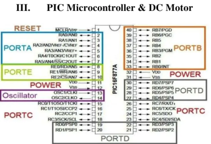
PIC Microcontroller & DC Motor
Figure 2: Pin configuration of PIC 16f877A
w w w . a j e r . o r g
Page 197
DC MOTOR:
Figure 3: DC Motor
INSTRUCTIONS:
Both inputs low -Motor Halt.
First input high & second input low-motor forward. First input Low & second input High-motor reverse.
Both inputs high-Motor Halt.
IV. Lists of AT Command & Register Segment
Register A: UCSRA
RXC TXC UDRE FE DOR PE U2X MPCM
R R/W R R R R R/W R/W
Our Value: UCSRA –OXOO
Register B: UCSRB
RXCIE TXCIE UDRIE RXEN TXEN UCSZ2 RXB8 TXB8
R/W R/W R/W R/W R/W R/W R R/W
Our Value: USCRA - 0X18
Register C: USCRC
URSEL UMSEL UPM1 UPM0 USBS USCZ1 UCSZO UCPOL
R/W R/W R/W R/W R/W R/W R/W R/W
1
0
0 0
0
1
1
0
Our Value: UCSRC – 0x86
URSEL - - - UBRR-11 UBRR-10 UBRR-9 UBRR-8
UBRR-7 UBRR-6 UBRR-5 UBRR4 UBRR-3 UBRR-2 UBRR-1 UBRR-0
w w w . a j e r . o r g
Page 198
IV.
ANDROID APP
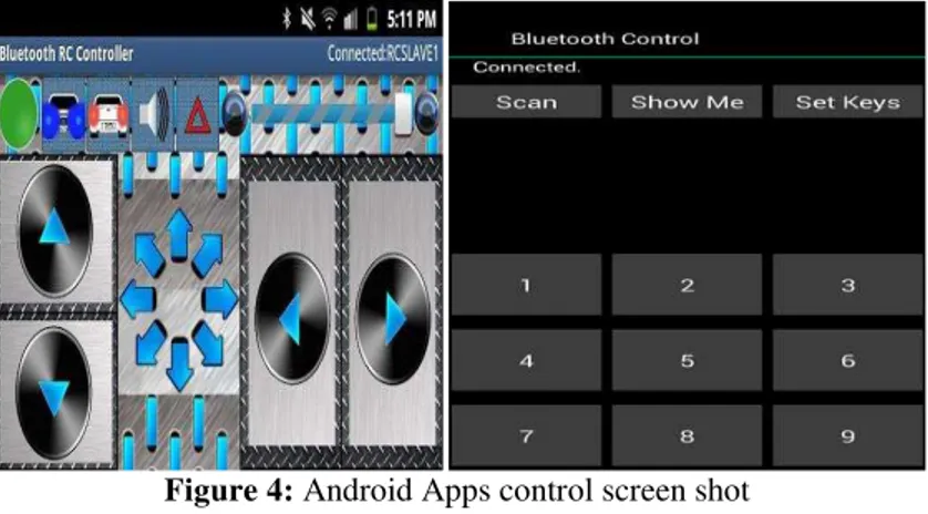
Below is the screenshot of Android application which is used in this project to control the Robot. This application has 9 keys / commands. We have used 7 commands. Command 7 and 9 are not used and are reserved for future scope. User can even rename these key text as Forward / Reverse using the Set Keys option [3]. User needs to turn on the Bluetooth on his/her mobile and press scan button as shown below. Then connect to the Bluetooth receiver on robot [4]. Once the connection is established then the application will show connected status as shown below.
Figure 4: Android Apps control screen shot
V.
PROTEUS SIMULATION & HARDWARE
This project consists of a microcontroller, 16 x 2 alphanumeric LCD, two 5V relays, a lamp, DC motor and Bluetooth module. Here at89c51 microcontroller is used. It is an 8 bit microcontroller and it requires supply voltage of 5V DC [5] [6]. Use 7805 power supply circuit to provide 5V DC to the microcontroller. We can use 9V DC battery or 12V, 1A adapter to provide the supply to the circuit. For the above circuit additionally you need to connect reset circuit and crystal circuit to the controller to work properly.In the above circuit LCD is used to indicate the status of electrical loads and also used to display received data from Bluetooth. Here LCD is interfaced to the PORT1 of the microcontroller in 4 bit mode. Bluetooth module TX and RX pins are connected to the RXD and TXD pins of controller [7]. Vcc pin is connected to the 5V and GND pin is connected to ground. Controller communicates with Bluetooth module using serial communication (UART protocol). Use a baud rate of 9600 to communicate with Bluetooth. If you want to change the Bluetooth name and password then you need to use Bluetooth AT commands.
Figure 5: Proteus Simulation
w w w . a j e r . o r g
Page 199
VI.
APPLICATIONS &FUTURE SCOPES
APPLICATIONS:
• Surveillance Device
• Home automation
• Wheelchairs
• Military Applications
• Hostages Rescue
FUTURE SCOPES:
• In future we plan to implement our project as follows
It will contain following 3 components:
• A Robot Mounted with camera
• A headset, with a full-color display
• A mission control center
VII.
CONCLUSION
We select all equipment’s based on data sheets. It is feasible to implement Bluetooth communication between smartphone and microcontroller. It can be used in various industries for picking various objects where human intervention is not desired. On a large scale, it can be used to develop robots with military applications. It can be used to target enemy without any human being crossing the territory. It provides for more development of applications based on android operating system. Such as, Application based on sensors (accelerometer, gyroscope) etc.The development of apps for Android in Android SDK is easy and free of cost. With tremendous smart phone in markets, it is bound to have many more applications in near future. It is robust, sensitive and fast moving, hence can be applied in rescue operations.
ACKNOWLEDGEMENTS
We are earnestly grateful to our mentor, MihirBarua, Manager-Technical Sales (Siemens Bangladesh Limited) for providing us with his special advice and guidance for this project. Finally, we express our heartiest gratefulness to the Almighty and our parents who have courageous throughout our work of the project.
REFERENCES
[1]. P. D. Minns, Atmega32 for Arduino Microcontroller System. Author House, 2013
[2]. M. Banzi, Getting started with PIC 16f877a. “O’ Reilly Media, Inc.", 2009
[3]. Arduino Apps, "Arduinouno." Last visited on 06/09/2014
[4]. A. M. Gibb, New media art, design, and the Arduino microcontroller: A malleable tool. PhD thesis, Pratt Institute, 2010
[5]. M. Margolis, Proteus cookbook. “O’Reilly Media, Inc.", 2011
[6]. D. Mellis, M. Banzi, D. Cuartielles, and T. Igoe, "Arduino with Proteus: An open electronic prototyping platform, " in Proc. CHI,
vol. 2007, 2007