Pravin Bharane
et al.
Int. Journal of Engineering Research and Applicationswww.ijera.com
ISSN : 2248-9622, Vol. 4, Issue 9( Version 4), September 2014, pp.137-140
www.ijera.com 137 |P a g e
Design, Analysis and Optimization of Anti-Roll Bar
Pravin Bharane*, Kshitijit Tanpure**, Amit Patil***, Ganesh Kerkal****
*,**,***,****(Assistant Professor, Department of Mechanical Engg., Dnyanganga College of Engg. & Research, Pune)
ABSTRACT
Vehicle anti-roll bar is part of an automobile suspension system which limits body roll angle. This U-shaped metal bar connects opposite wheels together through short lever arms and is clamped to the vehicle chassis with rubber bushes. Its function is to reduce body roll while cornering, also while travelling on uneven road which enhances safety and comfort during driving. Design changes of anti-roll bars are quite common at various steps of vehicle production and a design analysis must be performed for each change. So Finite Element Analysis (FEA) can be effectively used in design analysis of anti-roll bars. The finite element analysis is performed by ANSYS. This paper includes pre-processing, analysis, post processing, and analyzing the FEA results by using APDL (Ansys Parametric Design Language). The effects of anti-roll bar design parameters on final anti-roll bar properties are also evaluated by performing sample analyses with the FEA program developed in this project.
Keywords: FEA, Anti Roll Bar, APDL, Design Parameters.
I.
INTRODUCTION
Anti-roll bar, also referred to as stabilizer or sway bar, is a rod or tube, usually made of steel, that connects the right and left suspension members together to resist roll or swaying of the vehicle which occurs during cornering or due to road irregularities. Vehicle anti-roll bar is part of an automobile suspension system. The bar's torsional stiffness (resistance to twist) determines its ability to reduce
body roll, and is named as “Roll Stiffness”. Most
vehicles have front anti-roll bars. Anti-roll bars at both the front and the rear wheels can reduce roll further. Properly chosen (and installed), anti-roll bars will reduce body roll, which in turns leads to better handling and increased driver confidence. A spring rate increase in the front anti-roll bar will produce under steer effect while a spring rate increase in the rear bar will produce over steer effect. Thus, anti-roll bars are also used to improve directional control and stability. One more benefit of anti-roll bar is that, it improves traction by limiting the camber angle change caused by body roll. Anti-roll bars may have irregular shapes to get around chassis components, or may be much simpler depending on the car.
Ride comfort, handling and road holding are the three aspects that a vehicle suspension system has to provide compromise solutions. Ride comfort requires insulating the vehicle and its occupants from vibrations and shocks caused by the road surface. An anti-roll bar improves the handling of a vehicle by increasing stability during cornering. Handling requires providing safety in maneuvers and in ease in steering. For good road holding, the tires must be kept in contact with the road surface in order to
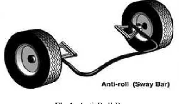
ensure directional control and stability with adequate traction and braking capabilities [1]. The anti-roll bar, as being a suspension component, is used to improve the vehicle performance with respect to these three aspects. The anti-roll bar is a rod or tube that connects the right and left suspension members. It can be used in front suspension, rear suspension or in both suspensions, no matter the suspensions are rigid axle type or independent type. A typical anti-roll bar is shown in Fig 1.
Fig 1: Anti-Roll Bar
II. LITERATURE SURVEY
[1]
Kelvin Hubert Spartan chassis et.al studied and explained anti-roll bars are usually manufactured from SAE Class 550 and Class 700 Steels. The steels included in this class have SAE codes from G5160 to G6150 and G1065 to G1090, respectively. Operating stresses should exceed 700 MPa for the bars produced from these materials. The bars are heated, formed (die forged or upset), quenched and tempered. The high stress regions should be shot peened andPravin Bharane
et al.
Int. Journal of Engineering Research and Applicationswww.ijera.com
ISSN : 2248-9622, Vol. 4, Issue 9( Version 4), September 2014, pp.137-140
www.ijera.com 138 |P a g e
then coated in order to improve the fatigue life of the bar.
[2]Mohammad Durali and Ali Reza Kassaiezadeh
studied & proposed the main goal of using anti-roll bar is to reduce the body roll. Body roll occurs when a vehicle deviates from straight-line motion. The line connecting the roll centers of front and rear suspensions forms the roll axis roll axis of a vehicle. Center of gravity of a vehicle is normally above this roll axis. Thus, while cornering the centrifugal force creates a roll moment about the roll axis, which is equal to the product of centrifugal force with the distance between the roll axis and the center of gravity.
[3] J. E. Shigley, C.R. Mischke explained that the moment causes the inner suspension to extend and the outer suspension to compress, thus the body roll occurs (Fig 2).
Fig 2: A vehicle experiencing body roll during cornering.
Actually, body roll is an unwanted motion. First reason for this is the fact that, too much roll disturbs the driver and gives a feeling of roll-over risk, even in safe cornering. Thus, the driver cannot drive the vehicle with confidence. Second reason is its effect on the camber angle of the tires, which is the angle between the central plane of symmetry of the wheel and the vertical plane at the center of the contact patch. The purpose of camber angle is to align the wheel load with the point of contact of the tire on the road surface. When camber angle is changed due to body roll, this alignment is lost and also the tire contact patch gets smaller. The smaller the contact patch of the tire, the less traction exists against the road surface.
III.
DESIGN OF ANTI-ROLL BAR
The design of an anti-roll bar actually means to obtain the required anti-roll stiffness that improves
the vehicles’ stability and handling performance
without exceeding the mechanic limitations of the bar
material. Since, it’s a straightforward process to
analyze the anti-roll bar, it’s not possible find published studies in the literature. The standard design analyses are performed by manufacturer companies, and the results are not published. Rather, the studies focused on the bushing characteristics and fatigue life analysis of the anti-roll bars is available. Also, some design automation studies about anti-roll bars are present.
Society of Automotive Engineers (SAE), presents general information about torsion bars and their manufacturing processing in “Spring Design
Manual”. Anti-roll bars are dealt as a sub-group of torsion bars. Some useful formulas for calculating the roll stiffness of anti-roll bars and deflection at the end point of the bar under a given loading are provided in the manual. However, the formulations can only be applied to the bars with standard shapes (simple, torsion bar shaped anti-roll bars).The applicable geometry is shown in Fig 3
Fig 3
:
Anti-roll bar geometry used in SAE Spring Design ManualThe loading is applied at point A, inward to or outward from plane of the page. The roll stiffness of such a bar can be calculated as:
L= a+b+c
(L: Half Track Length)
fA =[(P(l13-a3)+ (L/2 *(a+b)2) + (4l22 (b+c))/3EI ]
(fA :- Deflection of point A)
KR = (P*L2) / 2fA
KR : Roll Stiffness of the bar
Max shear stress = T*R/J
T= Torque
Pravin Bharane
et al.
Int. Journal of Engineering Research and Applicationswww.ijera.com
ISSN : 2248-9622, Vol. 4, Issue 9( Version 4), September 2014, pp.137-140
www.ijera.com 139 |P a g e
According to the SAE formulations, roll stiffness can be calculated as:-
fA=
1000[(2503)(903)+550*(1602)+4*(2302)*460]*64
3*206000*π*(21.84
)-(164)
= 25.97 mm
KR = 1000*(11002)/(2*25.97) = 23.296 N.m/rad = 406.59 N.m/deg
(Max shear stress) = T*R/J
= 1000*10.8/ (π*(21.8^4-16^4)/32)
= 169.98 N/sq.mm
IV.
ANALYSIS OF ANTI-ROLL BARS
IN ANSYS
4.1 Procedure for Analysis
1) Modeling using APDL 2) Pre-processing
Element Type: MESH200
Element Shape: 4 Noded - Quad element
Material Properties
a. Modulus of Elasticity =206000 MPa b. Poisson’s ratio = 0.27
c. Density = 7800 N/m^2 d. Yield strength = 1400 MPa e. Factor of Safety = 2
f. Allowable stress = Yield strength/2 = 1400/2 = 700 MPa
g. Material Name: AISI 1065
3) Boundary conditions & Loads
Fig 4: Load Step
a. Displacement constraints at bar ends Ux & Uz are fixed for spherical joint. b. ROTy & ROTz DOF are constraint for
pin joint
c. At bushing position, all Dof’s are constraint
d. Ux Dof is constraint at 2nd bush e. Load is applied in Y direction
4) Post processing a. Deflection
b. Von Mises Stresses c. Rolling Stiffness
4.2 Results obtained from APDL (Ansys Parametric Design Language)
For Anti Roll Bar Dimensions
Outer Diameter: 21.8 mm Inner diameter: 16 mm Bushing Position: 400 mm
Fig 5: Equivalent Von Mises Stress Distribution on the Bar
Fig 6: Deflection of Bar
4.3 Results Obtained for above Dimensions:
1) Deflection: 25.86 mm
2) Von Mises Stresses: 332.307 N/mm2 3) Maximum Principal Stress: 351.393 N/mm2 4) Rolling Stiffness: 408.56 Nm/deg
Pravin Bharane
et al.
Int. Journal of Engineering Research and Applicationswww.ijera.com
ISSN : 2248-9622, Vol. 4, Issue 9( Version 4), September 2014, pp.137-140
www.ijera.com 140 |P a g e
V.
R
ESULTS&
DISCUSSIONBelow table shows optimized results of Anti Roll Bar on the basis of combination of
1) Rolling Stiffness & Von Mises Stresses 2) Deflection & Von Mises Stresses
The main goal of using Anti-roll bar is to reduce the body roll, for that purpose we need to increase roll stiffness of Anti-roll bar and also we need to reduce the weight of the roll bar. For improving Anti-roll bar performance optimization is necessary. Optimization is done by trial and error method through 09 results as follows.
Table 1: Optimized Results for Anti Roll Bar
O.D mm
I.D mm
Bushing Position mm
Deflect -ion mm
Von Mises Stress N/mm2
Rolling Stiffnes s Nm/de g
21.8 16 300 27.814 389.636 379.96
21.8 16 390 25.964 332.270 406.98
20 16 350 45.43 540.162 232.96 20 16.5 350 50.23 607.366 210.80 20 16.5 420 48.58 610.079 217.92 21.8 16 400 25.86 332.307 408.56 20 15 350 38.96 465.494 271.23
21.8 16 420 25.694 344.59 411.26
20 17 390 55.55 761.53 190.72
VI.
C
ONCLUSION Anti-roll bars are tunable vehicle components
which have direct effect on the vehicle’s
performances.
By changing the parameters of the bar, bar properties can be improved.
The time required for analysis of Anti-roll bar using APDL (Ansys Parametric Design Language) is very short and can be repeated simply after changing any of the input parameters which provides an easy way to find an optimum solution for anti-roll bar design.
The most obvious effect of using hollow section is the reduction in mass of the bar.
Locating the bushings closer to the centre of the bar increases the stresses at the bushing locations which results in roll stiffness of the bar decreases and the max Von-mises stresses increases
By Increasing the bushing stiffness of Anti-roll bar , increases Anti- roll stiffness, also increasing the stresses induce in the bar
.
R
EFERENCES[1] Kelvin Hubert Spartan chassis, “Anti-Roll Stability Suspension Technology” SAE PP. 2005-01-3522.
[2] Mohammad Durali and Ali Reza Kassaiezadeh
“Design and Software Base Modeling of
Anti- Roll System” SAE PP – 2002-01-2217.
[3] J. E. Shigley, C.R. Mischke, “Mechanical Engineering Design”, 5th Ed. McGraw-Hill, pp. 282-289, 1989.