Abstract—Overrunning clutches are devices for transmitting rotary motion in one direction only. These mechanisms are widely used in automotive industry, for example, in torque converters, impulse stepless transmissions, inertial continuously variable transmissions, starter engine starting system, and in other similar devices, where torque transmission is performed only in one direction. There are many different designs of the overrunning clutches, for example, ball, roller, cam, ratchet, spring ones, etc. But despite such a variety of designs and great efforts to establish reliable overrunning clutches, these mechanisms are still the weakest parts of many drive systems. Therefore, creation of reliable overrunning clutches is an urgent problem of mechanical engineering. Unfortunately, existing designs of the overrunning clutches have insufficient reliability and durability, which in many cases limits reliability of drive as a whole. The weakest links of the overrunning clutches are the so called wedging elements.
This paper describes a promising new design of overrunning clutches. In this design only a small part of torque is transmitted through the weak wedging elements, and the main part of this torque is transmitted through friction disc surfaces, which allows to unload the wedging elements and substantially improve the reliability and durability of the overrunning clutches in comparison with known designs of overrunning clutches. Investigation of the redistribution of amount of torque transmitted through the wedging elements and the friction disc surfaces was done. It was shown that in suggested design there is the principal possibility of reducing of the amount of the torque transmitted through the wedging elements in tens and hundreds times. Besides, it was developed and investigated a mathematical model describing the dynamics of the overrunning clutches of relay type. Feature of the developed model is that, despite of the variability of the structure, dynamics of the overrunning clutches is described by only one system of differential equations, which greatly simplifies the study of periodic solutions and their stability.
Manuscript received March 10, 2015; revised April 5, 2015. The work was conducted with the financial support of the Ministry of Education and Science of the Russian Federation in the framework of the complex project "Development of scientific and technical solutions for control of power distribution in transmissions of trucks to improve their energy efficiency and fuel economy" according to the contract no. 14.574.21.0106 d.d. 08.09.2014 between the Ministry of Education and Science of the Russian Federation and the applied R&D works performer - Federal State Educational Institution of Higher Professional Education "South Ural State University" (National Research University). Unique identifier for the applied R&D (project) is RFMEFI57414X0106.
S. V. Aliukov is with the South Ural State University, 76 Prospekt Lenina, Chelyabinsk, 454080, Russian Federation (corresponding author, home phone: +7-351-267-97-81; sell phone: 8-922-6350-198; e-mail: [email protected]).
A. V. Keller is with the South Ural State University, 76 Prospekt Lenina, Chelyabinsk, 454080, Russian Federation (e-mail: [email protected]).
A. S. Alyukov is with the South Ural State University, 76 Prospekt Lenina, Chelyabinsk, 454080, Russian Federation (e-mail: [email protected]).
Index Terms—Dynamics, overrunning clutch, relay, solution I. INTRODUCTION
VERRUNNING clutches transmit rotary motion in only one direction [1–3]. They are widely used, for example, in hydraulic transformers, pulsed continuous transmissions, inertial automatic torque transformers, electrical starters for motors, metal- and wood-working drives, and so on.
Unfortunately, existing overrunning clutches are insufficiently reliable and durable and in many cases limit the reliability of the drive as a whole.
Thus, the insufficient life of overrunning clutches delays the use of inertial automatic continuous transmissions, which have many benefits over existing transmissions [4]. In most known overrunning clutches, the whole torque is transmitted through wedging (or, in other words, locking) elements such as balls, rollers, eccentric wheels, pawls, slide blocks, and wedges, whose operation at large loads may limit the life of the mechanism. Therefore, in the present work, we propose an overrunning clutch of relay type, in which only a small part of the torque is transmitted through the locking element [5]; the remainder is transmitted through long-lived elements.
To insert images in Word, position the cursor at the
insertion point and either use Insert | Picture | From File or copy the image to the Windows clipboard and then Edit | Paste Special | Picture (with “float over text” unchecked).
II. PRINCIPLE OF ACTION OF THE OVERRUNNING CLUTCH The overrunning clutch of relay type reduces the load on the weak locking elements by one or two orders of magnitude in comparison with existing designs [6-8]. Its use in inertial transmissions and other machines considerably improves drive performance [9-11]. Therefore, the development of a well-founded design method for such overrunning clutches will permit their broader introduction in industrial drives.
The operation of the overrunning clutch of relay type is analogous to that of an electrical relay, in which a small current flows through a weak electrical circuit and triggers the main electrical circuit, which transmits the main energy flux.
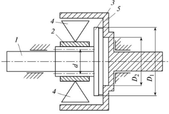
In Fig. 1, we present one design of overrunning clutch of relay type. .
Frictional disk 3 is attached to drive shaft 1, which is positioned in internal ring 2 by means of a screw–nut transmission. Locking elements 4 interact with external ring
On the Question of Mathematical Model of an
Overrunning Clutch
S. Aliukov, A. Keller, and A. Alyukov
5, which is connected to a driven shaft. The drive shaft 1 and driven shaft turn independently if the velocity of the drive shaft is less than that of the driven shaft or if the shafts turn in opposite directions. In that case, the torque in the drive shaft is not transmitted to the driven shaft. When the velocity of the drive shaft is equal to that of the driven shaft, elements 4 lock, and the torque is transmitted from drive shaft 1 through ring 2, elements 4, and ring 5 to the driven shaft. The drag torque on ring 2 results in rotation of the drive shaft relative to the internal ring.
Fig. 1. Overrunning clutch of relay type: D1,D2are external and internal diameters of the frictional surfaces of elements 3 and 5; d is mean diameter
of the helical surface
Since the drive shaft and the internal ring interact through a screw–nut transmission, the rotating drive shaft is shifted axially toward the internal end surface of ring 5 to the point of frictional contact with the surface of disk 3. In other words, the torque is transmitted from the drive shaft to the driven shaft not only through the locking elements but also through those surfaces.
When the velocity of the drive shaft is less than that of the external ring, elements 4 unlock, and no longer transmit the torque. The axial force no longer pushes the drive shaft toward internal ring 2. The surface of frictional disk 3 moves away from the internal end surface of external ring 5, and no torque is transmitted through the frictional surfaces. The overrunning clutch of relay type is completely open.
Despite the frictional contact of disk 3 and ring 5, the overrunning clutch of relay type is free of the main deficiency of frictional clutches: large power losses due to slipping of the frictional disks, accompanied by heating and buckling. The frictional contact of disk 3 and ring 5 in the overrunning clutch of relay type only occurs when their velocities are equal.
III. DISTRIBUTION OF THE TORQUE BETWEEN PARTS OF THE OVERRUNNING CLUTCH OF RELAY TYPE
The axial force on the drive shaft only appears when the overrunning clutch is locked. This benefit of the frictional disk clutch as a means of transmitting large torques at surface contact (and hence with small distributed loads) is fully apparent in overrunning clutches of relay type. In Figure 2, we show the forces in the screw pair of the overrunning clutch.
Torque M1, transmitted through the wedging elements of the overrunning clutch, is determined by the formula
1
M Q r , (1) here rd/ 2
Torque M2, transmitted through friction surface of the units 3 and 5, is found by the following expression
2 2
2 ( 1 1 2 2)
2
3 ( 1 2)
f P R R R R
M
R R
, (2)
here f is coefficient of friction in the frictional contact;
1/ 2, 2/ 2.
1 2
R D R D
Full torque, which is transmitted from the drive shaft to the driven one, is found as the sum M M1M2.
It is not so difficult to obtain the relationship between the scalars of forces P and Q (Fig. 2)
cot
PQ . (3)
Fig. 2. Forces in the screw pair: (1) drive shaft; (2) internal ring of freewheel mechanism; , , are resultant, axial, and azimuthal forces on
the drive shaft from the screw pair; δ is inclination of helical line
We are interested in relationship between the components 1
M and M2 of the full torque M, therefore, using (1), (2), and (3), we can write the ratio
.
2 2
2 ( ) cot
2 1 1 2 2
3 ( )
1 1 2
M f R R R R
M r R R
(4)
Dividing numerator and denominator of the right-hand side of (4) on R R1 2 0 and denoting k R1/R2, after some transformations we find
.
2
2 ( 1) cot
2 1
2
3 ( )
1
M f R k k
M r k k
. (5)
Let k2 k p. Then (5) can be rewritten in the form 2 2 1 cot (1 1).
3 1
M f R
M r p
(6)
It is clearly, that R1 R2, therefore, k 1, and p 2. Taking these relations under consideration, let us do the following estimation 1 1 1 3
2 p
. Then, using the expression (6), we can estimate the ratio of the moments
2 1 M M
2 2
3 1
M
A A
M
, (7)
here.A f R1 cot r
.
As it follows from (7), the distribution of the torque on the components, transmitted by the wedging elements and the friction pair, is determined by the value of A. This value depends linearly on coefficient of friction f and radius of the external circumference R1 of the frictional contact. The dependence of A on the angle of the helix and the average radius r of screw thread is not linear (although it is
monotonically decreasing in the real domain of the arguments) and represents a higher interest for further study.
Fig. 3 shows the dependence of the ratio 2 1 M M
on the
angle of the helix. Curve 1 corresponds to the lower (dashed line) and the upper (solid line) boundaries of the estimation (7) when values of the parameters are
0, 3, 1 0, 2 m, 0, 02 m.
f R r For the curves 2 radius
0,1m. 1
R All other parameters were taken the same as for the curves 1.
Fig. 3. Dependence of the ratio of the components M1 and 2M on the angle helix
From (6) it follows that the ratio of the components of the torque increases without limit as one of the following conditions (or a combination of these conditions) exists:
, 0, 0.
1
R r Consequently, under these conditions it is possible to unload the wedging elements of the overrunning clutch on an arbitrarily large value. We do not consider the case f because the coefficient of friction is limited (usually f [0,1 0, 4] ). Although it is
clear that the more f the more the ratio of the moments (6), which also leads to the discharge of the wedging elements.
The magnitude of the torque, transmitted through the wedging elements of the overrunning clutch, can be smaller than the torque, transmitted through the friction surface, more than a hundred times. Of course, the main part of the initial torque is transmitted from the drive shaft to the driven
one through the friction surface. Wedging elements of the overrunning clutch in this case are almost completely discharged. It can dramatically improve the reliability and durability of the overrunning clutch in general. However, note that even if the torque, transmitted through the friction surface, is more than the torque, transferred through the wedging elements, only in some times (as opposed to tens or hundreds of times), this can lead to a significant increasing of reliability and durability of the overrunning clutch compared to a conventional roller overrunning clutch.
A shortcoming of the design of the overrunning clutch, shown in Fig. 1, is the occurrence of axial force acting on the drive shaft 1 and the internal ring 2. Thus, there is a need to compensate this force, for example, by thrust or radial-thrust bearings. To avoid this shortcoming, we have developed design of overrunning clutch, shown in Fig. 4.
Fig. 4. Scheme of overrunning clutch of relay type with compensation of action of axial forces
On the drive shaft 1 there are two parts in which helical cuts with opposite direction threads are made. On these parts the friction discs 2 and 3 are installed. Internal ring 4 of the overrunning clutch is mounted on bushings discs 2 and 3 by means of splined joint with the possibility of free axial movement. The external ring 5 of the overrunning clutch is also installed by splined joint with the possibility of axial movement in internal part of cylindrical sleeve portion 6 which is connected with the driven shaft.
The principle of operation of the overrunning clutch of relay type is similar with the mechanical screw vise. Availability of screw thread of opposite thread direction allows compensating the axial forces acting on the friction disks 2 and 3.
The proposed scheme of the overrunning clutch is also a relay type design, as it implies the presence of a conventional overrunning clutch with wedging elements. This clutch is necessary for the operation of the friction connection. The most part of torque is transmitted through this connection.
IV. MATHEMATICAL MODEL OF THE OVERRUNNING CLUTCH OF RELAY TYPE
Let us consider the dynamics of the overrunning clutch of relay type.
Given the variability of the structure, the mathematical model of such a mechanism can be described as a set of systems of differential equations written in sections.
motion of the clutch is as follows
••
( 1 2) ,
•• •• , ••
, 3
J J M
J M C
here , , are the angles of rotation of the drive shaft, the internal and external rings of the overrunning clutch of relay type respectively; J1 2 3,J ,J are moments of inertia of the drive shaft, the internal and external rings with moments of inertia of the wedging elements given to these rings respectively; M C is moment of resistance acting on the external ring.
When angular velocities of the drive shaft and the external ring are equal, there is a transition to the second section, whereby the drive shaft performs an axial movement until stopping with the end surface of the external ring. The differential equations of the motion in this case take the form
2 ••
( 1 2) 1;
4 2
•• •• ;
••
( 2 3) ,
mh h
J M F
J J MС
here m is mass of the drive shaft; h is pitch of the thread; 1
F is axial restoring force acting on the drive shaft.
When the end surfaces of the drive shaft and the external ring rest against each other there is the transition of the system to the next section, in which all parts of the overrunning clutch rotate as a single unit. The equations of motion in this section are written as follows
••
( 1 2 3) ;
•• •• •• .
J J J M MС
Solution of the obtained systems of differential equations does not cause any problems. The problem arises in the construction of periodic solutions. In this case it is necessary to track the transition moments from one section to another one, because the overrunning clutches of relay type are technical systems with variable structure. The solution is to bring all the systems of differential equations to a single system. Indeed, the amount of axial clearance between the end faces of the drive shaft and the external ring can be minimized.
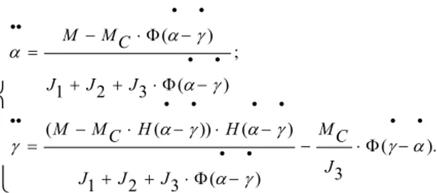
Applying the Heaviside function Ф(x) and its analytical
approximation H x( ) 0, 5 atan( )Nx
, where N is
preassigned sufficiently large number, the equations of motion of the freewheel mechanism can be written as a system of differential equations:
• •
•• ( )
; • •
( )
1 2 3 • • • •
•• ( ( )) ( ) • •
( ). • •
3
( )
1 2 3
M M C
J J J
M MC H H MC
J
J J J
Recording of the equations of motion in the form of (8) allows us to avoid the need to monitor the moments of changing of laws of the motion in the transition from one section to another one. Is sufficient to specify only the initial conditions, which greatly simplifies the study of the dynamics of the overrunning clutch and finding of the periodic solutions.
V. SOLUTIONS OF THE DIFFERENTIAL EQUATIONS OF THE MOVEMENT OF THE OVERRUNNING CLUTCH OF RELAY TYPE
Fig. 5 shows the graphs of the solutions of the system (8), obtained by the Runge-Kutta method with usage of computer program MathCAD. The torque was determined by the dependence M Mд1Mд2sin(t), where
,
1 2
Mд Mд are constant coefficients, is angular frequency. The solid line shows the graph of the angular velocity of the drive shaft, the dot line shows the angular velocity of the external ring depending on time.
Fig. 5. Graphs of the angular velocities of the drive shaft and the external ring versus time
The system parameters were taken as follows:
2 2 2
0, 2 kg m ; 0,1kg m ; 0.8 kg m ;
1 2 3
rad
6 N m; 20 N m; 6 N m; 10 .
1 2
s
J J J
Mд Mд MC
The initial conditions were as follows . •(0) 5rad; (0) 8• rad; (0) (0) 0
s s
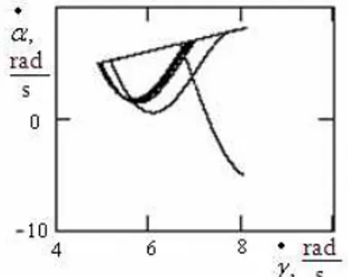
of the design of the overrunning clutch of relay type, the values of the angles of rotation of its units can be taken arbitrarily at any time. Therefore, to determine the limit cycle it is enough to monitor equality of the angular velocities at the beginning and end of the cycle. Taking into account this remark, cyclic trajectory can be seen in the space of angular velocity of the drive shaft and the external ring (Fig. 6). The obtained limit cycle is shown by thick line. As we can see, the yield on the limit cycle is fast enough.
Fig. 6. Graphs of the cyclic trajectories with access on the limit cycle In Appendix it is shown a computer program to find numerical solutions of the differential equations describing dynamics of the overrunning clutch of relay type.
V. CONCLUSION
In this paper it was proved that using the suggested design of the overrunning clutches of relay type it is possible to reduce load on wedging elements in tens or even hundreds times. It allows increasing durability and reliability of the clutches sharply.
Besides, we would like you to notice that in addition to the considered design of the overrunning clutch of relay type, other designs are possible. All these designs contain input and output shafts, internal and external rings, wedging elements. The drive shaft engages with the internal ring by
kinematic connection providing the creation of axial force when the torque is transmitted through the wedging elements. Interaction of the drive shaft with the external ring (or driven shaft) is carried out not only through the wedging elements, but also by frictional connection. The kinematic connection between the driving shaft and the internal ring which provides the creation of the axial force may be made as a helical gear, as a gear transmission with helical teeth, and by some other design ways. To increase the load capacity, the friction connection of the drive shaft and the external ring (or driven shaft) can be performed by package of friction disks.
REFERENCES
[1] A. Leonov, A., "Micro-ratchet Overrunning Clutches," Moscow, Mashinostroenie, 1982, (in Russian).
[2] A/ Kropp, "New Overrunning Clutches and their Applications," Vestnik Mashinostroeniya, vol. 6, 2005, (in Russian).
[3] V. Maltsev, "Overrunning Clutches of Roller Type," Moscow: Mashinostroenie, 1968, ( in Russian).
[4] K/ Liu, H. Zhang, and E. Bamba, "Dynamic Analysis of an Overrunning Clutch for the Pulse-Continuously-Variable-Speed Transmission," SAE Technical Paper 980827, 1998, doi:10.4271/980827.
[5] S/ Aliukov, "Overrunning Clutches of Relay Type," Tyazholoye Mashinostroeniye, vol. 12, 2010, ( in Russian).
[6] S. Aliukov, "Overrunning clutch of relay type," Patent # 57440 Russian Federation, Moscow, 2006, (in Russian).
[7] J. Kremer, and P. Altidis, "Roller One-Way Clutch System Resonance," SAE Technical Paper 981093, 1998, doi:10.4271/981093.
[8] S. Aliukov, "Dynamics of inertial continuously variable transmissions." INFRA-M, Moscow, 2013, (in Russian).
[9] S. Aliukov. and V. Gorshenin, "On the Question of External Characteristic of the Inertial Continuously Variable Transmission," SAE Technical Paper 2014-01-1733, 2014, doi:10.4271/2014-01-1733.
[10] J. Kish, "Advanced Overrunning Clutch Technology," SAE Technical Paper 781039, 1978, doi:10.4271/781039.
[11] R. King, and R. Monahan, "Alternator Pulley with Integral Overrunning Clutch for Reduction of Belt Noise," SAE Technical Paper 1999-01-0643, 1999, doi:10.4271/1999-01-0643.