Metamaterial inspired improved antennas and circuits
Texto
Imagem
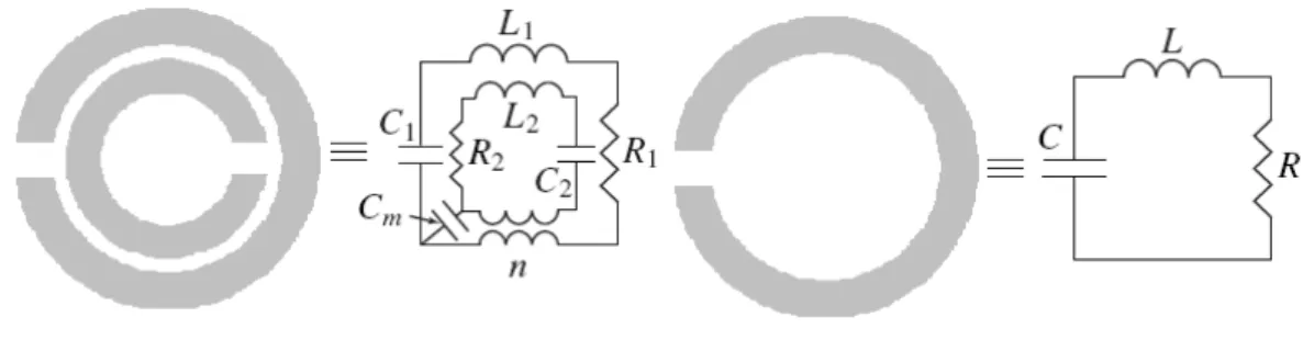

![Fig. 3.8 – Origin of the equivalent circuit elements left and equivalent circuit model for the high-impedance surface right [33]](https://thumb-eu.123doks.com/thumbv2/123dok_br/15554081.96113/44.892.285.609.384.498/origin-equivalent-circuit-elements-equivalent-circuit-impedance-surface.webp)
Documentos relacionados
Theoretical and experimental results of return loss, axial ratio, input impedance and radiation pattern for the antenna located on the aluminum and CFC plates
Here, the width of the ground plane of the proposed fractal monopole antenna is varied and its effect.. on the antenna bandwidth
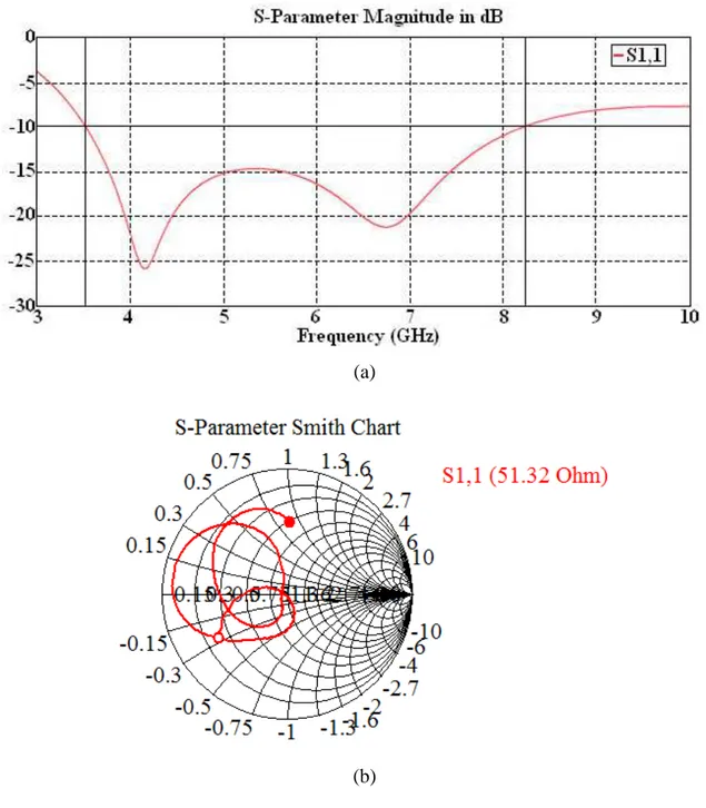
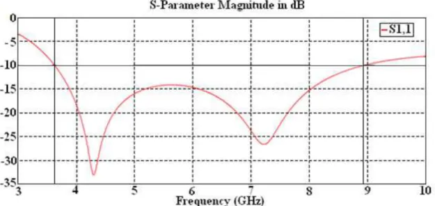
Photograph of the proposed rectangular patch antenna with its corresponding simulated and measured return loss.. The reflection coefficient characteristics of the proposed
Simulated return loss of initial design antenna, with optimum IDC and after size reduction.. As it is shown
An improved measured return loss of 22 dB was later achieved after some tuining adjustments were performed on the filter input and output couplings.. A minimum
Simulated return loss against frequency for the proposed CPW-fed structure-shape substrate wideband antenna, ring shape ground plane and two rectangular slots antenna..
Antenna size miniaturization of 69 % has been achieved by placing double U slots on the ground plane and a line slot DGS (Defective Ground Structure) is used to
The proposed antenna is based on a truncated ground plane and an impedance matching structure formed by a round junction and two chamfers; these modifications
