15th International Specialty Conference - Cold-Fonned Steel Structures 2000
A
theoretical and experimental analysis of cold-formed steel shapes subjected to bending - Channel and simple lipped channelRoberto Martins Gon{:alves1 Maximiliano Maliti Carlos Eduardo Javaronl
EESC - Sao Carlos School of Engineering, USP - University of Sao Paulo Av. Dr. Carlos Botelho, 1465 - CEP 13560-250- Sao Carlos, SP, Brazil
Tel. +55.16.273-9455 - Fax. +55.16.273-9482
ABSTRACT
Cold-formed steel shapes have been widely employed in steel construction, where they frequently offer a lower cost solution than do traditional laminated shapes. A classic application of cold-fonned steel shapes is purlins in the roof panel of industrial buildings, connected to the roof panel by means of screws. The combined effect of these two elements has been the subject of investigations in some countries. Design criteria were included in the AISI Code in 1991 and 1996.
This paper presents and discusses the results obtained from bending tests carried out on shapes commonly used in Brazil, i.e., the channel and the simple lipped channel. Tests were carried out on double shapes with 4.5 and 6.0 meter spans, which were subjected to concentrated loads and braced against each other on the supports and at internlediary points in three different load situations.
The panel shape was also analyzed experimentally, simulating the action of wind by means of a "vacuum box" designed specifically for this purpose.
The test results were then compared to those obtained through the theoretical analysis, enabling us to extract important information upon which to base proposed design criteria for the new Brazilian code.
J Civil Engineer, Doctor's Degree in Structural Engineering, Professor of the Department of Structural
Engineering of the EESC-USP. E-mail: [email protected]
1 Civil Engineer, Doctor's Degree in Structural Engineering, Professor of the Department of Structural Engineering of the EESC-USP. E-mail: [email protected]
3 Civil Engineer, Doctor's Degree in Structural Engineering, Professor of the Civil Engineering Department of UNESP, Bauru campus. E-mail: [email protected]
INTRODUCTION
Cold-formed steel shapes are widely employed as structural elements in the most varied types of steel construction in Brazil. Some examples of their use as framing members are warehousess for a wide variety of uses, residential, commercial or industrial coverings, and low-rise residential buildings. Some examples of isolated structural elements are purlins, longitudinal beams and diagonal bracing elements.
As for the materials used in Brazil, it can be observed that many structures are produced using steel shapes with non-structural quality, the steels having SAE (Society of Automotive Engineers) classification. Although of common quality and easily available in the market, with structural performance proven through experience, these steels carry no guarantee in terms of their physical and mechanical characteristics.
As for the regulating aspects, the Brazilian code on dimensioning of cold-formed shapes, "Calculation of Steel Structures Constituted of Light Shapes", NB143, ABNT (1967) published in 1967, is outdated and in disuse. Along the last thirty years and with the growing use of cold-formed shapes for structural purposes, designers have found it necessary to resort to foreign codes, principally those of the American Iron and Steel Institute, AISI.
Research work in the area of steel structures in Brazil has expanded in recent years, contributing significantly to the growing use of steel in Brazilian civil construction and toward the educational improvement and qualification of the professionals whose activities focus on the design and building of these structures.
To achieve these improvements, the activities in the area of metal structures of the Department of Structural Engineering, Sao Carlos School of Engineering have, in the past few years, focused on incrementing research in steel structures. As a result of this research work, the area of metal structures has been engaged in coordinating the revision and updating of the NB 143, ABNT (1967) code, which should culminate in a new edition of the Brazilian code for the design of cold-formed structural steel structural elements. This work, which is part of a series of research projects on the use and application of steel in Brazilian metal construction, presents the findings of tests carried out on cold-formed steel shapes with cross sections of the channel and simple lipped channel types, as well as the results of the tests of these steel shapes in roof panel systems tested in a "vacuum box" to simulate the effect of wind suction on roof panels. These tests were developed at the Structural Lab of the Structural Engineering Department, Sao Carlos School of Engineering.
MATERIAL
To detennine the characteristics of steel strength, tests were perfonned on 12 (twelve) specimens prepared according to the ASTM A370 specification, detennining the tensile yield point (Fy) and the tensile strength (Fu), for which three specimens each were taken from four different steel sheets.
Table 1 presents the results obtained from these tests. Elongation was measured on the measurement basis of 50rom. All the specimens presented a defined yield level and the value of the modulus of elasticity (E) was 205,000 MPa, a nonnative value for steel. TABLE 1 - Mechanical characteristics of the steel used
Test A Elongation Ny Nu Elongation Fy Fu
(mm2) (rom) (kN) (kN) (%) (Mpa) (Mpa)
IA 38.130 68.42 13.40 17.45 36.84 351.43 457.64
IB 37.324 67.15 13.00 17.00 34.30 348.30 455.47
lC 38.440 66.75 13.10 17.30 33.50 340.79 450.05
2A 28.125 66.56 9.80 13.35 33.12 348.44 474.67
2B 27.630 64.95 9.85 13.00 29.90 356.50 470.50
2C 27.540 64.45 9.85 13.10 28.90 357.66 475.67
3A 28.409 66.85 9.45 13.10 33.70 332.64 461.12
3B 27.725 65.96 9.30 12.85 31.92 335.44 463.48
3C 28.181 65.91 9.55 13.10 31.82 338.88 464.86
4A 39.122 68.43 13.40 17.80 36.86 342.52 454.99
4B 38.626 66.08 42.70 17.40 32.16 328.79 450.47
4C 38.440 65.12 13.00 17.60 30.24 338.19 457.86
Mean value 32.77 343.30 461.40
Standard deviation 2.50 9.23 8.69
NORMATIVE ASPECTS
In its most recent versions, the American Iron and Steel Institute (AISI), a specific code on the design of fonned steel structural members, still detennines the strength of cold-fonned steel beams according to the results of the work of Winter (1943, 1944 and 1959). The theoretical solution of Timoshenko, Gere (1961) for a simply supported "I" beam under equal moment, equation (1), has been employed as a reference.
The effects of the moment gradient and the several support conditions, on the other hand, are adjusted by means of an empirical modification factor applied to the results obtained by Timoshenko, Gere (1961). This approximation has been used for over 50 years.
Approximate formulas for the moment modification factor, (Cb), have been presented by several researchers.
Salvadori (1955, 1956) solved the problem of an "I" type beam under equal moment using the Raleigh-Ritz method, considering several terms in the development in series of the expressions of lateral displacement and rotation. Later, the SSRC ( Structural Stability Research Council) approximated those results using the following expression:
Cb = 1.75 + 1.05r + 0.3r2 ::;; 2.3 (2)
Throughout the past years, several formulations assuming different hypotheses and support conditions have been published and discussed.
According to Pandey, Sherbourne (1989) and Sherbourne, Pandey (1989), the results of these studies have been similar inasmuch as they either failed to include or simply approximated the torsional warping constant for the sake of analytical simplicity. From this standpoint, the work presents a theoretical solution for lateral torsional buckling of "I" beams in the elastic regime, considering the problem as a superimposition of two hypothetical cases, one corresponding to warping equal to zero and the other having torsional stiffuess equal to zero.
Salvadori's expression was used by the AISI up to its 1991 edition, after which its 1996 edition suggests the use of a new expression for Cb, based on the studies of Kirby and Nethercot:
C = _ _ _ _ 1_2_._5_M---"""'ax"'-_ _ _ _ b 2.5M",.x +3MA +4MB +3Mc
where:
M", •. , = absolute value of maximum moment in the unbraced segment.
M A = absolute value of moment at quarter point of un braced segment.
M B = absolute value of moment at centerline of unbraced segment.
Me = absolute value of moment at three-quarter point of un braced segment.
(3)
When cross loads are applied excentrically in relation to the shear center, the equations Mer and Cb differ from those mentioned earlier.
Kavanagh and Ellifritt (1994), based on their results of tests on simple lipped channel shapes, concluded that the AISI equations may overestimate the lateral buckling strength, particularly in cases where there are two or more intermediary lateral braces. According to these authors, the tests demonstrated the occurrence of failure by distortion at the intersection ofthe flange and the stiffener at the locked points.
For isolated shapes, which are subject to lateral buckling with torsion, the flexural strength, according to the AISI (1996), is obtained by means of the following expression:
M S Me
,,=
Cs
f
(4)
where:
Sf = Elastic section modulus of the unreduced section for the extreme compressive
fiber.
Se = Elastic section modulus of the effective section calculated at a stress MJSf in the
extreme compression fiber.
Me = Critical moment calculated according to Equation (5), Equation (6) or Equation (7).
For Me ";? 2.78Me
(5)
For 2.78My>Me > O.56My
M =-M 10 ( 1 - - -10My
J
e 9 y 36M.
(6)
For Me ::; O.56My
(7)
My is the moment causing initial yield at the extreme compression fiber of the full section
and Me is the elastic critical moment computed by Equation (8) for bending about the
symmetry axis (x-axis is the axis of symmetry):
(8)
where:
Cb = Bending coefficient.
ro
= Polar radius of gyration of the cross section about the shear center.Ly, Lt = Unbraced length of compression member for bending about the y-axis and for
twisting.
Ky, Kt = Effective length factors for bending about the y-axis and for twisting.
For flexural members with a flange connected to a panel, lateral buckling no longer occurs in the transversal section as a whole. Flexural strength is less than that of a laterally braced member, although it is higher than that of a laterally unbraced member. In this case, the partial restriction caused by the panel can be represented by a reduction factor obtained by the ratio between the moment that causes the initiation of yield of the extreme compression
fiber (My) and the ultimate moment (Mu) observed in the tests, equation (5), Johnston,
Hancock (1994); LaBoube (1992); LaBoube (1992); Murray, Elhouar (1994).
The values of R, according to the AISI (1996, 1991), are:
R=OAO for simple span C sections; R=0.50 for simple span Z sections; R=0.60 for continuous span C sections; R=0.70 for continuous span Z sections.
TESTS ON FLEXURE MEMBERS
(9)
The flexure tests were carried out on channel and simple lipped channel type shapes with spans, loads and lateral bracing chosen so as to initiate the occurrence of the local buckling and global buckling failure modes in the tested shapes.
The cross sections and their nominal dimensions are shown in Figure 1. The sheet thicknesses used were 2.25 mm and 3.0 mm.
...
N
iyセ@
iセ@
r=t/
=
セ@
TIl'
I
...
N
y
-rU
セi@
C.G. X
r=t
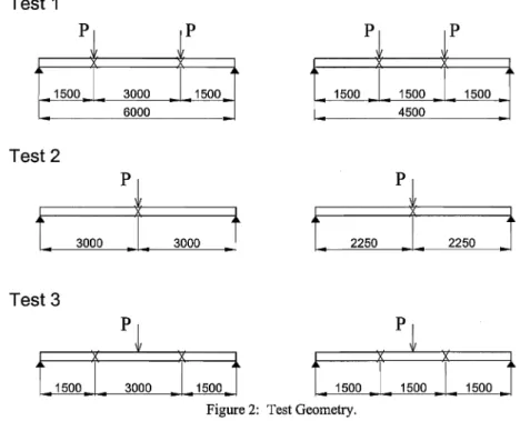
The shapes were subjected to two different spans under three different load situations, as illustrated in Figure 2. The intennediary lateral bracing is indicated in this figure by an x, and this bracing was done between two shapes, which were tested in pairs.
Test 1
p
p
p
p
1500 3000 1500 1500 1500 1500
6000 4500
Test
2
t
30001
3000J
t
22501
2250.t
Test 3
Figure 2: Test Geometry.
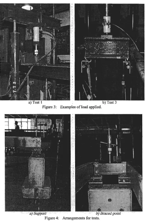
Figure 3 shows the application of loads, the load cell, the hydraulic jack and the displacement transducers positioned for testing.
Figure 4 shows the arrangement used for the supports and the lateral bracing of the shapes. Details ofthat are given in Javaroni(1999).
Figure 3: Examples ofIoad applied.
I 2 3 6 7
] [
- - --5 4
Section A
9 8 SectionB
23 4 7 8
loJ
[
6 5
Section A
10 9
SectionB
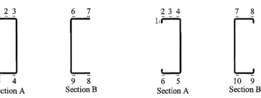
Figure 5: Position of the strain gages at the cross sections.
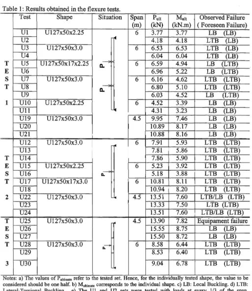
Table 2 shows the results of ultimate load obtained from the tests, the observed failure mode and the failure mode foreseen according to the AISI prescriptions.
It can be observed from this table that the foreseen and actual failure modes differ for some
of the sets tested.
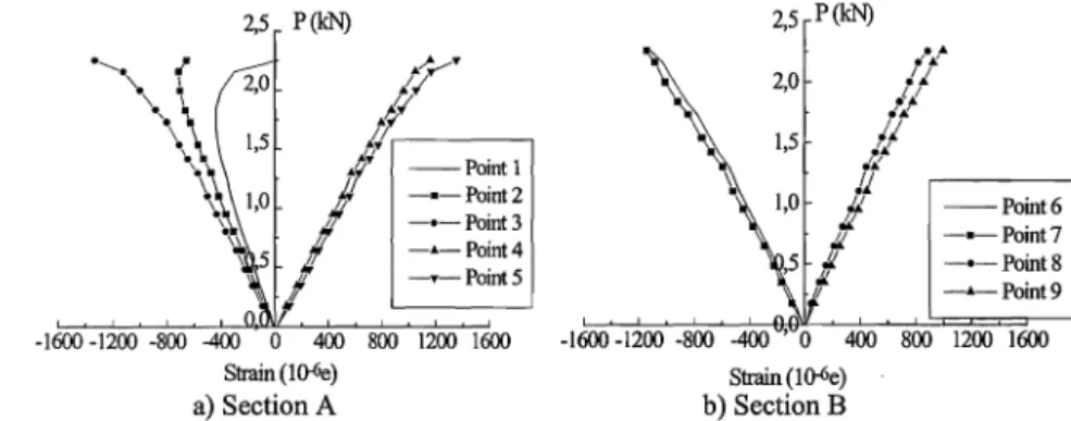
The rotation in the cross section and the horizontal displacements modify the distributions of stresses in the flange, preventing a uniform distribution, as can be observed in the graph of figure 6, which corresponds to the U2 set.
In this test (U2), local buckling occurred in the region approximately 0.5 meter away from
the braced point, leading to an effective torsional buckling length of I meter, which resulted
in Kt==O.5.
In the same way that the rotation altered the distribution of stresses along the flange in the cross section at mid-span, the rotation at the extremities occurred in the opposite direction, in this case increasing the compressive stress on the free edge and justifying the occurrence of local bending of this part where the moment and, consequently, the normal corresponding stresses, are lesser.
Table 3 gives the mean values obtained from the tests and those obtained from the AISII96
Table 1: Results obtained in the flexure tests.
Test Shape Situation Span Pult Mult Observed Failure
(m) (kN) (kN.m) ( Foreseen Failure)
Ul Ul27x50x2.25 6 3.77 3.77 LB (LB)
U2 セ@ 4.18 4.18 LTB (LB)
U3 U127x50x3.0 6 6.53 6.53 LTB (LB)
U4 6.04 6.04 LTB (LB)
T US U127x50x17x2.25 0.-"" 6 6.59 4.94 LB (LTB)
E U6 6.96 5.22 LB (LTB)
S U7 Ul27x50x3.0 6 6.16 4.62 LTB (LTB)
T U8 0."--"'" 6.80 5.10 LTB (LTB)
U9 6.03 4.52 LB (LTB)
1 UlO Ul27x50x2.25 6 4.52 3.39 LB (LB)
Ull セ@ 4.31 3.23 LB (LB)
Ul9 Ul27x50x3.0 4.5 9.95 7.46 LB (LB)
U20 10.89 8.17 LB (LB)
U21 10.88 8.16 LB (LB)
Ul2 Ul27x50x3.0
セ@ 6 7.91 5.93 LTB (LTB)
Ul3 7.81 5.86 LTB (LTB)
T Ul4 7.86 5.90 LTB (LTB)
E Ul5 Ul27x50x2.25 6 5.23 3.92 LTB (LTB)
S Ul6 ッNNセ@ 5.18 3.88 LTB (LTB)
T Ul7 Ul27x50x17x3.0 6 10.81 8.11 LTB (LTB)
Ul8 10.94 8.20 LTB (LTB)
2 U22 U127x50x3.0 セ@ 4.5 13.51 7.60 LTBILB (LTB)
U23 13.33 7.50 LTB (LTB)
U24 13.51 7.60 LTB/LB (LTB)
T U25 Ul27x50x3.0 4.5 13.90 7.82 Equipament failure
E U26 15.55 8.75 LB (LB)
S U27 15.50 8.72 LB (LB)
T U28 Ul27x50x3.0 <L'" 6 8.58 6.44 LTB (LTB)
U29 8.53 6.40 LTB (LTB)
3 U30 9.04 6.78 LTB (LTB)
..
Notes: a) The values of p"w",,,, refer to the tested set. Hence, for the mdlvldually tested shape, the value to be considered should be one half. b) M"IIiIll'" corresponds to the individual shape. c) LB: Local Buckling. d) LTB: Lateral-Torsional Buckling. e) The UI and U2 sets were tested with loads at every 113 of the span.
2,5 P(kN)
... ". セ@ ...
2,0 II
/I
1,5 ,-""" /,/'
1'"
--PointlOセ@
-·-Point2 !1 -·-Point3,;
-4-Point41/ -.-Point5
1/
1/
-1600 -1200 -800 -400
°
400 800 1200 1600sエイ。ゥョHiセI@
a) Section A
2,5 P(kN)
..
,;""2,0 Ii
Ii
1,5 .11 11"If
Ii
"
--Point6"
-·-Point7/L
./L -·-Point8
JI
-4-Point9
1
-1600 -1200 -800 400 800 1200 1600
Strain (1 ()-6e)
b) SectionB
Figure 6: Applied load vs, strain - Set U2.
Table 3: Comparison ofthe results obtained (K,=O 5; Ky=l 0)
Section Span Test
(m) (number)
Ul27x50x3,00 6,0
Ul27x50x3.00 4.5
Ul27x50x2.25 6.0
Ul27x50x17x2.25 6.0
Ul27x50x17x3.00 6.0
Ul27x50x3.00 6.0
Ul27x50x2.25 6.0
Z127x50x17x2.25 6.0
Mean values obtamed for the tested sets. "Loads applied at every 113 of the span.
1 2 3 1 2 3 1 2 1 2 1 1 1 Pull (kN) 6.32 7.86 7,99 10.57 13.45 15,17 4.39 5.20 6.78 10.87 6.28 4.12 5.86
PAISI PultlP AISI
(kN) (kN)
5.73 1.103
7,84 1.003
6.05 1.321
9.44 1.120
11.11 1.211
12.83 1.182
3.60 1.219
5.37 0.968
7.18 0.944
10.28 1.057
5.85 1.073
3.84 1.073
TESTS ON BEAMS HAVING ONE FLANGE CONNECTED TO SHEATING
Figure 7 shows the cross sections of the analyzed shapes.
y y
"'J
.. -=L
-,-/
x ....
セ@ e.G. x
r=t
if= ...
50Figure 7: Cross sections for the purlins.
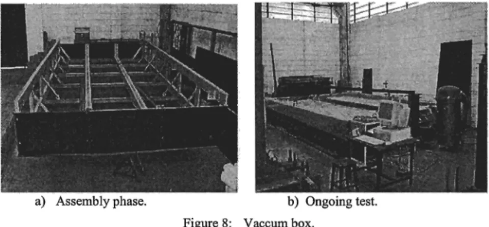
Testing was carried out in a device called a "vacuum box", which consists of a box whose design dimensions may vary from 3m x 6m up to 12m x 6m, in 1m x 6m modules. Its lateral faces and bottom are made of 21mm-thick plywood. The frame is made of cold-formed steel shapes, as illustrated in figure 8.
a) Assembly phase. b) Ongoing test.
Figure 8: Vaccum box.
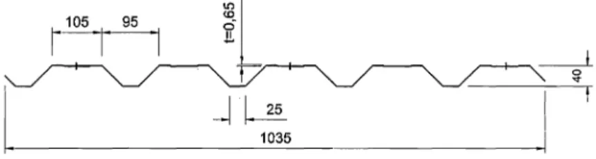
The steel tiles employed had a 4,010 mm-long trapezoidal cross section whose characteristic dimensions are indicated in figure 9.
1105 I 95 I
iL
セ@
17
0...
l
Mセ@ セ@
1035
Figure 9: Cross section of the steel rooftile in the assembly position.
A total of 15 tests were carried out with three different types of cross sections for the shapes. Seven of these tests were carried out without sag rods and 8 with two sag rods, one at every 113 of the span, as indicated in table 4.
Table 4: Tested shapes.
Test Shape Sag rods
1 U127x50x3.00 No
2 U127x50xl7x3.00 No
3 Z127x50x17x3.00 No
4 U127x50x3.00 No
5 Ul27x50x3.00 No
6 U127x50xI7x3.00 No
7 U127x50xI7x3.00 No
8 U127x50x2.25 113 ofthe span
9 U127x50x2.25 113 ofthe span
10 U127x50x2.25 113 of the span
11 U127x50x3.00 113 ofthe span
12 Z127x50x17x2.25 113 of the span
13 Z127x50xl7x2.25 113 of the span
14 Z127x50x3.00 113 of the span
15 Z127x50x3.00 113 ofthe span
screws Figure 10: Sag rods for the purlins.
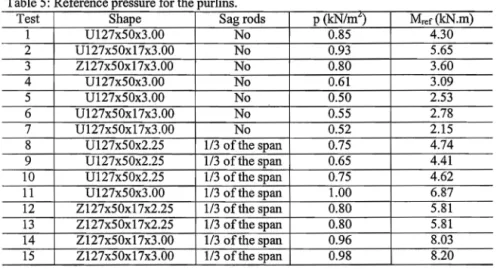
Table 5 gives the results of the pressure applied in the tests. This pressure refers to the relative value of displacement in the mid-span equal to 11100 of the span (56.2 mm). The use of this value is justified as being that for which the damage of the structure is had, hence characterizing its failure. The value of the moment in the mid-span section, M"" corresponds to the value of the pressure for 11100 of the span. This moment is one of uniformly distributed load along the length of the shape, whose value is obtained by the product between the value of the reference pressure and the influence width for the shape. This influence width was determined based on the vertical displacements measured at half span for the lateral shapes and for the instrumented shape.
Table 5: Reference pressure for the purlins.
Test Shape Sag rods p (kN/m<) M.·ef(kN.m)
1 Ul27x50x3 .00 No 0.85 4.30
2 Ul27x50x17x3.00 No 0.93 5.65
3 Z127x50x17x3.00 No 0.80 3.60
4 Ul27x50x3.00 No 0.61 3.09
5 Ul27x50x3 .00 No 0.50 2.53
6 Ul27x50x17x3.00 No 0.55 2.78
7 Ul27x50x17x3.00 No 0.52 2.15
8 Ul27x50x2.25 113 of the span 0.75 4.74
9 Ul27x50x2.25 1/3 of the span 0.65 4.41
10 Ul27x50x2.25 113 ofthe span 0.75 4.62
11 Ul27x50x3.00 113 of the span 1.00 6.87
12 Z127x50xI7x2.25 113 of the span 0.80 5.81
13 Z127x50x17x2.25 113 ofthe span 0.80 5.81
14 Z127x50x17x3.00 1/3 ofthe span 0.96 8.03
The types of failure that occurred for the shapes connected to the roof tiles were excessive displacement and local buckling of the flange, possibly associated to distortion. In the case of the shapes without sag rods, already evident for the low pressure values, induced early failures in the element. This is important and should be analyzed as a possible failure mode for the purlins for which sag rods are not used. Figure 11 illustrates this phenomenon.
Figure 12 presents the strains corresponding to the U127x50x17x3.0 type shape, test 7, measured at the cross section in mid-span. In this test, in addition to the strains in the flanges, figure 12a, measurements were also taken along the web of the shape, the results of which are given in figure 12b.
']
765
\
\,,1.
-Point 1 -·-Point2 -·-Point3 -'-Point4 -.-Point5 -.-Point6 -·-Point7
J
I 8\ I"
\ 110
'111 112
p(kNIm2)
\
セッ@ セ@
|
oセ@tt
• r'
• r
t
0,6 T !,r ! 0,4
1
2
i
--Point8 -·-Poin\9 -·-Point10 -'-Point 11 -.-Point 12
600 900 1200 -1200 -900 -600 -300 0 300 600 900 1200
An observation of the strains that occurred in the cross section at mid-span lead to some important considerations. This graph shows the decrease in strains, in absolute values, for points 2, 3 and, less pronouncedly, for point 5.
This decrease is due to the high rotation of the cross section close to the joint of the web with the tractioned flange, leading to the appearance of tension near the stiffeners and compressive stresses in the region ofthe web and causing the variation in the distribution of stresses in the cross section of the shape. This finding is in agreement with the hypotheses adopted by the Pekoz, Soroushian (1982) model, in which the stresses in the cross section are computed assuming the superimposition of two different stages: the first due to vertical displacement and the second one due to horizontal displacement and cross sectional rotation.
This evidence was found for all the shapes without sag rods, although it was more strongly marked for the channel type shapes.
The behavior of the shapes braced by sag rods is quite different from that in which these elements are not used. As observed earlier, for the shapes without sag rods, the horizontal displacements begin concomitantly to loading while, in the presence of sag rods, these displacements remain practically absent nearly up to the ultimate load.
Figure 13 shows the behavior of pressure versus strain for a U127x50x3.0 type shape,
which corresponds to test 11, and is representative ofthe behavior of the shapes tested with
sag rods.
1,0 0,8 0,6
p(kNlm2)
I
,
,:
,.---,
I
--Point 1I -.-Point2
I'
-o-Point3 -A.-Point4 -T--Point5 --+--Point 615001200-900 -600 -300' 0 300 600 900 1200 1500
strain 1 Q-6e
Figure 13 - Pressure vs. strain - Test 11; with sag rods.
]
664
Figure 14 presents illutrative photographs of the rupture that occurred in the system in two different situations. The first photograph, figure 14a, shows the failure for a pilot test while figure 14b illustrates the failure that occurred in test 11.
Figure 12: Examples of failures observed for the purlins.
The FR value, Table 6, expresses the ratio between the flexural strength in test and the
moment of initial yielding based on the elastic section modulus of the effective section.
Table 6 - Ultimate and yield moments.
Test
I
ShapeI
p (kN/m2)I
M"r (kN.m)I
My (kN.m)Without sag rods
1 U127x50x3.00 0.85 4.30 7.52 0.57
2 U127x50x17x3.00 0.93 6.54 9.28 0.70
3 Z127x50x17x3.00 0.80 3.60 10.16 0.35
4 U127x50x3.00 0.61 3.09 7.42 0.42
5 U127x50x3.00 0.50 2.53 7.42 0.34
6 U127x50xI7x3.00 0.55 3.86 9.28 0.42
7 U127x50xI7x3.00 0.52 3.65 9.28 0.39
With sag rods
8 U127x50x2.25 0.75 4.74 5.21 0.91
9 U127x50x2.25 0.65 4.41 5.21 0.85
10 U127x50x2.25 0.75 4.62 5.21 0.89
11 U127x50x3.00 1.00 6.87 7.42 0.92
12 Z127x50x17x2.25 0.80 5.81 7.46 0.78
13 Z127x50xI7x2.25 0.80 5.81 7.46 0.78
14 Z127x50x17x3.00 0.96 8.03 9.77 0.82
15 Z127x50x17x3.00 0.98 8.20 9.77 0.84
-"' .
Note. p(kN/cm) mdlcates the value of the apphed pressure correspondmg to the displacement equal to 11100 of the span (56.2 mm). For this pressure value, the value of the M"rmoment was determined.
The average values of the results obtained were: Channel type without sag rods:
Simple lipped channel type without sag rods: Channel type with 2 sag rods:
Z section with 2 sag rods:
It should be pointed out that these values should be restricted to the conditions used in the tests described herein and that their extrapolation to other situations is subject to possible errors in assessment ofthe flexural strength.
Only one test was carried out for the Z section without sag rods; therefore, the value obtained (F R=0.35) cannot be considered representative of this tipe of shape. These values were compared to the results of 25 other tests performed by LaBoube (1992, 1991) and Pekoz, Soroushian (1982) together with those developed by Javaroni (1999). One can conclude, therefore, that the values presented herein practically reproduce the mean values and standard deviations obtained by LaBoube.
In addition, the value of FR=OAO for channel type shapes proved to be appropriate for shapes both with stiffened and with unstiffened flanges.
In an earlier evaluation (Javaroni, 1999), the Pekoz, Soroushian (1982) method presented results of normal stresses that were coherent with the strains measured in the cross sections of the tested shapes. However, the values of the spring stiffness coefficient (10 varied considerably and the determination of a theoretical value for design purposes requires a deeper study owing to the various parameters involved. It should also be pointed out that specific testing procedures exist to determine this coefficient. An advantage of the Eurocode (1993) procedure is that it provides an analytical expression to determine the spring stiffuess coefficient.
CONCLUSIONS
This study analyzed cold-formed steel shapes whose cross sections, specifically the channel type, are widely employed in steel construction in Brazil.
For the isolated shapes, the results calculated by means of the AISI (1996) procedure proved satisfactory, provided buckling coefficient values are used that are appropriate for the details ofthe lateral bracing employed.
It was observed that unforeseen limit states occurred in some of the tests, which may be associated to the closer proximity of the laterally braced points, where the stress gradient in the compressed flange resulting from the rotation of the cross section may inhibit local buckling of the flange. On the other hand, this same gradient may superimpose the compressive stresses, leading to possibly unforeseen local buckling ofthe flange.
The experimental analysis of the shapes connected to the steel roof tiles was carried out in two stages: purlins without sag rods and purlins 2 two sag rods.
Tests carried out on the purlins showed differing behaviors for the shapes with and without the use of sag rods.
tested cross sections. This fact, characterizing the ultimate limit state of purlins without sag rods, is considered of crucial importance and should be seen as a failure mode for future study, for which a mathematical model suitable to the behavior of the shape must be found. The use of the reduction factor proved to be a fairly simple procedure for use in routine design, however, it is subject to the conditions used in tests and its extrapolation may lead to gross errors.
When sag rods are used, the shapes present practically no horizontal displacement of the compressed flange, showing only vertical displacements. This finding suggests that purlins should be analyzed as bars subject to simple flexure. The sag rods also allowed for a gain in purlin strength, which was represented by the increased ultimate pressure in the "vaccum box".
ACKNOWLEDGMENTS
The authors gratefully acknowledge the Brazilian research funding institution F APESP for its financial support of this research project, and USIMINAS S.A. for the donation of the steel used to conform the shapes for testing.
REFERENCES
AMERICAN IRON AND STEEL INSTITUTE (1996) Cold formed steel design manual. AISI, Washington.
ANIERICAN IRON AND STEEL INSTITUTE (1991) LRFD Cold formed steel design manual. AlSI, Washington.
ASSOCIA<;AO BRASILEIRA DE NORMAS TECNlCAS. (1967) Calculation of Steel Structures Constituted of Light Shapes; NB-143. ABNT, Rio de Janeiro. 31 p. JAV ARONI, C. E. (1999) Cold-formed steel members in flexure:
theoretical-experimental analyses. Sao Carlos, 1999. 255p. Thesis. Sao Carlos School of Engineering, University of Sao Paulo.
JONHSTON, N.; HANCOCK, G. (1994) Calibration of the AISI R-factor desigu approach for purlins using Australian test data. Engineering Structures, v.16, n.5, p.342-347.
KAVANAGH, K. T.; ELLIFRITT, D. S. (1994) Design strengths of cold-formed channels in bending and torsion. Journal of Structural Engineering, ASCE, v.120, n.5, p.1599-1607, May.
LaBOUBE, R. A. (1992) Estimating uplift capacity of light steel roof system. Journal of Structural Engineering, ASCE, v.118, n.3, p.848-852, Mar.
LaBOUBE, R. A. (1991) Uplift capacity of Z-purlins. Journal of Structural Engineering, ASCE, v.117, n.4, p.1159-1166, April.
PANDEY, M. D. SHERBOUNE, A. N.; (1989) Unified v. integrated approaches in lateral-torsional buckling of beams. The Structural Engineer, v.67, p.245-249, July. PEKOZ, T.; SOROUSHIAN, D. (1982) Behavior of C and Z purlins under uplift. Sixth
SALVADOR!, M. G. (1955) Lateral buckling of I beams. Transactions, ASCE, v.120, p.1165-1177.
SALVADOR!, M. G. (1956) Lateral buckling of eccentrically loaded I columns.
Transactions, ASCE, v.121, p.1163-1178.
SHERBOUNE, A. N.; PANDEY, M. D. (1989) Elastic, lateral-torsional stability of
beams: moment modification factor. Journal of Constructional Steel Research, v.13,
p.337-356.
TIMOSHENKO, S. P.; GERE, J. M. (1961) Theory of elastic stability. 2.ed. New York:
McGraw-Hill. 541p.
WINTER, G. (1959) Cold-formed, light-gage steel construction. Journal of the
Structural Engineering, ASCE, v.85, n.ST9, p.151-173, Nov.
WINTER, G. (1944) Strength of slender beams. Transactions, ASCE, v.109,
p.1321-1349.
WINTER, G. (1943) Lateral stability of unsymmetrical I-beams and trusses in
bending. Transactions, ASCE, v.108, p.247-260.
APPENDIX - NOTATION
A Cb
C
w E Fy Fu GIx> Iy It
K
t Ky L Lt Ly Mmax,MA , MB ,
Me Me Me My Pult P R ro t
Full unreduced cross-sectional area ofthe member Bending coefficient dependent on moment gradient Torsional warping constant of the cross-section Modulus of elasticity of steel, 205 000 Mpa Tensile yield point
Tensile strength Shear modulus of steel
Moment of inertia offull section about principal axis St. Venant torsion constant
Effective length factor for torsion
Effective length factor for buckling about y-axis Full span for simple beams
Unbraced length of compression member for torsion
Unbraced length of compression member for bending about y-axis
Absolute value of moments in an unbraced segment, used for detennining Cb
Critical moment Elastic critical moment Moment causing a yield strain Load test
Pressure in "vacuum box" Reduction factor