National Highway Alignment from Namakkal to Erode Using
GIS
T. Subramani
1, S.Krishnan
2,
C. Kathirvel
3, S. K. Bharathi Devi
41Professor & Dean, Department of Civil Engineering, VMKV Engg. College, Vinayaka Missions University,
Salem, India.
2
Associate Professor and Head, Department of Mechanical Engineering, Mahendra College of Engineering, Salem,India.
3, 4Associate Professors, Department of Civil Engineering, VMKV Engg. College, Vinayaka Missions
University, Salem, India.
ABSTRACT
The vision of the Highway Alignment is to increase the capacity, connectivity, efficiency and safety of the Highways System so as to enable balanced socioeconomic development of all sections of the people and all regions from NAMAKKAL to ERODE via and to reduce the traffic and travelling of the state. It is to establish shortest path for road network time in the roads which provide a better and comfortable base for updating the traffic and other related information in road administration. It is to identify the short route for the vehicles traveling from NAMAKKAL to ERODE and to reduce the time travel for the vehicles with possible paths or routes or places for laying eco-friendly highway. To optimize the route for the vehicles traveling from NAMAKKAL to ERODE using GIS with Network analysis tools. From this we can find the suitable route for peoples to carry out without any traffic disturbances and protecting the environment. It also took advantages of GIS capabilities that offer the ability to overlay maps, merge them, and perform spatial analysis on various layers of information in either two or three dimensions
KEYWORDS: National Highway, Alignment, Namakkal, Erode, GIS
I.
INTRODUTION
Determining the best route through an area is one of the oldest spatial problems. This problem has been recently solved effectively using GIS and Remote sensing technologies. During the last decade, a few attempts have been made to automate the route planning process using GIS technology. Constructing a new road or aligning an old one can be very expensive, with cost depending on the alignment selected. Costs are increased by long structures, by large volume of cut and fill, and by unbalanced cut and fill were discrepancy has to be dumped or borrowed.
There are numerous environmental issues that need to be addressed to and show that they alignment does not reduce biodiversity or degrade the environment. The first step in producing high quality alignment depends on obtaining suitable data on geology, land use, slope, soil and drainage. In addition, there are issues such as land value and ownership, social and economic impact, and identifying environmentally sensitive areas.
1.1 GENERAL
Remote sensing can be defined as the collection of data about an object from a distance. Human and many other types of animals accomplish this task with the aid of eyes or by the sense of smell or
hearing. Geographers use the technique of remote sensing to monitor or measure of phenomena found in the earth’s lithosphere, biosphere, hydrosphere and atmosphere. Remote of the environment by the geographers is usually done with the help of mechanical devices known as remote sensors. These gadgets have a greatly improved ability to receive and record information about an object without any physical contact. Most sensing devices record information about an object by measuring an objects transmission of electromagnetic energy from reflecting and radiating surfaces
“Remote sensing is the science of making inference about from measurement, made at a distance, without coming into physical contact with
the object under study”, that is remote sensing refers
to any method, which can be used to gather information about an object without actually coming in contact with it.
1.2 CONCEPT OF SIGNATURES
“Electromagnetic radiation when incident on a
surface, gets reflected, absorbed, reemitted or transmitted through the material depending upon the nature of the object and the wavelength of the incidence radiation.
1.3 MULTI SPECTRAL CONCEPTS
Spectral vibration is the most often used signature, especially in the optical –IR region. The spectral vibration of some of the natural objects in the 0.4 to 2 micron range. However it is not easy to generate continuous spectral for identification objects. Therefore a practical solution is to make observance in a number of discrete spectral regions, usually referred as spectral bands.
1.4 REMOTE SENSING SYSTEMS
With the background treatise on remote sensing we have made so far, it would now be easier to make an analysis of the different stages in remote sensing. Origin of electromagnetic energy.
Transmission of energy.
Intervening of energy or self emission. Detection of energy.
Transmission or coding of the sensor output. Collection of ground truth.
Data analysis and interpretation. Integration of interpretation images.
We shall now briefly describe the various components of a remote sensing system.
1.5 REMOTE SENSORS
The instrument used to measure the electro magnectic radiation reflected or emitted by the target under study is usually referred to as remote sensors. Sensors which sense natural radiation either emitted or reflected form the earth is called passive sensors, which are carry Electromagnetic radiation of a specific wavelength or band of Wavelength to
illuminates the earth’s surface are called active
sensors. The major parameters of a sensing system which can considered as Indicators of the quality of data and which have bearing on optimum utilization for specific end users include spatial resolution, spectral resolution, radiometric resolution and temporal resolution, these are four resolution are the most basis requirement of any sensor system
1.6 PLATFORMS
Sensor system needs to be placed on suitable observation platforms and lifted to a pre-defined altitude. Platforms can be stationary or mobile depending upon the needs of the observation mission and the constraints. Some of platforms are considered such as, geostationary, which are about 36000km above earth. Second is sun-synchronous satellite, this type of satellites are nearer to earth like few km above.
1.7 DATA PRODUCT
Acquired data has number of errors due to Imaging characteristics of the sensors
Stability and orbit characteristic of the platforms
Scene/surface characteristic Motion of the earth
Atmospheric effect
Data product are generated after correcting these errors so that the inherent quality of the original information of the scene. The data product is generated in standardization formats either in photographic or digital form to allow further analysis.
1.8 DATA ANALYSIS
Visual interpretation and digital image processing are two important techniques of data analysis needed to extent resources related information either independently or in combination with other data.
1.9 VISUAL INTERPRETATION
Visual interpretation has been the traditional method for extracting information from a photograph based on the characteristic such as tone, texture, shadow, shape, size, association etc. though the number of color tones recognized by human brain is large, it is still limited. When photographic products are generated from digital data, the contrast is further degraded. Visual interpretation poses serious limitation when we want to combine data from various sources. Above all, when a large volume of data has to be analyzed, it cannot meet the throughout requirement.
1.10DIGITAL PROCESSING TECHNIQUES
Digital techniques facilities quantitative analysis, make use of full spectral information and avoid individual basis. Simultaneously analysis of multi temporal and multi sensor facilated in digital methods. In digital classification, the computer analysis the signature, so as to associates each pixel with particular features space in some fashion so that each pixel in the feature pixel in the feature space can be uniquely associated with one of the classes.
1.11UTILITY OF GIS TECHNOLOGY
The information generated from remote sensing can be represented in many ways. it could be generated as tabular data ,such as, area under different crops in each district or a map GIS is essentially a computer based system designed for capturing and storing both spatial and tabular data and combination them to which one can apply spatial
analysis tools as per the analyst’s requirement/model.
1.12ROADWAYS
bullock carts, etc. some are private vehicles while others are meant to move either a large number of public or goods over long distances.
1.13TRAFFIC ENGINEERING
This area of transportation engineering deals with the analysis, design and operation of facilities used by vehicles of various transportation modes. Such a study assumes at most importance in the case of roadways as the number of vehicles using transportation facilities as the highest as well as the most varied both in terms of their type origins and destination their purposes etc. generally the scope of traffic engineering in the most commonly of the term is limited to roadway traffic.
1.14 AIM AND SCOPE OF THE
INVESTIGATION
To establish shortest path for road network from Namakkal to Erode.
To provided a better and comfortable base for updating the traffic and Other related information in road administration.
To identify the short route for the vehicles traveling from Namakkal to Erode and to reduce the time travel for the vehicles.
Our main scope is to reduce the traffic and travelling time in the roads.
To prepare various thematic maps for analyzing the environmental status.
To find possible paths/routes/places for laying eco-friendly highway.
II.
GIS FOR ROAD NET WORK
ANALYSIS
2.1 STUDY AREA - ABOUT NAMAKKAL
Namakkal District is an administrative district in the state of Tamil Nadu, India. The district was bifurcated from Salem District with Namakkal town as Head Quarters on 25-07-1996 and started to function independently from 01-01-1997. The district has 4 Taluks (sub divisions); Tiruchengode, Namakkal, Rasipuram, Velur and Kolli Hills(in descending order of population) and has two Revenue Divisions; Namakkal and Tiruchengode. It was ranked second in a comprehensive Economic Environment index ranking of districts in Tamil Nadu not including Chennai prepared by Institute for Financial Management and Research in August 2009. It was major source of Tamil Nadu Economy.It lies in Coordinates: 11°13 8.4 N78°10 1.2 E.
2.2 ERODE
Erode District (previously known as Periyar District) is a district in the western part (Kongu
Nadu) of the state of Tamil Nadu, India. The headquarters of the district is Erode and it is divided into two revenue divisions namely Erode and
Gobichettipalayam. Periyar district was a part of Coimbatore District before its bifurcation on September 17, 1979 and was renamed as Erode District in 1996. Mathematician Srinivasa Ramanujan and social reformer Periyar were from here.It lies in Coordinates: 11°21 N77°44 E.
Existing method
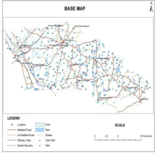
Now peoples are travelling from Namakkal to Erode via Manikampalayam, Tiruchengode and SBP colony approximately 55kms.It take more time and huge traffic in the Tiruchengode area. Hence decide to propose the new highway alignment which is shortest path in the time travelling and avoid traffic.(Fig.2.1)
Fig 2.1 Study Area Map
2.3 DATA COLLECTION
Survey of India Toposheet No. (58 I/2, 58 I/3, 58 I/4,58I/6,58I/8) on the scale of 1:50,000.
Land Sat (Mss) Data 2007
Maps, field work and remote sensing techniques are necessary for proposed road design and construction. Topographic maps, Geomorphology, Land use /Land cover, Drainage, DEM road, Slope and Contour maps were used for this proposed route. The favorable path analysis, using various data and GIS analysis was intended to confirm the best transport route within this site.
2.4 DATA PROCESS AND ANALYSIS
In this implementation, the best route is found for a new road. The steps to find possible path are outlined below. Path is identified by using Arc GIS9. Spatial Analysis Module.
Create source, Destination and Datasets.
Generate different Thematic Maps.(Classify and Weightage)
Create Direction Datasets.
Identified shortest path with Distance and Direction Datasets.
III.
DESIGN GUIDELINES
3.1 PLANNING OF ROAD IN PLAIN AREAS.
Planning of roads in plain area is somewhat different from hill areas. In hill areas alignment of roads has to be circuitous and is primarily governed by the topography. In the plain area we should find the elevation and depression by the surveying. The elevation areas should be leveled by removing the upper surface of the earth and this soil can be used for the filling up the low lying areas.
The roads in our country in plain areas, they have been classified as National Highways Major District and Road, and Other District Roads and Village Roads according to specification, traffic needs and socio economic, administrative or strategic consideration. Some National Highways are point to point which will connect the state boundaries. State Highway will connect all the National Highways. Other District Roads and Village Roads will connect the Major District Roads however from topographical considerations; these can be broadly being divided into Arterial Roads and link roads, Arterial roads will include National/State highway and Major District roads. Link roads take off from Arterial roads to link village/production areas in small/sub-valleys. These will comprise Other District roads and Village roads.
3.2 WIDTH OF ROAD LAND, ROADWAY, CARRIAGEWAY AND SHOULDERS
Table.3.1 gives the Width of Road Land, Roadway, Carriageway and Shoulders
Table 5.1 Width of Road Land, Roadway, Carriageway and Shoulders
3.3 HIGHWAY ALIGNMENT
“The position (or) the layout of the centerline of the highway on the ground is called the alignment”.
Two types:
1) Horizontal alignment 2) Vertical alignment
3.3.1 Requirements
The basic requirements of ideal alignment between two terminal stations are that it should be
a) Short b) Easy c) Safe d) Economical
3.3.2 Factors Controlling Alignment
The various factors, which control the highway alignment, may be listed as:
a) Obligatory points b) Traffic
c) Geometric design d) Economy
e) Other considerations
a) Obligatory points
The various factors, which control the highway alignment of the canal. These control points may be divided in to two categories,
I. Points through which the alignment is to pass II. Points through which the alignment should not
pass.
Obligatory points through which the road alignment has to pass may cause the alignment to often deviate from the shortest (or) easiest path.
Obligatory points through which the road should not pass also may make it necessary to deviate from the proposed shortest alignment.
The obligatory points, which should be avoided while aligning a road, include religious places, very costly structures.
However if there is no alternative and the alignment has to be taken across such an area, the construction and maintenance costs are likely to be very high.
b) Traffic: -
The alignment should suit traffic requirements origin and destination study should be carried out in the area and the desire lines be drawn showing the trend of traffic flow.
c) Geometric design: -
Geometric design factors such as gradient, radius of curve and sight distance also would govern the final alignment of the highway.
Sl. No
Highway Classification
Carria geway Width( M)
Shou lder Widt h(M)
Road way Widt h(M)
1 National Highway And State Highway 1.Single Lane 2.Double Lane
3.75 7.00
2.25 2.90
6,25 8.80
2 Major District Roads And Other District Roads
3.75 2.50 4.75
The absolute minimum sight distance, which should invariably be available in every section of the road is the safe stopping distance for the fast moving vehicles.
d) Economy: -
The alignment finalized based on the above factors should also be economical.
The initial coast of construction can be decreased if high embankments and deep cuttings are avoided and the alignment is choosing in a manner to balance the cutting and filling.
e) Other considerations: -
Various other factors, which may govern the alignment are drainage considerations, hydrological factors, political considerations and monotony.
The vertical alignment is often guided by drainage considerations.
In a flat terrain it is possible to have a very long stretch of road, absolutely straight without horizontal curves.
3.3.3 Special Considerations: - Stability: -
While aligning hill roads, special care should be taken to align the road along the side as the hill, which is stable. The cutting and filling of earth to construct roads on hillside causes steepening of existing slopes and affect its stability.
Drainage: -
Numerous hillside drains should be provided for adequate drainage facility across the road. But the cross drainage structures being costly attempts should be made to align the road.
3.3.4 Engineering Surveys For Highway Alignment
Four stages of the engineering surveys are, a) Map study.
b) Reconnaissance. c) Preliminary surveys.
d) Final location and detailed surveys.
3.4 HORIZONTAL ALIGNMENT
The horizontal alignment should be fluent and blend well with the surrounding topography. The horizontal alignment should be coordinate carefully with the longitudinal profile. Breaks in horizontal alignments at cross drainage structure and sharp curves at the end of long tangents/straight section should be avoided.
Short curves give appearance of kinds, particularly for small deflections angles, and should be avoided. The curves should be sufficiently long
and have suitable transitions to provide pleasing appearances. Curve length should be at least 150 m for a deflection angle of 5 degree and this should be increased by 30 m for each degree deflection angle. For deflection angle less than one degree, no curve is required to be designed.
Reverse curves may be needed in difficult terrain by very sparingly used. It should be ensured that there is sufficient length between the two curves for introduction of requisite transition curves. Curves in the same direction separated by short tangents, known as broken back curves, should be avoided as possible in the interest of aesthetics and safety and replaced by a single curve.
Compound curves may be used in difficult topography but only when it is impossible to fit in a single circular curve. To ensure safe and smooth transition from on curve to the other, the radius of the flatter curve should not be disproportional to the radius of the sharper curve. A ratio of 1:5:1 should be considered the limiting value. Horizontal curves should consist of circular portion of the curve followed by the spiral transitions on both sides. Design speed, super elevations and coefficient of friction affect the design of curves.
Length of transition curve is determined on the basis of change of centrifugal acceleration or the change of super elevation
3.4.1 MINIMUM CURVE RADII.
On a horizontal curve, the centrifugal force is balanced by the combined effect of super elevation and side friction. Basic equation for this condition equilibrium is as follows:
v2/g R = e + f
R = V2/127 (e + f) Where,
R=radius of circular curve in m/sec
v=speed of vehicle in m/sec V=speed of vehicle in km/sec
e =super elevation in meter f = coefficient of side friction between tyre and pavements.
( Taken as 0.15)
g= Acceleration due to gravity in m2/s2
The ratio of the centrifugal force to the weight of the vehicle/w is known as centrifugal ratio. It is equal to v2/gr.
3.5 VERTICAL ALIGNMENT
cross drainage structures should follow the same profile as the flanking road section, with no break in the grade line.
3.6 CO-ORDINATION OF HORIZONTAL AND VERTICAL ALIGNMENT.
The overall appearance of a highway can be enhanced by judicious combination of the horizontal and vertical alignment. Plan and profile of the road should not be designed interpedently but in unison so as to produce an appropriate three dimensional effect. Proper Co-ordination in this aspect will ensure safety, improve utility of the highway and contribute to overall aesthetics. Vertical curvature super imposed upon horizontal curvature gives a pleasing effect. As such the vertical and horizontal curves should coincide as possible and their length should be more or less equal. It is difficult for any reason; the horizontal curve should be somewhat longer than the vertical curve.
IV.
METHODOLOGY
The base (study area) map, Drainage, Slope and Contour maps were prepared with help of SOI Toposheet (on 1:50000 scale). High resolution LANSAT satellite data of 2009 was used and by using Digital Image Processing techniques the following thematic maps such as geomorphology, Land se/Land Cover were generated.
The base (study area) map, Drainage, Slope and Contour maps were prepared with help of SOI Toposheet (on 1:50000 scale). High resolution LANSAT satellite data of 2009 was used and by using Digital Image Processing techniques the following thematic maps such as geomorphology, Land se/Land Cover were generated.
The Digital Elevation Model (DEM) was generated using various GIS based analysis, such as overlay, raster network analysis.
The DEM is used in order to understand the terrain condition, environment factors and social economic status in this study area. Finally possible/feasible route was identified based on various physical and cultural parameters and their inherent properties.(Fig.4.1)
The cost reduction analysis was done for substantiating the formation of ring track
Methodology:
Fig 4.1 Data Interpretation
V.
TOPOGRAPHY
Topographic and geologic data of the proposed rail network area were prepared in a GIS ready format and used as input to the GIS database. The locations of roads, railways, wetland, forests
and drainage features were derived from the topographic map layer.
The map that produced by SOI is the base for national topographic database and has a number of features for instance location of roads, railways, wetland, forests, drainage features, elevation points. In this proposed project, digital elevation model (DEM) was prepared from the elevation data.
Toposheet 58 I/2, Toposheet 58 I/3, Toposheet 58 I/4,Toposheet 58 I/4, Toposheet 58 I/6, Toposheet 58 I/8 were used in this study
It was used as input to the least cost and shortest pathway analysis.
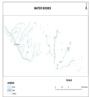
5.1 GEOMORPHOLOGY
Different landforms present in the area are depicted in this geomorphic unit were extracted from the satellite image by digital data interpretation and incorporated into the GIS database.
Fig.5.2 Road details
These geomorphic units were classified into Plateau, Scarp face, Debris slope, Bazada, Residual hill and pediments (deep, Shallow & moderate.Fig.5.1 shows Water bodies.Fig.5.2 shows Road details. Fig.5.3 shows Well location
Fig.5.3 Well location
5.2 TRAFFIC CENSUS
Table 5.1,5.2,5.3,5.4,5.5 & 5.6 shows the traffic census details at different location in different road network
Table 5.1 Traffic Census -Tiruchengode To Velur Point-Police Station (Time: 8:00 A.M To 10:00
A.M.)
Table 5.2 Traffic Census - Erode To Tiruchengode
Point- Old Bus Stand Road Time: 8:00 A.M To 10:00 A.M.
Table 5.3 Traffic Census Namakkal To Tiruchengode
Point-Namakkal Bus Stand Time: 8:00 A.M To 10:00 A.M.
S.NO TYPE OF
VEHICLES
NO.OF VEHICLES
1 Two wheelers 2860 2 Light Motor Vehicles 275
3 Bicycles 43
4 Autos 76
5 Buses 296
6 Truck/Lorries 134
7 Minivan 93
8 Animal driven
Vehicles 4
9 Others 5
S.NO TYPE OF
VEHICLES
NO.OF VEHICLES
1 Two wheelers 2871 2 Light Motor Vehicles 322
3 Bicycles 43
4 Autos 84
5 Buses 205
6 Truck/Lorries 217
7 Minivan 88
8 Animal driven Vehicles
5
9 Others 3
S.N O
TYPE OF VEHICLES
NO.OF VEHICLES
1 Two wheelers 3054 2 Light Motor Vehicles 304
3 Bicycles 27
4 Autos 49
5 Buses 174
6 Truck/Lorries 316
7 Minivan 103
8 Animal driven
Vehicles 6
Table 5.4 Traffic Census - Erode To Tiruchengode
Point-Pallipalayam Bus Stop Time: 4:30 P.M To 6.30 P.M.
Table 5.5 Traffic Census - Chithalandur To Tiruchengode Point- Chithalandur Time: 4:30
P.M To 6:30 P.M.
Table 5.6 Traffic Census - Tiruchengode To Namakkal Point- Malai Adivaram Time: 4:30 P.M To 6:30 P.M.
5.3 WHY GIS USED
Manually aligning a railway is a tedious job because
Mapping and modelling could not be done easily.
Visualising the study area is not possible (only way is to have field visit)
Volume of data to be handled is large. Time consuming.
Manual analysis of data requires much computation and greater possibility for committing mistakes.
Suggested path might not be appropriate. A new railway should be aligned very carefully as improper alignment would result in the following disadvantages,
1. Increase in construction cost 2. Increase in maintenance cost 3. Increase in operational cost
Once a highway is constructed, it is not easy to change the alignment due to increase in cost of adjoining land and construction costly accessories along the constructed path. Hence the importance of careful consideration to be over emphasized can be realized.
5.4 GEOGRAPHICAL INFORMATION
SYSTEM
Visualization is a form of communication, which is universal and which has the ability to form an abstraction of the real world into graphical representation. Once a project is developed, it is necessary to communicate the effect of proposed changes to other agencies and public review groups to facilitate decision making. Some of the changes in the environment can be modeled and visualized using GIS.
VI.
OVERVIEW OF SOFTWARE
6.1 INTRODUCTION TO ARC GIS Arc GIS 9.2 is a product of ESRI. It adds topology for the geo database. You can choose which feature classes in a feature dataset participate in a spatial relationship with other feature classes in a feature dataset or within themselves.
Certain rules can be applied, such as polygons cannot overlap one another, lines cannot have dangling nodes, and points must be completely inside the bounds of a polygon. The number of spatial integrity rules offered for the geo database far exceeds those used in the Arc Info Workstation coverage model, and are much more flexible.
The editing abilities of Arc Map have been improved to leverage these spatial integrity rules and to help find and fix topological errors more easily and quickly. Arc Map is the premier application for desktop GIS and mapping.
6.1.1 Visualize:
In no time you will be working with your data
geographically; seeing patterns you wouldn’t see
S.NO TYPE OF
VEHICLES
NO.OF VEHICLES
1 Two wheelers 3160 2 Light Motor Vehicles 271
3 Bicycles 38
4 Autos 86
5 Buses 277
6 Truck/Lorries 312
7 Minivan 107
8 Animal driven Vehicles
8
9 Others 5
S.NO TYPE OF
VEHICLES
NO.OF VEHICLES
1 Two wheelers 792 2 Light Motor Vehicles 97
3 Bicycles 34
4 Autos 24
5 Buses 73
6 Truck/Lorries 106
7 Minivan 56
8 Animal driven Vehicles
10
9 Others 4
S.N O
TYPE OF VEHICLES
NO.OF VEHICLES
1 Two wheelers 1647 2 Light Motor Vehicles 214
3 Bicycles 32
4 Autos 174
5 Buses 312
6 Truck/Lorries 83
7 Minivan 74
8 Animal driven Vehicles
5
before, hidden trends and distributions, and gaining new insights.
6.1.2 Create:
It’s easy to create maps to convey message. Arc
map provides all the tools you need to put your data on a map and display it in a effective manner.
6.1.3 Solve:
Working geographically lets you answer
questions such as “where is...? “How Much...? And
What if ....?” Understanding these relationships will
help you make better decisions.
6.1.4 Present:
Showing the results of your work is easy. You can make great-looking publication –quality maps and create interactive displace that links reports, graphs, tables, drawings, photographs and other
elements to your data. You’ll that communicating
geographically is a powerful way to inform and motivating others.
6.1.5 Develope:
The Arc map customization lets you tailor the interface to suit your needs or the needs of your organization build to automate your work and develop stand alone applications based on aroma mapping components. See about customizing Arc map and Arc catalogue for more information.
6.1.6 Modeling:
Statistical methods allow life phenomenon to be represented in a mathematical or statistical way. The advantage of modeling real life phenomena include: The determination of factors or variables which
most influence the behavior of the phenomena include :
The ability to predict or forecast the long term behavior of the phenomena.
Once a statistical model has been developed, simulations of the real life phenomena can be performed. The modeler can construct a wide range of scenarios by changing the influential factors. The key advantage of conducting simulations is that phenomenon’s predicted behavior can be observed without placing the phenomena.
6.2 VECTOR MODEL:
The vector data model, the spatial locations of features is defined on the basis of coordinate pairs. These can be discrete, taking the forms of points linked together to form discrete sections of line; linked together to form closed boundaries encompassing an area attribute data pertaining the individual spatial features is maintained in an external base.
In dealing with vector data any important concept is that topology. Topology derived from geometrical mathematics is concerned with order, contiguity and relative position rather than with actual linear dimensions. Topology is useful in GIS because many spatial modeling operations do not require coordinate locations, only topological information For example to find an optimal path between two points requires a list of the arcs or lines that connect to each other and the cost to transverse them in each direction. It is also to possible to perform the spatial modeling and interrogation process without using stored topology, by processing the geometrical data directly by generating topology on the fly or using vector object model as and when it is required.
6.3 RASTER MODEL:
The spatial representation of an object and its related non spatial attribute are merged into a unified data file. In practice the area under study is covered by a fine mesh or matrix of grid cells and particular ground surface attribute value of interest occurring at the centre of each cell point is recorded as the value for that cell. It should be noted that while some raster models support the assignment of values to multiple attribute per discrete cell, other strictly to a single attribute per cell structure.
Within this model spatial data is not continuous but is divided into discrete units. In terms of regarding where individual cells are located in space, each is referenced according to its row and column position within the overall grid. To fix the relative spatial data according to its row and column position within the overall grid. To fix the relative spatial position of the overall grid (i.e.) to geo reference it, the four corners are assigned planer coordinates. An important concept concerns the size of the component grid cell and referred to as grid resolution.
The following information should always be recorded when assembling, compiling and utilizing raster data.
Grid size ( no of rows and columns) Grid resolution
Geo referencing information (e.g.) corner coordinates, source projection.
Data collection.
Topographic maps are collected to generate multi- layered; geo referenced digital maps on a GIS platform, with the basic inputs of available information. These comprehensive maps shall cover the following aspects:
Slope map
Land use and land cover pattern
Population and settlement pattern
This done using SOI topo sheet (58 I/2, 58 I/3, 58 I/4, 58 I/6, 58 I/8)in the scale of 1: 50000. The boundary is traced over a tracing sheet. Traced boundary is converted to digital format using digitization in Arc GIS9.2
6.4 RASTER CALCULATOR:
Build expressions in the raster calculation by using map algebra to weight raster and combine them as part of a suitability model, to make selections on your data in the form of queries, to apply mathematical operators and functions, or to type Spatial Analyst functions.
Multiline expressions can be typed into the raster calculator. It is useful to build multiline expressions for complex functions, such as cost path or to chain processes together.
For example:
[Cost] = ([land use] + [slope])
[Dist] = cost distance ([source], [cost], back link) Path = cost path ([destination], [dist], back link)
The output dataset shows how suitable they each location is for highway alignment, according to the criteria set in the suitable model. A higher value indicates the locations that are suitable.
6.5 PERFORMING SHORTEST PATH:
It is almost ready to find the shortest path from the source. We have already performed cost weighted distance, creating a distance dataset and a direction dataset using the source point. However it is necessary to decide on the Erode to Namakkal which is the calculation of shortest path to the highway.
The shortest path is calculated using the function
“shortest path” in the Spatial Analyst. Specifying the
destination point as input along with the distance and direction theme, calculates the optimal path which highway has to run. It represent the least cost meaning avoiding steep slopes and land use types considered to be least costly for constructing the Highway from source to destination.
VII.
DISCUSSION
In general the results of the project can be discussed under two aspects,
1. Geotechnical aspects 2. Ecological aspects
Geotechnical aspects:
Case 1:The alignment of highway was done based
on the following criteria:
In this case, both the layers have an equal influence on the alignment of the highway. This is done using the formula,
(reclass_ slope)*0.4 + (reclass land use)*0.6
Table 6.1 Slope Weightage
SLOPE(degrees) Rank
0-5 1
5-10 2
10-15 3
15-20 4
20-25 5
25-30 6
30-40 7
40-50 8
50-70 9
Table 6.2 Land Use Weightage
LANDUSE TYPE
RANK LANDUSE TYPE
RANK
Barren land 2 Sheet rocky
3
Settlement 4 Waste land 1
Non agri-use 7 Cultivable land
5
VIII.
CONCLUSION
The purpose of this study was to develop a tool to locate a suitable less route between two points. The GIS approach using ground parameters and spatial analysis provided to achieve this goal. Raster based map analysis provided a wealth of capabilities for incorporating terrain information surrounding linear infrastructure. Costs resulting from terrain, geomorphology, land use, drainage and elevation resulting the shortest routes for the study area. The existing road path was 115km long from Erode to Namakkal. Results indicate that the route which was designed applying GIS method is more environmentally effective and cheaper.
This proposed shortest route provides traffic free, pollution free, risk free, operating for movement of vehicle passing from Erode to Namakkal. Time and consumption of fuel will also be reduced considerably.
REFERENCES
[1]. Subramani,T. and Elangovan, R “Planning Of A Ring Road Formation For Salem Corporation Using GIS”, International
Journal of Engineering Research And Industrial Applications, Vol.5, No.II, pp 109-120, 2012.
[2]. Subramani,T, Krishnan.S. And Kumaresan.P.K., Study on Exixting Traffic
condition in Salem City and Identify the transport facility improvement projects,
International Journal of Applied Engineering Research IJAER, Vol.7,No.7, Pp 717 – 726, 2012
[3]. Subramani, T, and Malaisamy.P, “Design of Ring Road For Erode District Using GIS”,
International Journal of Modern Engineering Research,Vol.2, No.4, pp 1914 - 1919,2012.
[4]. Subramani, T “Assessment Of Potential Impacts On NH7 – 4 Laning From Salem To Karur”, International Journal of Modern
Engineering Research, Vol.2, No.3,pp 707-715, 2012.
[5]. Subramani, T. “Traffic Study On Road Network And Programming For Fixing Priority To The Identified Transport Improvement Projects In Salem City, Tamilnadu, India”, International Journal of
Scientific and Engineering Research, Vol.3, No.5, pp 1-12, 2012.
[6]. Subramani, T. "Traffic Study On Road Links
and Estimate the Fund required for Identified Road Improvement Projects in Major Urban Centre", International Journal
of Engineering and Advanced Technology, Vol.1, No. 4, pp 76-81, 2012.
[7]. Subramani,T, and Nandakumar,S, “National
Highway Alignment Using Gis”
International Journal of Engineering Research and Applications, Vol.2, Issue.4, pp 427-436, 2012.
[8]. Kadiyali.L.R., ”Traffic Engineering and Transport Planning”, 7th edition, Khanna
publishers, Delhi, 2007.
[9]. Kadyali L.R. and Lal N.B., “Principles and Practices of Highway Engineering”, 5th
edition, Khanna Publishers, New Delhi, 2007.
[10]. Khanna S.K. and Justo C.E.G., “Highway
Engineering”, 9th edition, Nem Chand and
Bros. publishers, Roorkee(U.P) Lindsay R. Peat (1982), “Practical Guide to DBMS
selection”, Walter de Grawyter, New York, 2010.
[11]. Subramani T., “Programming for Implementing Transport Facilities in Urban
Centres”, Urban Engineering Thesis,
Madras – 600025, 1992.
[12]. Subramani T., “Traffic Study On Road Network, To Implement Transport Facility Projects And To Identify The Shortest Travelling Path Using GIS For Salem ”,