Flow Development through a Duct and a Diffuser Using CFD
Prasanta K.Sinha
1, A.K.Biswas
2, A.N. Mullick
2and B.Majumdar
31
Durgapur Institute of Advanced Technology& Management, West Bengal, India
2
Department of Mechanical Engineering, National Institute Technology, West Bengal, India
3
Department of Mechanical Engineering, Jadavpur University, Kolk ata, West Bengal, India
ABSTRACT
In the present paper an extensive study of rectangular cross-sectioned C-duct and C-diffuser is made by the help of 2-D mean velocity contours. Study of flow characteristics through constant area duct is a fundamental research area of basic flu id mechanics since the concepts of potential flo w and frictional losses in conduit flow were established. C-ducts are used in aircraft intakes, co mbustors, internal cooling systems of gas turbines, ventilation ducts, wind tunnels etc., while d iffuser is mechanical device usually made in the form of a gradual conical e xpander intended to raise the static pressure of the fluid flowing through it. Flow through curved ducts is more co mp le x co mpared to straight duct due to the curvature of the duct axis and centrifugal forces are induced on the flowing flu id resulting in the development of secondary motion (normal to the prima ry flow d irect ion) which is manifested in the form o f a pair of contra-rotating vortices. For a diffuser in addition to the secondary flow, the diverging flo w passage, which causes an adverse stream wise pressure gradient, can lead to flow separation. The combined effect may result n non uniformity of total pressure and total pressure loss at the exit . A comparat ive study of different turbulent models available in the Fluent
using
y
as guidance in selecting the appropriate grid configuration and turbulence models are done.Standard k-ε model and RSM models are used to solve the closure problem for both the constant area duct and the diffuser. It has been observed that the Standard k-e model predicts the flow through the constant area
duct and the diffuser within a reasonable domain of the
y
range.Keywords:
C-duct, C-d iffuser, Secondary Motion, Wally
Strategy, k-ε model, Fluent solverNome nclature
Dn Dean Number L Centerline length Rc M ean Radius of curvature
Re Reynold’s number (UavD/)
Uav Inlet Average Velocity
W Inlet Width
b Height of duct
Angle of turn of the curvature Kinematic Viscosity
I.
INTRODUCTION
Diffuser is a mechanica l device usually made in the form of a gradual conica l e xpander intended to raise the static pressure of the fluid flowing through it. Specific use of a diffuser with a proper area ratio should also ensure an adequate amount of uniform flow at the outlet together with a considerable static pressure. Diffusers play an important role in many engineering and industrial applications to accomplish the objectives under geometric constraints. In aircraft gas turbines, high velocity air fro m the wing or fuselage first flows through a diffusing intake where it is decelerated for increasing the pressure, and then fed to the engine compressor. In the design of ventilation and
air conditioning systems, diffusers are commonly used for discharging the conditioned air into the space to be cooled in order to reduce the air velocity and increase the static pressure. In these applications, on one hand there is restriction on space as well as design compatibility to match with the shortest possible duct length, while on the other hand, given cross-sectional shapes at inlet and outlet of the duct has to be satisfied; this compelled to the use of curved diffusers. C-ducts are used in aircraft intakes, combustors, internal cooling system of gas turbines, ventilation ducts, wind tunnels etc. Heat e xchangers in the form of curved ducts are used wide ly in food processing, refrigeration and hydrocarbon industries. Gas turbine engine components such as turbine compressors, nozzle etc. utilise several comp le x duct configuration. Performance of duct flow depends upon the geometrica l and dynamical para meters of the duct. So it is very much essential to design the duct with proper geometry to imp rove the performance.
Study of flow characteristics through constant area ducts is a fundamental research area of basic fluid mechanics since the concepts of potential flow and frictional losses in conduit flow we re established. Duct is a part and parcel of any flu
mechanica l system. It is a passageway made of sheet metal or other suitable materia l used for conveying air or other gases or liquids at different pressures. Depending on its application the shape the duct may be either of straight, curved, annular, polar, sector, trapezoidal, rhomb ic etc. Flo w through curved ducts has practical importance in chemical and mechanical industries in particular. Obviously, compared to a straight duct, flow in a curved duct is more co mp le x due to curvature of the duct axis. It induces centrifugal forces on the flowing flu id resulting in the development of a secondary motion (norma l to primary direction of flow) wh ich is manifested in the form of a pair of counter-rotating vortices. Depending on the objective, fluid mechanical systems often demands for the design of ducts with comple x geo metry (like inlets, nozzles, diffusers, contractions, elbows etc) albeit with high efficiency. In these applications, design of the ducts is based on the mathematica l formulat ion of the flow fie ld fo r the prescribed condition.
Flo w deve lop ment in the cu rved d iffusers is a co mplicate p rocess in fluenced by d iffe rent geo met rica l pa ra met ers like 2θ, Δβ, A R , A S, centre line shape etc . as we ll as the dynamica l para mete rs like in let Mach nu mb er, in let turbulence etc . In any int erna l flo w, flu id nea r the flo w a xis moves at h ighe r ve loc ity than the flu id near the walls due to the in fluence o f bounda ry laye r. I n a cu rved d iffuse r, due to the presence of centreline curvature, flu id near the flow a xis is acted upon by a larger centrifugal force than fluid near the walls. This centrifugal p ressure difference (transverse pressure gradient) forces the faster moving fluid to move outwards pushing the fluid in the boundary layer at the outer wall around the sides towards the inner wall; thus a significant secondary flow (normal to the primary flo w direction) is produced. In addition, the diverging flow passage, which causes an adverse stream wise pressure gradient, can lead to flow separation. The combined effect may result in non-uniformity of total pressure and total pressure loss at diffuser e xit.
Probably, Fo x & Kline, 1962, carried out the first systematic studies on 2-D curved diffusers. They analyzed the performance of the diffusers by varying the ratio between the centreline length to inlet dia meter and also varying the angle of turn. They concluded that a stall occurred at an angle equal to or greater than 50°. Shimizu et al., 1986 e xperimentally studied the performance and internal flow through twisted S-shaped (coiled), U S-shaped, and snake S-shaped bend diffusers having circular cross-section and different area ratios (1.3 to 15.9), d ivergent angles (3°, 6°), and curvature ratios (3, 6), which they have
as a result of h igh surfac e roughness (- 0.5mm) o f the diffusers. Th e pressure re covery coeffic ients of these c ircu la r test diffusers were co mpa rat ive ly lo we r than that of an S- shaped rectangu la r d iffuser of ne arly the sa me area rat io , even with a large r tu rn ing ang le (90°/ 90°,). Th e total p ressure loss coeffic ient fo r a ll the d iffusers we re nea rly the sa me and see med to be independ ent of the ang le of tu rn. The flo w distribut ion was found to be more un ifo rm at the e xit fo r diffuse rs with h ighe r ang le o f turn . El-Askary and Nasr, 2009 studied tu rbu lent flo w through a co mb ined bend -diffuser syste m, consisting of a 90° bend fo llo wed by a d iffuser o f rectangu la r c ross-section and d iffe rent angles (2θ ) rang ing fro m 6°-30° at diffe rent in flo w Reyno lds nu mbe rs. Expe rimenta l and simu lated results showed that , depend ing upon the in let Reyno lds nu mbe r there is an opt imu m d iffuser ang le, which produces min imu m pressure loss and hence good performan ce of such co mp le x geo met ry. Th e asy mmetry o f flo w in the d iffuser due to the installat ion o f a bend at the upstrea m g enerates a side load to th e diffuser wall, wh ich inc re ases with inc reas ing d iffuser ang le and Reyno lds nu mbe r.
Ro we, 1970, ca rried out e xpe riments on circu la r 90° and 180° turn cu rved du cts with Re=0.4xl05 and repo rted the gen erat ion of contra rotat ing vort ices with in the b ends. Bansod & Bradsha w, 1972, studied the flo w cha racte ristics with in the 22.5°/ 22.5° S shaped constant are a ducts of diffe rent lengths and rad ii o f curvatu re . They repo rted th e deve lop ment of a pa ir o f cont ra -rotat ing vort ices in the lo w p ressure zone at the e xit o f the duct wh ich was the consequence of the effect o f strea m wise vort ices deve loped in the first ha lf o f the duct . Enayet et al., 1982, investig ated the turbu lent flo w cha racte ristics through 90° c ircu la r curv ed duct of cu rvatu re rat io 2.8. It was observed that the th ic kness of the in let bounda ry laye r has a significant role on generat ion of seconda ry mot ion with in the duct . Azzola et al., 1986, h ave studied the tu rbu lent flo w cha racte ristics through 180° c ircu lar b end with cu rvatu re rat io of 3.375 th rough e xpe riments as we ll as co mputat iona l methods. They observed a pa ir of cont ra-rotat ing vo rt ices arising out of seconda ry mot ion in both e xpe rimenta l and nu meric al studies. Lacov ides et al., 1987, repo rted the flo w p red ict ion with in 90° curved duct using nu me rica l simu lat ions based on the e xp erimenta l invest igat ion by Taylo r et a l., 1982. They adopted finit e volu me app roach tu solve the se mi-e llipt ica l fo rm o f equat ion fo r 3-D flo w ana lysis consid ering the wa ll funct ion in the reg ion c lose to the wa ll. The resu lt shows a good agree ment b et ween the e xpe rime nta l and nu me rica l an alys is. Th anga m and Hur, 1990,
studied the secondary flo w o f an inco mp ressible viscous flnid in a curv ed re ctangu la r duct by using a finit e volu me method . Th ey repo rted that with the inc rease of De an Nu mb er the seconda ry flo w structure evo lves into a doub le vo rte x pa ir fo r lo w aspect rat io ducts. Th ey co rrelated frict ion facto r as a funct ion of the De an Nu mbe r and aspect ratio . Kim and Pate l, 1994, hav e investig ated on a 90° curv ed duct o f rectangu la r cross-section with aspect ratio 6 us ing five -hole probe and c ross-wire hot wire ane mo mete r. Th ey repo rted the fo rmat ion of vort ices on inn er wa ll due to the pressure driven secondary mot ion origin ated in the co rne r reg ion o f curved duct . Investigat ion on the turbu lent boundary layer on the wall of an S-shaped win d tunne l fo r various Reynolds nu mbe rs rang ing fro m 3.0xl 03 to11x103 was carried out by Bu rns et al., 1999. Th ey used hot wire p robe to measu re me an ve loc ity and Reynolds stresses. They inte rp reted the ir results for turbu len ce response and evalu ated Reynolds Stress Transport Equ ations. Singh et a l., 2004, e xpe rime nta lly studied the flo w and performan ce cha ra cteristics of a Y shaped duct having an aspect rat io 1 and 1.66 fo r t wo in let limbs with ang le o f tu rn 90°/ 90°. The av erag e in let ve loc it ies in the t wo limbs we re 29m/s and 24m/s respect ive ly. The long itud ina l ve loc ity and static and total p ressure were measured by us ing a 3-ho le pressure probe . They observ ed that the pressure re covery coe ffic ient and loss coe ffic ient inc reased cont inuously fro m in let to the e xit o f the diffusing duct and are ne arly sa me .
II.
EXPERIMENTAL FACILITY
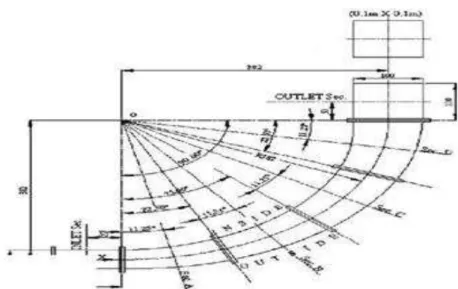
betwe en the sett ling cha mbe r and the in let piec e of the cu rved d iffuser, to prov ide cont inuity as we ll as to acc elerate the flo w. A stra ight in let piec e, 0.lm in length and of c ross-section 0.05m (W I) X 0.lm (b ) was connect ed in bet we en the contract ion p iece and the test diffuser. Th e contract ion p iece , with high cont ract ion rat io , fo llo wed by the stra ight duct at the upstrea m o f the curved d iffuse r ensured un ifo rm flo w to the test diffuse r. Anothe r constant a rea stra ight duct o f cross-section 0.1m X 0.1m and 0.1m in length was p lac ed at the downstrea m o f the test diffuse r to fac ilitat e a cont inuous flo w fro m the d iffuse r outlet so as to min imize the e ffect o f the downstre a m at mosphere . Deta ils of the test diffuse r a long with the in let and out let p ieces are shown in Fig .2. The test diffuse r was fabric ated fro m t ransparent Pe rspe x sheets. The c ross- sectiona l area was inc reased by lin ea rly va ry ing the width fro m 0.05m at in let to 0.l m at the e xit , over the tota l cent re line length of 0.6m wh ile the
height was kept constant at 0.1m. Th e width was equally d istributed norma l to the cente rline . Th e curved d iffuse r was fabricat ed in fou r seg ments each hav ing a 22.5°.So ang le o f tu rn and rad ius of curvatu re 0.382m. For wa ll stat ic p ressure measure ments, the d iffuse rs together with the in let and out let p ie ces we re div ided in s ix sections (In let , A, B, C, D, and Out let ) as shown in Fig.2. Sta in less steel tubes of 2mm OD and 1mm ID we re inse rted and g lued into the 2mm d rilled holes at a ll chosen me asuring stations. In itially a ll the pressure taps we re plugg ed by caps. Fo r measure ment o f static p ressure at a pa rt icu la r station the cap on the steel tube was rep lac ed by a long t ransparent polythen e tube wh ich was connected to one o f the limbs of a mu lt i-tube inc lined d iffe rent ia l mano mete r (inc lined at 35" with the vert ica l) and othe r limbs we re kept open to a 1mosphe re. Kerosene o il was chosen as mano met ric liq uid .
Fig. 1. Sche matic Layout of the Experimental Set-up
Fig .2 . Ge o me t ry o f Cu rve d Diffuse r an d Me asu ring Loc at io ns
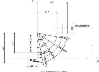
The co mp lete geo metry of curved duct under a test is shown in fig.3. It is a rectangular 90 ° curved duct with 50mm (W ) and height 100mm with centre line length of 600mm (L). It is constituted of
(convex and concave) are fabricated with 3mm thic k perple x sheet. These side walls of the ducts are made by bending the sheet and fastened by screws with the top and bottom paralle l walls. The rad ii of curvature of outer and inner curved walls of duct of radius 407mm and 357mm respectively. The mean radius of the curvature of the duct is 382mm (Rc). Two straight constant area ducts of cross sectional area
50mm X 50mm were attached as extension pieces at the inlet and e xit respectively. The length of the two e xtension pieces are 100mm. They help fixing the inlet and outlet condition of the flow. There are six sections considered at the middle point of these six pieces of rectangular curved duct. These sections are inlet-section, section-A, section-B, section-C, section-D and outlet-section as shown in Fig.3.
Fig .3 . Ge o me t ry o f 90° Cu rved Du ct a nd M easu ring Lo ca t ions
III.
RESULTS AND DISCUSSION
Flow develop ment in the curved flo w passage is a complicate due the influenced by diffe rent geometrica l para meters like total angle of divergence (2θ), angle of turn (Δβ), area ratio (A R), inlet aspect ratio (AS), centreline shape etc. as well as the dynamica l para meters like in let Mach number, inlet turbulence etc. In the present study, experimental investigations have been carried out on curved diffusers to enable a comparative study of the flow development and performance characteristics for diffe rent centre line shapes and different inlet mass averaged velocities. The straight inlet duct, between the contraction section and the test pieces under
investigation, was short (2Wl) and the Inlet Section was located at its mid-length. The flow at the inlet was mostly fully developed with a uniform velocity distribution throughout. At the inlet the mass average velocity is ma intained at 40m/s in both the cases. It is evident that there develops a velocity gradient in the transverse direction for both the C-shaped constant area duct and C-shaped diffuser which is ma inly due to the influenced of the centrifugal action of the centreline curvature and also the same is attenuated in the case of C-shaped diffuser due to the adverse pressure gradient. The Fig. 4 depicts the distribution of mean velocity in the form of 2-D contours.
3.1. Wall
y
StrategyThe wall
y
is a non-dimensional nu mbersimilar to local Reynolds number, determining whether the influences in the wall-adjacent cells are la minar or turbulent, hence indicating the part of the turbulent boundary layer that they resolve.
air air
u
y
y
The wall
y
is a non-dimensional nu mber similar to local Reynolds number, determining whether the influences in the wall-adjacent cells are la minar or turbulent, hence indicating the part of the turbulent boundary layer that they resolve.air air
u
y
y
The subdivisions of the near-wa ll region in a turbulent boundary layer can be summarized as follows (Fluent,2006), [16]:
1.
y
< 5: in the viscous sub layer region (velocity profiles is assumed to be la minar and viscous stress dominates the wall shear)2. 5 <
y
<30: buffer reg ion(both viscous and turbulent shear dominates)3. 30 <
y
< 300: Fu lly turbulent portion or log-law region (corresponds to the region where turbulent shear predominatesThe wa ll
y
is a non-d imens iona l distance s imilar to loca l Reyno lds nu mbe r, o ften used in CFD to describ e ho w co arse o r fine a mesh is for a pa rt icu la r flo w. It is the rat io bet we en theturbulent and la mina r influences in a cell. Very c lose to the wall, viscous damping reduces the tangential velocity fluctuations, while kine mat ics blocking reduces the normal fluctuations. Towards the outer part of the near-wall reg ion, however, the turbulence is rapidly augmented by the production of turbulent kinetic energy due to the large gradients in mean velocity. Accurate presentation of the flow in the near-wall region determines successful prediction of wa
ll-bounded turbulent flows. Va lues of
y
close to thelower bound (
y
≈ 30) are most desirable for wa llfunctions whereas
y
= 1 are most desirable for near-wall mode lling.3.2. Computational methodology and boundary layer condition for C duct
The pre pro cessor GA M BIT is used to create the g eo metry de fin ing the p roble m and descrize the do ma in wh ile FLUENT 6.9 is e mp loyed to descrize and solve the gove rn ing equations. The gene rated mesh size was 105 ce lls. Thre e bounda ry cond it ions are spec ified, i.e . veloc ity in let , p ressure out let and wa ll. No s lip boundary cond itions were applied to the wa lls of the duct. Fo r ve loc ity in let bounda ry cond it ion the turbulent intens ity was taken as 10% and the hydrau lic d ia mete r was taken as 66.67mm where as for pressure out let boundry cond it ion the backflo w modified turbu lent v iscosity was taken as 0.001 m2 /s.
Table 1
RSM
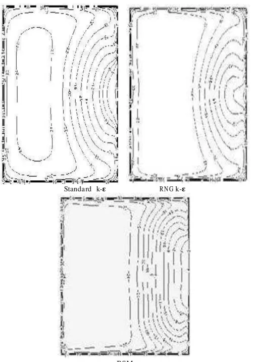
Fig .5 : Mean ve loc ity contou rs at th e outlet section of the C duct
3.3. Computational methodology and boundary layer condition for C diffuser
The pre-processor GAM BIT is used to create the geometry defining the proble m and discretize the domain while FLUENT 6.9 is e mployed to discretize and solve the governing equations. Initially the mesh size of 388311 cells was created Three boundary conditions where specified, i.e. veloc ity inlet, pressure outlet and wall. No slip boundry conditions were applied to the walls of the duct. During the creating of the mesh boundary layer was taken under consideration and the mesh near the walls of the diffuser was dense in comparison with the other region of the diffuser. A turbulence intensity of 6% and a hydraulic dia meter of 0.0666 were taken for inlet and outlet boundary conditions. The standard k-ε, standard k-ωand RSM turbulence models where used and the
y
values were calculated correspondingly. For the case of standard k-ε turbulence model the mesh was adapted according to the Y- plus value. A general method for determin ing the most appropriate mesh configuration is grid independence test, where different meshes are tested until the solution is independent of furtherrefinement, by matching the results to experimental results. But in the present case the method of solution-adaptive refine ment was used, where one can add cells where they are needed in the mesh thus enabling the features of the flow fie ld to be better resolved. When adaption is used properly, the resulting mesh is optimal for the solution because the solution is used to determine where more ce lls need to be added. Here Y-p lus adaption have been provided to appropriately refine or coarsen the mesh along the wall
during the solution process. The minimu m a llo wed
y
value of 2 and ma ximu m allowed
y
was taken to refine the mesh near the wall reg ion. After adapting the grid the mesh size increased to 647031 ce lls. In compressible, 3D steady flow RANS equations imple mented to solve the problem. SIMPLE algorith m was used for the pressure velocity coupling and QUICK scheme was used to discretize the mo mentu m and turbulence equations. Convergence criterion of 0.001 was taken to get a convergedsolution. The wall
Y
values for the different turbulence models considered are as follows:
Standa rd k-� RN G k-�
RSM
Fig .6 : Mean ve loc ity contou rs at th e outlet section of the C d iffusing duct
Fro m both experimental and numerica l results it can be observed that RSM model predicts the flow more efficiently for both the constant area
duct and diffuser. Wall
Y
value at the viscous blending region is lowest and the same at fully turbulent region is highest for the RSM model for the constant area duct, whereas all the three model resolve the viscous sub layer region for C-d iffuser.IV.
CONCLUSION
Fro m both experimental and numerica l results shows that the high mo mentum fluids shifted towards the outer wall due to the generation of secondary motion for both C-shaped constant
area duct and diffusing duct. For constant area duct
based on the
y
parameter RSM turbulence model predicts the flow in a better way and the velocity distribution for the same qualitatively matches with the experimental results. For diffusing duct also RSM turbulence model pred icts the better result
based on the
y
REFERENCES
[1]. R. W . and Kline, S. J., 1962, Flo w Regimes in Cu rved Subsonic Diffusers, Trans A SM E, Jou rna l o f Bas ic Engin ee ring , 84, 303-3
[2]. Sh imizu ,Y., Naga fusa, M ., Sug ino , K., and Na ka mu ra ,F., 1986. Studies on Pe rfo rmanc e and Inte rna l Flo w o f Twisted S-Shaped Bend Diffuser- The So-Ca lled Co iled Bend Diffuser: 1st Report , Trans. A SM E Jou rna l o f Flu ids engine ering 108 289-296
[3]. Sh imizu ,Y., Naga fusa, M ., Sug ino , K., and and Kubota, T., 1986. Studies of UShaped and Sna ke-Shap ed Bend Diffuse rs2nd Repo rt, Trans. o f A SM E Journa l of Flu ids Eng inee ring 108 297-303.
[4]. Sh imizu, Y., Futa ki, Y., and Ma rt in, C.S., 1992. Seconda ry Flo w and Hyd rau lic Losses With in Sinuous Condu its of Rect angular Cross section Trans. o f A SM E Jou rna l of Flu ids Engin ee ring 114 593-600.
[5]. Ma ju md ar, B., Mohan, R., Singh, S.N., and Agra wa l, D.P., 1988. Expe rimenta l Study of Flo w in High Aspect Rat io 90 Deg Cu rved Diffuser Trans. o f ASM E Journa l of Flu ids Eng inee ring 120 83-89.
[6]. El-As ka ry, W .A., and Nasr, M ., 2009. Pe rfo rmanc e of a Bend-Diffuser Syste m: Experiment al and Nu me rica l Stud ies, Journa l of Co mputers & Flu ids 38(1) 160- 170.
[7]. Enayet, M. M ., Gibson, M. M ., Tay lo r, A.M . K. P. and Yiannes kis, M., 1982. Laser Dopp le r measure ments of La minar and Tu rbulent Flo w in a Bend, Int. Jou rna l o f Heat and Flu id Flo w 3 211-217.
[8]. Kim, W . J. and Pate l, V. C., 1994 Orig in and Dec ay of long itud ina l Vo rt ices in the develop ment o f flo w in a cu rved rectangu la r du ct Trans. A SM E, Jou rna l of Flu id Eng ine ering 116(3) 45-5 2. [9]. Lacov ides, H., Laund er, B. E. and
Loizou, P. A ., 1987. Nu me rica l Co mputat ion of Tu rbulent Flo w th rough a Squa red Sect ioned 90° Bend , Int. Journa l of Heat and Flu id Flo w 8(4) 320- 325..
[10]. Ro we, M ., 1970. Measure ments and co mputat ions flo w in p ipe bends, Journa l o f Flu id Mechan ics 43(4) 771-783.
[11]. Singh, N., Singh, S. N. and Seshadri, V., 2004.Flo wCha racte ristics of an
symmet ric Y-Shap ed Duct Proce ed ings of 31st Nat iona l Con fe rence on Flu id Mechan ics and Flu id Po we r, Jadavpu r Uu ive rsity 749-7 57.
[12]. Azzola, J., Hu mpbrey , A . C., Iacov ides, Hand Launde r, B. E., 1986 Deve lop ing circu la r c ross-section : Me asure ment and Co mputat ions, Trans. ASM E, Jou rna l o f Flu id Eng ine ering 108 214-221.
[13]. Bansod, P and Bradsha w, P., 1972. The Flo w in S-shaped Ducts, Ae ronaut ica l Qua rte rly 23 131-140.
[14]. Bu rns, J. M., Fe rubo lz, H. H. and Man ke wit z, P. A ., 1999. An e xpe rimenta l investig ation o f a th ree dimension al tu rbulent boundary laye r in an S-shaped duct , Journ al of Flu id Mechan ics 393 175-213.
[15]. Tay lor, A.M. K. P., Wh ite la w J. H. and Yiannes kis, M ., 1982. Cu rved Du cts with St rong Se condary Mot ion : Ve loc ity Measu re ments of Deve lop ing La minar and Tu rbu lent Flo w, Trans. ASM E, Jou rna l o f Flu id Eng inee ring, I 04 350-358.
[16]. Tbanga m, S. and Hur, N., 1990. La mina r secondary flo ws in curv ed rectangu la r ducts Journa l o f Flu id Mechan ics 217 421-440.