CATALYTIC GENERATION AND STORAGE OF HYDROGEN
FROM HYDROLYSIS OF SODIUM-BOROHYDRIDE
UNDER PRESSURE
APPLICATION IN A HYDROGEN/OXYGEN FUEL CELL
by
Maria Josefina Figueira Ferreira
A dissertation submitted to the Department of Chemical Engineering and to the Department of Mechanical Engineering,
Faculty of Engineering from University of Porto, Portugal, in conformity with the requirements for the degree of Master in Fundamentals and Applications of Fluid Mechanics
This dissertation was supervised by
Dr. Alexandra Maria Pinheiro da Silva Ferreira Rodrigues Pinto, CEFT, Department of Chemical Engineering,
Faculty of Engineering of the University of Porto, Portugal
To my son, Luís
To the memory of my dearly loved grandfather, José da Silva
PREFACE
This dissertation on hydrogen generation from catalytic hydrolysis of sodium borohydride has grown out from the necessity of finishing my Master course in Fundamentals and Applications of Fluid Mechanics, started on the year 2003, at FEUP. After a gap of four years, in early September 2007, I had the privilege of speaking with Dr. Carlos T. Pinho, the Head of the Master course, who offered me the opportunity of working on EDEN’s Project (http://www.h2eden.com) – Task PR07.33.01 – Hydrogen generation via chemical hydrides, on a 8.5 months scholarship, funded by the Agência de Inovação S.A. of Portugal. This was my first experience on the interesting field of clean energies! Dr. Alexandra Pinto, the scientific leader of Task PR07.33.01, with whom I’ve been working since 15 of October 2007, gently accepted my invitation to be the supervisor of this dissertation and I am deeply thankful for that.
Hydrogen generation and storage from chemical hydrides, specifically from sodium borohydride, to fuel hydrogen/oxygen fuel cells is a vast and rapidly evolving research field since the late 1990s. This dissertation does not provide an exhaustive review; my ambition was to write a text that describes one year and half of intensive experimental work and that shows my delight in understanding the catalysed hydrolysis reaction of sodium borohydride (NaBH4), thus closing the old objective of finishing my Master course.
The start of this investigation turned out to be a hard work, because my previous experience on the subject was scarce; but I have been fortunate in having a supervisor who gave me all the support and freedom as the research evolved. Beginning with the aim of “producing and simultaneously storing molecular hydrogen due to solubility’s effects in the remaining solution after NaBH4 hydrolysis completion in a batch reactor” (see Pinto et
al., Int. J. Hydrogen Energy, 31 (2006) 1341-47), the work progresses following three main lines of kinetic experiments: alkali, alkali free and less Polar Organic Polymeric Solutions (lPOPS) hydrolysis of sodium borohydride under pressure. Therefore, three main individual chapters where written, in which the experimental results are shown and
related literature review, and the need for a separate chapter of literature background in the mainly body text was not felt. In this sense, the information in each individual chapter can be understood without the need to read the precedents ones. It is my hope that the readers understand the lines beneath this dissertation and recognize the importance, which is particularly high in portable applications, of producing hydrogen via sodium borohydride hydrolysis, with the goal of feeding a polymer electrolyte membrane (PEM) fuel cell on demand.
At last, a final word for Hydrogen: being the simplest and the most abundant atom both on the Universe and in Earth and having the highest energy to weight ratio (12.24×10⁴ kJ/kg) of all the energy sources known today, are not prime reasons to change energetic paradigm?
Ferreira, M.J.F., University of Porto, Faculty of Engineering, November 2009. Catalytic generation and storage of hydrogen from hydrolysis of sodium borohydride solutions under pressure – application in a hydrogen/oxygen fuel cell. Supervisor: Dr. Alexandra M.F.R. Pinto.
The present dissertation aimed at studying the catalytic generation and storage of hydrogen from hydrolysis of sodium borohydride solutions under pressure. The catalytic hydrolysis of sodium borohydride (NaBH4) was studied under pressure, up to 2.6 MPa, using a reused
ruthenium nickel based powered catalyst, in three batch reactors with internal volumes of 0.645, 0.369 and 0.228 l, made of stainless-steel and positioned vertically. Three different types of sodium borohydride hydrolysis were considered, two of them in the presence of an inhibitor (sodium hydroxide), namely, alkali hydrolysis and also less Polar Organic Polymeric Solutions (lPOPS), and the other in absence of sodium hydroxide, designated by alkali free hydrolysis. The effects of temperature, sodium borohydride concentration, sodium hydroxide concentration, catalyst concentration and system pressure, on the hydrogen gas generation rate, were investigated. Particular importance was given to the effects of reactor bottom geometry on hydrogen generation yields, rates and induction times. Two different geometries were adopted for this purpose - a flat and a conical bottom shapes. The reactor with the conical shape significantly increases the reaction rates and decreases the lag time. Successive loadings of reactant solution with and without magnetic stirring were also presented to evaluate the capability of generating H2 without recharging
the reactor with fresh catalyst.
A detailed characterization of ruthenium nickel based catalyst after 200 reutilizations is presented in terms of textural properties and of morphology. The results reveal some deterioration of the catalyst which leads to slower rates and lower hydrogen yields, but with similar lag time values.
Analysis of reaction by-product by X-Ray Diffractometry revealed the presence of sodium metaborate in alkali hydrolysis and anhydrous borates in lPOPS hydrolysis. The formation of anhydrous borates is particularly important because it increases the gravimetric hydrogen storage density.
During the entire experimental studies, the hydrogen generated by the catalytic hydrolysis of sodium borohydride was used to fuel a PEM fuel cell available at the CEFT research Laboratory to evaluate the capabilities of an integrated solution/application.
Ferreira, M.J.F., Universidade do Porto, Faculdade de Engenharia, Novembro 2009. Produção e contentorização de hidrogénio a partir da reacção de hidrólise catalizada de borohidreto de sódio sobre pressão – aplicação numa célula de combustível a hidrogénio/.oxigénio Supervisora: Professora Doutora Alexandra M.F.R. Pinto.
O objectivo principal desta dissertação foi o estudo detalhado da produção e contentorização de hidrogénio a partir da reacção de hidrólise catalizada de borohidreto de sódio sobre pressão A hidrólise catalisada de borohidreto de sódio foi estudada sobre pressão, até 2.6 MPa, recorrendo a um catalisador em pó à base de níquel, impregnado com ruténio, não suportado, em três reactores de aço inox, com funcionamento por partidas e posicionamento vertical, com volumes internos 0.645, 0.369 and 0.228 l, respectivamente. Três tipos de hidrólise foram considerados – duas delas ocorrem na presença de um inibidor alcalino (hidróxido de sódio) e são designadas como hidrólise alcalina e como hidrólise de solução orgânica menos polar (lPOPS); a terceira ocorre sem a presença deste inibidor e é designada por hidrólise sem hidróxido. Os efeitos da temperatura, concentração do borohidreto de sódio, concentração de hidróxido de sódio, concentração de catalizador e pressão do sistema, na taxa de geração de hidrogénio molecular foram investigados. Foi dada particular atenção aos efeitos da geometria do fundo do reactor no rendimento, taxa e tempo de indução reacional. Duas geometrias diferentes para o fundo do reactor foram selecionadas com este propósitio: uma plana e a outra cónica. Alimentações sucessivas de solução reagente com e sem agitação magnética foram usadas para avaliar a actividade do catalizador.
O catalizador de ruténio à base de níquel após 200 re-utilizações foi caracterizado em termos de textura e morfologia. Os resultados revelaram alguma deterioração do catalizador, traduzindo-se em taxas de produção de hidrogénio e rendimentos de reacção mais baixos, mantendo-se no entanto os tempos de indução.
A análise do produto da reação por difracção de raios X revelou a presença de metaborato de sódio na hidrólise alcalina e de boratos de sódio anidridos na hidrólise de solução orgânica menos polar (lPOPS).
O hidrogénio gerado por hidrólise catalítica de borohidreto de sódio foi usado para alimentar uma célula de combustível de membrana de permuta cateónica, disponível no laboratório do CEFT, para analisar a possibilidade de soluções/aplicações integradas.
ACKNOWLEDGEMENTS
I would like to acknowledge the friends and colleagues at Department of Chemical Engineering at FEUP for their help during this work. In particular, I would like to mention:
Dr. Alexandra M. P. S. F. R. Pinto for her supervision.
Dr. Carlos T. Pinho for the opportunity of introducing me to the very interesting theme of ‘the clean energies, through the conception of 8.5 months scholarship (15Out07 to 30Jun08) of the EDEN’s Project – INEGI Collaboration, financed by ADI of Portugal, under which a great part of this work was carried out.
Dr. Carmen Rangel, from INETI, for catalyst conception and supplying.
Dr. Luís Gales, from IBMC-ICBAS, for his active collaboration in performing the XRD analysis.
Dr. Carlos P. M. de Sá, from CEMUP, for working on XPS-SEM/EDS catalyst characterization, after 200 times of being reused.
Dr. João B. L. Moreira de Campos, for the payment of XPS-SEM/EDS analysis.
Dr. Manuel Fernando R. Pereira, from LCM-DEQ-FEUP, for working on N2 adsorption isotherms (BET) catalyst characterization, after 200 times of being reused.
Eng. Luís Carlos Matos for helping with the data acquisition system. Special thanks to members of CEFT-DEQ-FEUP for laboratory facilities.
I also would like to express my thankfulness to my husband, Pedro Ribeiro, for his constructive criticisms.
DEDICATION III
PREFACE V
ABSTRACT VII
RESUMO IX
ACKNOWLEDGEMENTS XI
LIST OF CONTENTS XIII
LIST OF FIGURES XVII
LIST OF TABLES XXI
NOMENCLATURE XXIII
1 INTRODUCTION 1
1.1 General introduction / 1
1.1.1 Hydrogen as energy carrier / 1
1.1.2 Chemical hydrides as H2 carrier: the particular case of NaBH4 / 4 1.2 Hydrogen/oxygen fuel cell / 7
1.2.1 Polymer Electrolyte Membrane Fuel Cell (PEMFC) / 8
1.2.2 The “MicroBoro Bus” – a didactic demonstration prototype / 10 1.3 Objectives and organization of the dissertation / 11
1.4 Conclusions / 13 1.5 References / 13
2 EXPERIMENTAL TECHNIQUES AND APPARATUS 15
2.1 Introduction / 15 2.2 Materials / 15
2.2.1 Sodium borohydride / 15
2.2.2 Nickel based bimetallic catalyst / 16 2.3 Apparatus for kinetic studies / 19
2.3.1 Reactor design / 19 2.3.2 Experimental rig / 21
2.4 General plan for sodium borohydride hydrolysis experiments / 22 2.4.1 Alkali hydrolysis / 22
2.4.1.1 Successive loadings of reactant solution / 23 2.4.2 Alkali free hydrolysis / 23
2.4.3 Less Polar Organic Polymeric Solutions (lPOPS) hydrolysis / 24 2.5 Reaction products analysis / 25
2.5.1 Molecular hydrogen / 25
2.5.2 Sodium borates by-products / 25 2.6 Conclusions / 26
3.1 Introduction / 27
3.2 Experimental procedure / 32
3.2.1 Effect of reactor temperature on hydrogen generation rate / 32 3.2.2 Effect of NaBH4 concentration on hydrogen generation rate / 33 3.2.3 Effect of NaOH concentration on hydrogen generation rate / 33 3.2.4 Effect of pressure on hydrogen generation rate / 33
3.2.5 Effect of reactor bottom shape on hydrogen generation rate / 34 3.2.6 Effect of successive loadings on catalyst activity/ 34
3.2.6.1 Effect of agitation on hydrogen reaction rate / 35 3.3 Results and discussion / 35
3.3.1 Effect of reactor temperature on hydrogen generation rate / 35 3.3.2 Effect of NaBH4 concentration on hydrogen generation rate / 36 3.3.3 Effect of NaOH concentration on hydrogen generation rate / 37 3.3.4 Effect of pressure on hydrogen generation rate / 37
3.3.5 Effect of reactor bottom shape on hydrogen generation rate / 38 3.3.6 Effect of successive loadings on catalyst activity / 39
3.3.6.1 Effect of agitation on hydrogen reaction rate / 42 3.4 Reaction by-product characterization / 43
3.4.1 Materials and methods / 43 3.4.2 Results and discussion / 43 3.5 Conclusions / 44
3.6 References / 45
4 ALKALI FREE HYDROLYSIS
Results for sodium borohydride kinetic experiments
49 4.1 Introduction / 49
4.2 Experimental procedure / 51 4.3 Results and discussion / 52
4.3.1 Effect of H2O/NaBH4 (mol/mol) on H2 generation yield / 53 4.3.2 Effect of catalyst/NaBH4 (g/g) on H2 generation rate / 56 4.3.3 Effect of pressure on hydrogen generation yield and rate / 56 4.3.4 Effect of reactor bottom shape on hydrogen generation / 58 4.3.5 Effect of temperature on hydrogen generation rate / 60 4.3.6 Gravimetric and volumetric densities / 61
4.4 Reaction by-product characterization / 63 4.4.1 Materials and methods / 63 4.4.2 Results and discussion / 64 4.5 Conclusions / 64
4.6 References / 65
5 less POLAR ORGANIC POLYMERIC SOLUTIONS HYDROLYSIS
Results for sodium borohydride kinetic experiments
67 5.1 Introduction / 67
5.2 Experimental procedure / 69 5.3 Results and discussion / 69
5.4 Reaction by-product characterization / 72 5.5 Conclusions / 75
6.1 Introduction / 77
6.2 Catalyst characterization / 78 6.2.1 Textural properties / 78 6.2.2 Morphology / 81 6.2.3 XPS analysis / 84
6.3 Catalyst activity analysis after 200 reutilizations / 88 6.4 Conclusions / 89
6.5 References / 90
7 CONCLUSION 93
7.1 Conclusions / 93
LIST OF FIGURES
CHAPTER 1
Figure 1.1. Volumetric and gravimetric capacities for several possible H2 storage technologies. [1.3] / 3
Figure 1.2. Status of hydrogen storage technologies. Capacities for both materials-only basis and total
system are shown [1.9]. / 5
Figure 1.3. The first fuel cell, by William Grove (1839). / 7
Figure 1.4. (A) Schematic of a typical H2/O2 PEMFC [1.13]. (B) Nafion® Polymer Electrolyte Membrane Structure and Characteristics. / 9
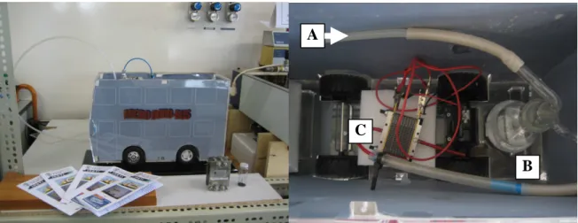
Figure 1.5. Front view and top view of the “MicroBoro Bus” (A – connection to the H2 generator and
storage tank; B- gas-washing bottle; C- PEMFC single cell). / 10
CHAPTER 2
Figure 2.1. Photograph of the nickel based bimetallic catalyst in the form of a finely divided black powder. / 16 Figure 2.2. Photo Scanning electron microscope view of the synthesized catalyst powder (a) and associated elemental analysis EDAX (b). / 17
Figure 2.3. Nitrogen adsorption/desorption isotherms. / 18
Figure 2.4. Photograph of the main batch reactor with the two separate filling pieces used to change the
internal free volume for NaBH4 hydrolysis reactions. / 19
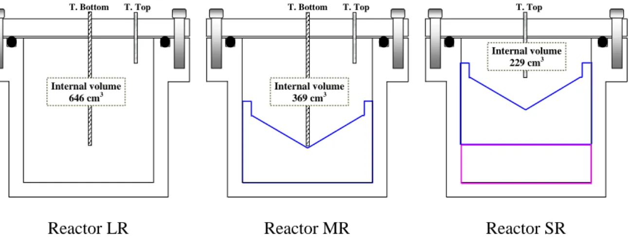
Figure 2.5. Schematic view of the reactors inside: reactor LG – flat bottom, and reactors MR and SR –
conical bottom, with mention of the internal available free volume. / 20
Figure 2.6. Global picture of the experimental setup used for the kinetics studies of hydrogen
production via catalytic hydrolysis of sodium borohydride, under pressure. (1) batch reactor; (2a-2b) data acquisition system; (3) “MicroBoro bus” with a PEM fuel cell; (4) thermostatic bath and (5) refrigeration unit. / 21
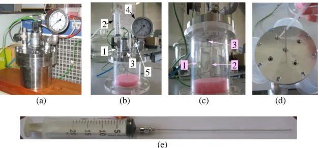
Figure 2.7. Survey picture of the: (a) main reaction vessel / LR; (b) accessories fixed on the outside lid
of the reactor: 1- reactor inlet bore valve, 2- syringe, 3- pressure probe, 4- Bourdon manometer and 5- reactor exhaustion needle valve; (c) ascendant view of the inside lid of the reactor: 1- needle of the syringe, 2- “T.Bottom” k thermocouple and 3- “T.Top” k thermocouple; (d) top view of the inside lid of the reactor showing the left ‘holes’ after connecting the some accessories; (e) syringe with needle (150 mm length). / 22
CHAPTER 3
Figure 3.1. Hydrogen generation plot with a NaBH4 concentration of 10%, an inhibitor concentration of 3%, at different temperatures. The reactions, for 20 cm3 of reactant solution, were performed in the MR batch reactor (369 cm3) with a proportion of Ru-Ni based catalyst/NaBH4: 0.4 g/g. / 35
Figure 3.2. Hydrogen generation plot with an inhibitor concentration of 3%, at 27 ºC, and with different NaBH4 concentrations. The reactions where performed in LR batch reactor (646 cm
3
cm3) with a proportion of Ru-Ni based catalyst/NaBH4: 0.4 g/g. / 37
Figure 3.4. Hydrogen generation with a NaBH4 concentration of 10 wt%, an inhibitor concentration of
7wt%, at 45 ºC, for the three design reactors: LR (646 cm3), MR (369 cm3) and SR (229 cm3). The reactions, for 20 cm3 of reactant solution, were performed with a proportion of Ru-Ni based catalyst/NaBH4: 0.4 g/g. / 38
Figure 3.5. Hydrogen generation plots with a NaBH4 concentration of 10%, an inhibitor concentration
of 7%, at ≈ 26 ºC, for two batch reactors with different bottom shape. The reactions, for 10 cm3 of reactant solution, were performed with a proportion of Ru-Ni based catalyst/NaBH4: 0.4 g/g. / 38
Figure 3.6. Five successive loadings of the reactant solution: 10 wt.% NaBH4, 7 wt.% NaOH, 83 wt.% H2O, with Ni-based/NaBH4: 0.4g/g, performed in the batch reactor LR (646 cm3), showing the temperature profile inside the reactor at two specific points (bottom and top of reactor). / 39
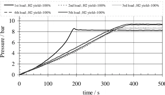
Figure 3.7. Hydrogen generation in batch reactor LR (646 cm3) of five successive loadings of the reactant solution: 10 wt.% NaBH4, 7 wt.% NaOH, 83 wt.% H2O, with Ru-Ni based catalyst/NaBH4: 0.4g/g. / 40
Figure 3.8. Hydrogen generation in batch reactor MR (369 cm3) of seven successive loadings of the reactant solution: 10 wt.% NaBH4, 7 wt.% NaOH, 83 wt.% H2O, with Ru-Ni based catalyst/NaBH4: 0.4g/g. / 41
Figure 3.9. Two images of reaction “gaseous” by-product, after seven successive loadings of reactant
solution (10 wt.% NaBH4, 7 wt.% NaOH, 83 wt.% H2O). The H2 release shows the gas capability to agitate the nickel-based powdered catalyst presented at the reactor liquid phase. / 41
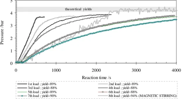
Figure 3.10. Hydrogen generation in batch reactor LR (646 cm3) of eight successive loadings of the reactant solution: 10 wt.% NaBH4, 7 wt.% NaOH, 83 wt.% H2O, with Ru-Ni based catalyst/NaBH4: 0.4g/g (the 8th loading was performed with magnetic stirring). / 42
Figure 3.11. Crystals pictures of the by-product classic hydrolysis of sodium borohydride, obtained by
slow evaporation of a water solution at room temperature (≈ 25 ºC). / 43
Figure 3.12. Views of crystal structure of sodium metaborate dehydrate showing stacking layers formed
by BO3 triangles and by Na and water molecules: (a) view along the a-axis and (b) view along the c-axis. Na in violet, O in red, B in pink and H in white. / 44
CHAPTER 4
Figure 4.1. Pictures showing the preparation of the reactant blend (catalyst plus NaBH4, both solids) to use in alkali free hydrolysis experiments. From left to right: Ru-Ni based catalyst, anhydrous sodium borohydride and the bottom of MR reactor with the mixture (stored in bottom conical shape). / 52
Figure 4.2. Hydrogen generation in the flat bottom batch reactor LR (646 cm3) for experiments with Ru – Ni based catalyst/NaBH4: 0.4 g/g and H2O/NaBH4: 2-8 mol/mol. / 53
Figure 4.3. Hydrogen generation in the batch reactor LR (646 cm3) with Ni-based/NaBH4: 0.4 g/g (27
and 28 times reused) and H2O/NaBH4: 2 mol/mol, after two successive loadings of pure water (of the same molar quantity). / 55
Figure 4.4. Hydrogen yield as a function of added water, H2O/NaBH4 (mol/mol), in batch reactor LG (646 cm3). / 55
Figure 4.5. Influence of the amount of catalyst/NaBH4 (g/g) on hydrogen generation. / 56
Figure 4.6. Hydrogen generation in the studied three batch reactors - LR (646 cm3), MR (369 cm3) and SR (229 cm3), with Ni-Ru based catalyst/NaBH4: 0.4 g/g (111, 150 and 151 times reused, respectively
for LR, MR and SR) and H2O/NaBH4: 4 mol/mol. / 57
Figure 4.7. Influence of pressure on H2 yield (Experiments done in three batch reactors at the temperature range of 289-295 K, with catalyst reused ≈150 times). / 57
temperature range of 289-295 K, with catalyst reused ≈150 times). / 58
Figure 4.9. Photographs of MR reactor (with conical bottom shape) after an alkali free hydrolysis of
NaBH4 experiment. In the right, a view of the solid mixture of the by-product plus the catalyst. / 59
Figure 4.10. Temperature of the hydrolyzed NaBH4 as a function of time by different pressures. / 60
Figure 4.11. Influence of temperature on hydrogen generation rate and yield. / 61
Figure 4.12. View along the c-axis of the crystal structure of sodium metaborate hydrate: (a) 4H2O, in MR at 0.69 MPa and (b) 2H2O, in SR at 1.26 MPa. The element color code, from black to light grey, is B, O, Na and H. / 64
CHAPTER 5
Figure 5.1 Hydrogen generation by a single loading of 20 cm3 of reactant solution, at 45 ºC, with Ni-Ru based catalyst/NaBH4: 0.4 g/g: (a) MR batch reactor [0.369 L] and (b) SR batch reactor [0.229 L]. / 70
Figure 5.2. View along the a-axis of the crystal structure of sodium borate anhydrous, showing the BO4 tetrahedral arrangement and the Na bound network. Na in violet, O in red and B in pink. / 73
Figure 5.3. View along the a-axis of the crystal structure of sodium borate anhydrous, showing the BO3 triangular and the BO4 tetrahedral arrangements sharing oxygen atoms and the Na bound network. Na in violet, O in red and B in pink. / 73
Figure 5.4. Gravimetric H2 storage density (reactants basis) for the three systems studied in this chapter. / 75
CHAPTER 6
Figure 6.1. Nitrogen isotherms of powder Ru-Ni based catalyst 200 times reused. / 80 Figure 6.2. Pore size distributions of powder Ru-Ni based catalyst 200 times reused. / 80
Figure 6.3. SEM micrographs of powder Ru-Ni based catalyst, 200 times reused. Magnifications
between 200 and 100 000X, increasing from (a) to (e). / 82
Figure 6.4. SEM image coupled with EDS spectrum of Ru-Ni based catalyst 200 times reused and a
magnification of 200X. / 83
Figure 6.5. SEM image coupled with EDS spectrum of Ru-Ni based catalyst 200 times reused and a
magnification of 1500X. / 84
Figure 6.6. SEM image coupled with EDS spectrum, at three different selected areas, of Ru-Ni based
catalyst 200 times reused and a magnification of 10 000X. / 85
Figure 6.7. Photograph of Ru-Ni based catalyst 200 times reused pellet, with 10 mm in diameter, for
use in XPS analysis. / 86
Figure 6.8. A survey XPS spectrum of Ru-Ni based catalyst 200 times reused. / 86 Figure 6.9. XPS spectra for Ru-Ni based powdered catalyst 200 times reused. / 87
Figure 6.10. Hydrogen generation plots with a NaBH4 concentration of 10%, an inhibitor concentration of 7%, for two different stages of catalyst reutilization (28 times reused and 200 times reused). The reactions, for 10 cm3 of reactant solution, were performed in LR batch reactor (646 cm3) with a proportion of Ru-Ni based catalyst/NaBH4: 0.4 g/g, at room temperature of ≈ 25 ºC. / 89
LIST OF TABLES
CHAPTER 1
Table 1.1 – Combustion enthalpies for some common fuels [1.2]. / 2 Table 1.2 – FreedomCar requirements stated by the US DOE [1.4]. / 6
CHAPTER 2
Table 2.1 – Textural properties of catalyst powder used in this work before use. / 18 CHAPTER 3
Table 3.1 – Excess hydration factor, x, of aqueous solutions of sodium borohydride. / 28 Table 3.2 – Comparison of gravimetric efficiencies of various reactant preparations. / 29
CHAPTER 4
Table 4.1 - The FreedomCAR targets publish by US Department Of Energy (DOE). / 62
Table 4.2 - Influence of Ni-Ru based catalyst/NaBH4 on gravimetric hydrogen density and
hydrogen yield for H2O/NaBH4: 4 mol/mol. Prediction of the volumetric hydrogen density*. / 63
CHAPTER 5
Table 5.1 – Hydrogen yield for the studied reactant solutions in the two batch reactors and prevision of respective H2 solubility effects, at 45 ºC. / 71
Table 5.2 – Values of conductivity and pH of the studied reactant solutions, before and after reaction completion. / 72
CHAPTER 6
Table 6.1 - Textural properties of powder Ni-Ru based catalyst 200 times reused sample. / 80 Table 6.2 - Specific conditions for XPS analysis of Ni-Ru based catalyst 200 times reused. / 86 Table 6.3 - Results of XPS analysis of Ni-Ru based catalyst 200 times reused. / 88
Table 6.4 - Results for yield, lag time and dP /dtslope in hydrogen generation of 10 mL of 10wt% NaBH4 and 7wt% NaOH solution, at two different stages of Ni-Ru based catalyst reutilization (for
NOMENCLATURE
yield, yield = n(H2)exp / n(H2)theoretical (n= number of moles)
x , excess hydration factor
Vµ , micropore volume by t-method; Vp , total pore volume, for P/P0=0.986. V , molar volume of the liquid t1/2 , the half-life time, min T , absolute temperature, K
Sext , (mesopore + macropore) surface areas by t-method;
SBET ,BET surface area; r , the pore radius
0 / P
P , relative pressure
Greek letters
φ
, contact angle γ , its surface tensionCHAPTER 1
Introduction
In this introductory chapter the topic and main objectives of this dissertation, entitled “Catalytic generation and storage of hydrogen from hydrolysis of sodium borohydride solutions under pressure – application in a hydrogen/oxygen fuel cell” are presented. A general introduction to hydrogen gas as an energy carrier, to sodium borohydride as hydrogen carrier and to polymer electrolyte membrane fuel cells is carried out.
1.1
GENERAL INTRODUCTION
This dissertation investigates a potential improvement to hydrogen (H2) generation and simultaneous storage, by catalytic hydrolysis of sodium borohydride (NaBH4) under pressure, for supply fuel cells of the type PEM – Polymer Electrolyte Membrane.
Due to the accelerate decrease of fossil fuels resources and the continuous growing of energy demand, the development of alternative and clean renewable energy carriers is of the utmost importance. In fact, the world may be even closer to running out of oil than usually admitted [1.1].
The transportation sector and other portable applications are areas where an alternative energy source may have a particularly great impact. Thus, employment of a concentrated energy (electricity) carrier is of vital interest and priority. In this context, hydrogen (H2) is presented as an environmental friendly energy vector, since it may serve as an intermediate through which a primary energy source (for example, solar) can be effectively transmitted and consumed.
1.1.1 Hydrogen as energy carrier
The hydrogen is the simplest and the most abundant atom both on the Universe and in Earth. The supreme important characteristic of hydrogen gas, the lightest and smallest molecule on our planet, is the fact that it has the highest energy to weight ratio, or
gravimetric energy density, of the energy sources known today. Table 1.1, shows the combustion enthalpies for some of the most common used fuels [1.2].
Table 1.1 – Combustion enthalpies for some common fuels [1.2].
fuel reaction energy/mole energy/kg
Ethanol C2H5OH + 3O2→ 2CO2 + 3H2O 1367 kJ 2.97×10⁴ kJ
Coal C + O2→ CO2 393 kJ 3.27×10⁴ kJ
Petroleum 2C8H18 + 25O2→ 16CO2 + 18H2O 5452 kJ 4.47×10⁴ kJ Natural gas CH4 + 2O2→ CO2 + 2H2O 883 kJ 5.50×10⁴ kJ
Hydrogen 2H5 + O2→ 2H2O 247 kJ 12.24×10⁴ kJ
These enthalpic values reflect ideal (100%) combustion at 25 ºC. * Octane is only one of the many hydrocarbons in petroleum. º Methane is the primary constituent (>90%) of natural gas.
As can be seen from the previous table, H2 gravimetric storage density is the highest, 12.24×10⁴ kJ, almost three times more than the average value of the others presented fuels. Additionally, hydrogen as a fuel offers a number of attractive advantages, namely [1.2]:
i) minimal pollution characteristics;
ii) mass transportability comparable to that of petroleum;
iii) combustibility in internal combustion engines (Carnot cycle devices);
iv) feasibility of electrochemical combination with an oxidant in fuel cells (free energy type devices).
Unfortunately, large quantities of molecular hydrogen do not exist in a readily usable form, so it must be synthesized from other energy sources, and then used to transfer energy to another use. For this intrinsic fact, clean and efficient hydrogen production and storage methods still remain a great challenge.
Although the viability of hydrogen combustion, as illustrated in Table 1.1, fuel cells utilization of H2 is potentially even more attractive. In truth, hydrogen can be used directly in a PEMFC to generate electricity, producing water as a by-product. Since a PEMFC operates at lower temperature and offers a higher power density than most fuel cells, it has been widely accepted for use with automobiles and other portable applications. Additionally, fuel cells are noiseless and have no moving parts. However, PEM fuel cell is not free from problems mostly because it requires pure hydrogen. In Section 1.2, below, a more detailed explanation of PEMFC is provided.
A system for production and distribution of H2 will most certainly be dependent on the type of hydrogen storage used. Indeed, hydrogen has a very low volumetric energy density, so it is very difficult to store a sufficient amount of hydrogen in a small and light enough
vessel. In fact, the challenge of hydrogen storage has proved to be the greatest obstacle preventing hydrogen from replacing fossil fuels. Hence, a safe, efficient and economical method of storing hydrogen must be available to implement a hydrogen economy based on renewable resources.
There are presently four main approaches to store and deliver pure H2 gas at the point of use: compressed gas, cryogenic liquid, reversible sorption/desorption, and chemical storage. Each one of these technologies has practical challenges associated with its use. Gravimetric and volumetric capacities of the storage system are the two primary screening criteria. The gravimetric capacity or specific energy is a measure of the usable energy per kilogram of system mass. In practical terms, this quantity is usually expressed as a weight percentage of hydrogen. Volumetric capacity or energy density is the useful energy per litre of system volume. Hydrogen poses unique storage challenges, because it is the lightest and least dense gas, with only 8.98x10⁻⁵kg/L at STP conditions. The current gravimetric and volumetric efficiencies for the four pure hydrogen storage technologies are compared in Figure 1.1 [1.3]. FreedomCAR targets published by US Department Of Energy (DOE) [1.4] for automotive hydrogen storage systems in 2010 and 2015, are also shown.
Figure 1.1. Volumetric and gravimetric capacities for several possible H2 storage technologies. [1.3]
Regarding to the information depicted in Fig.1.1, an alternative to a fossil fuel or metal complex alloy (low H2 density) based hydrogen delivery system, can be offered by inorganic hydride salts – chemical hydrides, and may be utilized as a primary hydrogen
1.1.2 Chemical hydrides as hydrogen carrier: the particular case of NaBH
4Chemical hydrides are materials that produce hydrogen on demand through a chemical reaction with water; and generally, they exhibit greater gravimetric energy densities and are stable during long periods of storage without usage. Among the chemical hydrides, sodium borohydride (NaBH4) is an example of a chemical hydride that has the advantage of storing hydrogen in a stable and safe solution. Its hydrogen content is of 10.6 wt%, what makes itself one of the highest hydrogen containing compounds.
Sodium borohydride reacts with water to generate molecular hydrogen according to the hydrolysis reaction shown in equation (1.1):
NaBH4 + (2+x) H2O → NaBO2.xH2O + 4 H2 + heat. (1.1)
The standard state enthalpy change of the above reaction at 25 ºC is -217 kJ and is therefore exothermic [1.5]. Unluckily, the rate of hydrogen release during the hydrolysis reaction is low due to the increase of the solution pH as the basic metaborate (NaBO2) by-product is formed. Schlesinger et al. [1.5] recognized the particular striking catalytic effect of certain transition metals and their salts on sodium borohydride hydrolysis rate. Regarding to equation (1.1), ideal hydrolysis is attained for x=0 [1.5], but in practice excess of water is required accounting for the fact that the solid by-product (NaBO2.xH2O) can exist with varying degrees of hydration [1.6]. Lyttle et al. [1.7] observed that commercial borohydride deteriorates rapidly in aqueous solution, but is fairly stable in basic solutions and furthermore the higher the pH the greater the stability. This finding turned the solution pH as the limiting parameter of reaction (1.1) and forced researchers to find a practical and controlled way of producing hydrogen by using catalysts or small amounts of acid. Hence, heterogeneous catalysis offers a number of advantages: independence of solution pH over a wide range, controllable hydrolysis rate and the reuse of the catalyst.
In fact, hydrogen storage density of sodium borohydride can be calculated in several ways, depending on the compound on which the weight density of hydrogen is based on. For instance, the hydrogen storage capacity of sodium borohydride is 10.92 wt% by weight and can be calculated by dividing the molar mass of hydrogen produced by the total molar mass of NaBH4 plus the molar mass of the stoichiometric amount of water needed for reaction (ideal hydrolysis, x=0). As mentioned before, a PEMFC produces water as a
by-increases to 21.3 wt% [1.8]. However, one important factor to regard is that the by-product of the chemical reaction (1.1) is still carried on-board. Hence, it must be included in the storage density calculations. If so, the H2 storage density drops from 21.3 wt% to 12.2 wt%. As previously stated, the solid by-product, NaBO2, can exist with varying degrees of hydration (NaBO2.xH2O), such as the tetrahydrate metaborate, NaBO2.4H2O. In this case, the hydrogen storage density decreases to a level ≈ 4 wt%.
The US Department Of Energy (DOE) has published FreedomCAR requirements for automotive hydrogen storage systems [1.4], probably the most stringent targets yet articulated for hydrogen storage systems. These specifications are based on system mass and volume, i.e., not only the storage material itself (materials-only basis) but also the reactors, tanks, valves, and all supplementary equipment, which usually are call hardware.
In Figure 1.2, below, emphasis is given to chemical hydrides as materials with effective high H2 storage capacities. The position of the several chemical hydrides shown in that plot is calculated for materials-only basis.
NaBH 4 NaBH 4 NaBH 4
Figure 1.2. Status of hydrogen storage technologies. Capacities for both materials-only basis and total
system are shown [1.9].
As illustrate in the previous figure, chemical bonding of hydrogen is the only available storage technique that can produce energy densities approaching to the FreedomCAR targets. The potential of sodium borohydride system to meet these targets on a
reactant-only basis is highlighted and can be evaluated using the stoichiometry of equation (1.1). As stated before, for the case of ideal hydrolysis (x = 0), the hydrogen storage capacity is 10.92 wt% or 0.1092 kg H2/kg reactants. Therefore, the hydrolysis of NaBH4 has the potential to meet FreedomCar 2015 requirements (0.09 kg H2/kg system) for specific energy if x is close to zero.
The mass that can be allocated for the hardware components can be estimate from the FreedomCar targets and the calculated reactant-only specific energy. To compute the mass that can be allocated for hardware, the FreedomCar 2015 target is compared to the maximum theoretical specific energy, as shown below [1.6]:
reactants kg hardware kg 2 . 0 y system kg 1 H kg 09 . 0 hardware kg y reactants kg 1 H kg 1092 . 0 2 = 2 ⇔ = + . (1.2)
As shown in (1.2), for NaBH4 with x=0, the allowable hardware mass is 0.2 kg of reactor per kg of reactants, or 17% of the total system mass. As x increases, the allowable component mass decreases until, at a value of x= 0.84, it is no longer possible to meet the FreedomCar 2015 requirements. Hence, for an excess hydration of 2 the allowable reactor mass is negative. This means that is not possible to design a reactor that meets the FreedomCAR 2015 target if x=2. Table 1.2 shows the FreedomCar requirements for specific energy density for the years 2010 and 2015, along with the allowable excess hydration factor based on sodium borohydride hydrolysis [1.6]. Similar calculations can be done for the other FreedomCar targets.
Table 1.2 – FreedomCar requirements stated by the US DOE [1.4].
Year 2010 2015
Usable specific energy from hydrogen Target (kWh/kg system) Target (kg H2/kg system) 2.0 0.06 3.0 0.09
Usable energy density from hydrogen Target (kWh/L system) Target (kg H2/m3 system) 1.5 45 2.7 81
Allowable excess hydration factor based on NaBH4 hydrolysis
x (reactants basis) 3.31 0.84
Allowed reactor mass ratio (reactor mass/mass of reactants) x = 0 x = 2 0.807 0.214 0.204 -0.190
We may conclude if x= 2 or even 4 the materials-only storage capacity is still promising for some other niche of applications [1.10]. But, in practice to date the best systems require that the NaBH4 be pre-dissolved in a large excess of water; the excess water and the mass of the system equipment, significantly reduce the storage efficiency. However it is of great interest to determine the amount of structural water that remains bound to the metaborate product, for example, by X-Ray Diffractometry.
1.2
HYDROGEN/OXIGEN FUEL CELL
Fuel cells are not a new invention. In fact, the first recorded fuel cell utilized carbon and nitric acid as fuel and was constructed in 1801 by Sir Humphrey Davy. The accreditation for the invention of the fuel cell, however, is awarded to William Grove, who in 1839 used hydrogen and oxygen to produce electricity. Grove discovered that by arranging two platinum electrodes with one end of each immersed in a container of sulphuric acid and the other ends separately sealed in containers of oxygen and hydrogen, a constant current would flow between the electrodes. The sealed containers held water as well as the gases, and he noted that the water level rose in both tubes as the current flowed. Grove realized that combining several sets of these electrodes in a series circuit he might “effect the decomposition of water by means of its composition”. Then after, he gave the name of a ‘gas battery’ – the first fuel cell (see Figure 1.3) [1.11].
Figure 1.3. The first fuel cell, by William Grove (1839).
The fuel cell invented by Grove stimulated research in nineteen century, but no practical applications was developed. In twentieth century, during World War II, the british scientist
Francis Bacon designed the first alkaline fuel cell. In the 1960s, NASA showed some of the potential applications for fuel cells by using them to provide power on space missions.
Currently, five types of fuel cells are receiving attention for energy production in stationary or transportation applications. These are Alkaline Fuel Cells (AFC), Molten Carbonate Fuel Cells (MCFC), Phosphoric Acid Fuel Cells (PAFC), Solid Oxide Fuel Cells (SOFC), and Polymer Electrolyte Membrane Fuel Cells (PEMFC). All of these fuel cell types have been demonstrated as stationary power plants with the advantage of providing high quality on-site electrical power. The last decade has focused primarily on using PEMFC’s for transportation purposes. Fuel cells also have the benefit of producing constant amounts of electrical energy.
Hydrogen is the ideal fuel for fuel cells. In all types of fuel cells mention in the above paragraph, hydrogen exhibits fast reaction kinetics and the only by product of the reaction when oxygen is used as the oxidant is water.
1.2.1 Polymer Electrolyte Membrane Fuel Cell (PEMFC)
Polymer Electrolyte Membrane Fuel Cells (PEMFCs) have been the focus of a great deal of research in the last few years due to the increasing demand for clean power that can be supplied from a lightweight system. PEMFCs fall into this category due to their membrane electrode assemblies (MEA). The MEA is sandwich composed of three different layers. The first layer is the catalyst material, which consists of platinum particles (Pt) loaded into a carbon cloth support. The next layer is the PEM. Although there are a few different types of PEM materials, the industry standard is a copolymer of tetrafluoroethylene and perfluoro[2-(fluorosulfonylethoxy)propylviny] ether. This material has a trade name, Nafion®, and is made by DuPont [1.12]. The third layer is another Pt loaded catalyst layer usually of the same composition as the first catalyst layer, depending on the fuel types. The typical MEA is roughly 0.02’’ thick, and has negligible weight. Since the cell operates at temperatures below 100 ºC, the shell of the fuel cell can be made out of lightweight plastics. These characteristics make the PEMFC ideal for transportation power applications. Figure 1.4 shows a typical PEMFC [1.13] and the chemical structure for Nafion® Polymer Electrolyte Membrane Structure from DuPont.
The circled portion within Figure 1.2 shows the MEA.
The Polymer Electrolyte Membrane (PEM) is responsible for transporting the hydrogen ion produced through catalysis at the anode to the cathode, where it recombines with
oxygen ions and electrons to form water. The transport of the hydrogen ion, a proton, is made possible by the structure of Nafion®.
(A) (B)
Figure 1.4. (A) Schematic of a typical H2/O2 PEMFC [1.13]. (B) Nafion® Polymer Electrolyte Membrane
Structure and Characteristics.
The blue section is a Teflon-like, fluorocarbon backbone that has hundreds of repeating CF2-CF2-CF2- units. The brown section (vertical section of the molecular chain) is a side chain that connects the backbone to the sulfonic acid ions. The SO3- anions are permanently attached, but the H+ ions become mobile upon hydration of the membrane.
Thus, for a fuel cell to be functional, the fuel must be hydrated before entering the cell. For hydrogen, this is done by running the gas through a washing bottle. In the case of methanol or ethanol, the alcohol is in a water solution. The ion exchange capacity of Nafion® is 0.91meq/g (equivalent hydrogen mass per mass of dried Nafion®) [1.12].
In brief, the electrochemical reactions within an electrochemical cell are segregated to two half cells, where an electrochemical reaction occurs at each half cell. Therefore, the half cell reactions of a hydrogen/oxygen fuel cell, in an acidic electrolyte, are
Cathode: 2 1 O2 + 2H+ + 2e-→ H2O- (1.4) Overall: H2 + 2 1 O2→ H2O- (1.5)
The future of hydrogen as an energy carrier will be determined by the oil market and the price that society is willing to pay for an energy supply that is poor in carbon dioxide. The costs of hydrogen production are, for the time being, prohibitive of any introduction into the energy market. As soon as the world energy price permits, the hydrogen/electricity combination will be open to an interesting future.
1.2.2 The “MicroBoro Bus” – a didactic demonstration prototype
The hydrogen generated in the experiments performed during this dissertation, was supplied to a PEMFC single cell that was housed in a bus like shaped mobile platform, used for didactic proposes – the “MicroBoro Bus” [1.14]. Figure 1.5 shows two pictures, a side view and a top view, of the Microboro Bus. The single cell was fed with hydrogen generated by the catalytic hydrolysis of NaBH4 experiments.
The developed low power PEM fuel cell uses an air breathing cathode and humidified hydrogen produced by the borohydride reactor. Natural convection to air feed the cathode is used when the platform is located on a stand and the energy conversion required is just the one needed to make the wheels of the platform turn. Forced convection, by means of a fan, supplies air to the cathode when the platform as a whole is programmed to move. The necessary energy to drive the fan is provided by the fuel cell [1.14].
Figure 1.5. Front view and top view of the “MicroBoro Bus” (A – connection to the H2 generator and storage
C
B A
1.3 OBJECTIVES AND ORGANIZATION OF THE DISSERTATION
It is the objective of the present research to better understand the kinetic mechanism of catalysed hydrolysis of sodium borohydride for producing molecular hydrogen at elevated yields and rates, with high gravimetric and volumetric hydrogen densities. Hence, three main different series of kinetic experiments of hydrolysis of sodium borohydride under pressure, in the presence of reused nickel-ruthenium based catalyst, were carried out to achieve this goal.
The present dissertation evaluates the following objectives:
1) Perform catalysed hydrolysis reactions of sodium borohydride in three different ways: - by joining an alkali to sodium borohydride solutions – alkali hydrolysis;
- without joining an inhibitor – alkali free hydrolysis;
- by joining an organic polymer or surfactant – lPOPS hydrolysis,
to understand deeply the kinetic and chemistry of the hydrolysis and to investigate the influence of pressure, temperature and reactant concentrations on the reactions rates and yields;
2) Verify the influence of reactor bottom shape on hydrogen generation yields and rates; 3) Produce hydrogen by the concept of successive loadings of reactant solution;
4) Analyze the influence of magnetic stirring in refuelling hydrolysis;
5) Study the catalyst reutilization/durability and performance/capacity, after 200 times of being used;
6) Characterise the catalyst, in terms textural properties, morphology and XPS analysis, after a long period of reutilization.
The organization of the dissertation involves eight chapters concerned with: Chapter 1, Introduction
Introduces the research topic and present the main objectives of this dissertation, entitled “Catalytic generation and storage of hydrogen from hydrolysis of sodium borohydride solutions under pressure – application in a hydrogen/oxygen fuel cell”. Short reviews of hydrogen as a energy carrier, sodium borohydride as hydrogen carrier and PEM fuel cells are presented.
Chapter 2, Experimental techniques and apparatus.
In this chapter the materials used in all the experimental studies are described, including the nickel based bimetallic catalyst. For the latter, a textural and morphological characterization is provided. The experimental rig, with special emphasis given to the
Chapter 3, Alkali hydrolysis/Results for sodium borohydride kinetic experiments.
This chapter presents the results of alkali hydrolysis of sodium borohydride in the presence of a reused nickel based bimetallic catalyst. The effects of temperature, NaBH4 concentration, NaOH concentration, and system pressure and reactor bottom shape on the hydrogen generation rate are investigated. Particular importance is given to the effect of successive loadings of reactant on catalyst activity, with and with out magnetic stirring. Selected XRD analysis for the reaction by-product is also presented.
Chapter 4, Alkali free hydrolysis/Results for sodium borohydride kinetic experiments. This chapter shows the results obtained on alkali free hydrolysis of sodium borohydride in the presence of a reused nickel based bimetallic catalyst. A discussion on the stoichiometry of hydrolysis, in terms of the number of added water molecules to solid NaBH4, is carried out, based on the results of hydrogen generation rate and yields. Emphasis is given to reactor bottom design effects on the hydrogen production. The reaction by-products are analysed by XRD.
Chapter 5, less Polar Organic Polymeric Solutions for sodium borohydride kinetic experiments.
This chapter illustrates the results obtained on lPOPS hydrolysis of sodium borohydride plus small additions of an organic polymer and surfactant, in the presence of a reused nickel based bimetallic catalyst. With the aim of improve the solubility of H2 in the remaining solution, a discussion of the results of hydrogen generation rate and yields is carried out. The reaction by-products are analysed by XRD.
Chapter 6, Nickel based bimetallic catalyst characterization / results after 200 reutilizations.
This chapter focuses on the characterization of the nickel based bimetallic catalyst after 200 reutilizations. Textural properties based on nitrogen adsorption isotherms; surface morphology by scanning electron microscopy (SEM) coupled with EDS spectroscopy and X-ray photoelectron spectroscopy (XPS) analysis, were used to characterized the powder catalyst.
Chapter 7, Conclusion.
This chapter is devoted to conclusions and suggestions for future work. Conclusions drawn from the results indicate that the reused ruthenium nickel based catalyst is capable of catalyzing the sodium borohydride solutions at sufficient rates, in the three schemes presented in this dissertation for comparison – alkali hydrolysis, alkali free hydrolysis and
1.4 CONCLUSIONS
High performance fuel cells rely on a source of hydrogen for operation. Distribution of hydrogen either in the gaseous or liquid state is energy intensive and requires extensive infrastructure development to become a safe and reliable source of energy.
In this introductory chapter a short literature survey identified hydrogen gas as energy carrier and chemical hydrides as high density hydrogen carriers. Special emphasis was given to sodium borohydride which is stable in basic solution and can easily be manipulated. The inherent capacity for on-site hydrogen generation further enhances the projection for NaBH4 as hydrogen vector for supplying hydrogen/oxygen fuel cells. Hence, a briefly outline of PEM fuel cells was also exposed.
Finally, the feasibility of borohydride source hydrogen in an operational PEM fuel cell has been established. In truth, the hydrogen generated in the experiments performed during this dissertation, was supplied to a PEM single fuel cell that was housed in a bus like shaped mobile platform, used for didactic proposes – the “MicroBoro Bus” [1.14]
1.5 REFERENCES
[1.1] ‘Crucial data distorted as global oil runs dry’, The Guardian weekly, 13-19 Nov. 2009.
[1.2] ‘Catalytic generation of hydrogen from the hydrolysis of sodium borohydride. Application in a hydrogen/oxygen fuel cell. C.M. Kaufman, PhD Thesis, 1981.
[1.3]http://www1.eere.energy.gov/hydrogenandfuelcells/storage/tech_status.html.
[1.4] U.S. Department of Energy Hydrogen Program. Available from: http://www.hydrogen.energy.gov/ .
[1.5] H.I. Schlesinger, H.C. Brown, A.E. Finholt, J.R. Gilbreath, H.E. Hoeskstra, K. Hyde, Sodium borohydride, its hydrolysis and its use as a reducing agent and in the generation of hydrogen, J. Am. Chem. Soc. 75 (1953) 215-219.
[1.6] E. Marrero-Alfonso, J.R. Gray, T.A. Davis, M.A. Matthews, Hydrolysis of sodium borohydride with steam, Int. J. Hydrogen Energy 32 (2007) 4717-4722; Minimizing water utilization in hydrolysis of sodium borohydride: the role of sodium metaborate hydrates, Int. J. Hydrogen Energy 32 (2007) 4723-4730.
[1.7] D.A. Lyttle, E.H. Jensen, W.A. Struck, A simple volumetric assay for sodium borohydride, Analytical Chem. 24 (1952) 1843-1844.
[1.8] V.C.Y. Kong, F.R. Foulkes, D.W. Kirk, J.T. Hinatsu, Development of hydrogen storage for fuel cell generators. I – Hydrogen generation using hydrolysis hydrides, Int. J. Hydrogen Energy 124 (1999) 665-675.
[1.9] A. Züttel, P. Wenger, S. Rentsch, P. udan, Ph. Mauron, Ch. Emmenegger, LiBH4 a new hydrogen storage material. J. Power Sources 118 (2003) 1-7.
[1.10] U.B. Demirci, O. Akdim, P. Miele, Ten-year efforts and a no-go recommendation for sodium borohydride for on-board automotive hydrogen storage, Int. J. Hydrogen Energy 34 (2009) 2638-2645.
[1.11] W.R. Grove, Phi. Mag,14 (1839) 127.
[1.12] DuPont, Nafion® perfluorinated polymer products, Product Information Guide, 2000.
[1.13] European Fuel Cell GMBH, 2005.
[1.14] Rangel C.M., Silva R.A., Pinto A.M.F.R. Fuel cells and on-demand hydrogen production: didactic demonstration prototype. Proceedings of the International Conference in Power Engineering and Electric Drives”, Eds. L.S. Martins and P. Santos, Setúbal, Portugal, September 12-14, 2007, paper 237.
CHAPTER 2
Experimental techniques and apparatus
In this chapter the materials used in all the experimental studies are described, including the nickel based bimetallic catalyst, the experimental setup with special emphasis to the reactor design, and also a brief mention of reaction products analysis.
2.1 INTRODUCTION
A detailed description of the materials used in the kinetic studies of the catalytic hydrolysis of sodium borohydride is presented, both for the reactant solutions and for the nickel-based bimetallic catalyst. The methods of preparation of the reactant solutions and/or pre-treatment of the catalyst, the experimental rig design and detailed experimental plan for three different kinds of kinetics studies: alkali hydrolysis, alkali free hydrolysis and less Polar Organic Polymeric Solutions (lPOPS) are presented. The techniques used for reaction products analysis: pure molecular hydrogen and sodium borates by-product are also mentioned.
2.2 MATERIALS
2.2.1 Sodium borohydride
Anhydrous sodium borohydride powder (96% purity) was provided by MERCK (No.: 1.06371.0100) and stored in a dessicator until use.
In the experiments with the fuel (NaBH4) in the liquid form, used in alkali hydrolysis and in lPOPS hydrolysis, the reactant solutions were stabilized by the addition of small quantities of sodium hydroxide pellets as a hydrolysis inhibitor. The sodium hydroxide
(98% purity) was supplied by EKA (No.: 1310.73.2). Deionised water was used to prepare all the aqueous reactant solutions and, in all of them, the initial pH was approximately 14.
In the experiments with alkali free hydrolysis of NaBH4 for hydrogen generation, the
anhydrous sodium borohydride powder was used in the solid state.
2.2.2 Nickel based bimetallic catalyst
The catalyst used in all the experiments reported in this dissertation is a nickel based bimetallic catalyst, synthesized at LNEG – Laboratório Nacional de Energia e Geologia, Fuel Cells and Hydrogen Unit, Lisbon – Portugal.
Catalyst preparation
The catalyst, in the form of a finely divided black powder (see Figure 2.1), unsupported, was prepared from a mixture of precursors in deionised water - impregnating small quantities of ruthenium in the nickel salts (Riedel-de Haën) - by chemical reaction with 10 wt% stabilised borohydride solution (Rohm and Haas), as the reducing environment. When the reduction was complete the catalyst was appropriately decanted, washed, filtered, dried and heat-treated at 110ºC. The catalyst was kept in a dessicator until use.
Figure 2.1. Photograph of the nickel based bimetallic catalyst in the form of a finely divided black powder.
Catalyst samples were analyzed for textural properties. The determination of surface areas (SBET), by N2 physisorption was undertaken at 77K, using a Quantachrome Instruments Nova 4200e apparatus. Prior to the analysis, the samples (0.127 g) were degassed at 160 ºC for 3 h. Pore size distributions were obtained from the desorption branch of the isotherms using the Barrett, Joyner and Halenda (BJH) method. The micropore volumes and mesopore surface areas were determined by the t-method.
Morphology and elemental composition analysis of the catalyst were done on a Scanning Electron Microscopy (SEM) coupled with EDS unit FEI Quanta 400 FEG ESEM/EDAX Genesis X4M operating at 15 kV in low vacuum mode (LVSEM for uncoated non conductive sample). The powder sample was prepared by simple dispersion over a double side adhesive carbon tape. X-Ray Photoelectron spectroscopy (XPS) of the catalyst before use, after the powder sample was made into a pellet of 10 mm diameter, was carried out on a VG Scientific ESCALAB 200 A spectrometer using Mg Kα (1,253.6 eV) as a radiation source. The photoelectrons were analysed at a takeoff angle of 0º.
Catalyst characterization before used
The catalyst used in this work is a powder containing Ni and Ru species with nanometric particle size, as evident in Figure 2.2a). The amount of ruthenium is small and was not detectable by EDAX, see Figure 2.2b). However, by XPS analysis less than 1 At% Ru was indicated. (a) C o u n ts ( a. u ) (b) (a) Energy (keV)
Figure 2.2. Photo Scanning electron microscope view of the synthesized catalyst powder (a) and associated elemental analysis EDAX (b).
The nitrogen (N2) adsorption and desorption data as a function of pressure (at liquid nitrogen temperature) are displayed in Figure 2.3. The results shows that de N2 isotherm
shape is of type IV, validating the BJH method used for characterized the textural properties of our powder catalyst. Total specific surface area, as determined by N2 physisorption, gave a value of 54 m2g-1 and negligible micropore volume. In Table 2.1 the textural properties of Ni-Ru based catalyst before used are summarized.
0 20 40 60 80 100 120 140 160 0 0,2 0,4 0,6 0,8 1 Relative Pressure (P/P0) V o lu m e ( c m 3/g )
Figure 2.3. Nitrogen adsorption/desorption isotherms.
Table 2.1 – Textural properties of catalyst powder used in this work before use. Catalyst SBET / m
2
g-1 Vµ / cm3 g-1 Sext / m2 g-1 Vp / cm3 g-1
Before use 54 0 52 0.22
SBET = BET surface area;
Vµ = micropore volume by t-method;
Sext = (mesopore + macropore) surface areas by t-method;
Vp = total pore volume
After some preliminary hydrolysis rate tests with different proportions of Ni-based bimetallic catalyst/NaBH4, it was decided that the appropriate relation to use in most of the
experiments reported in this dissertation is Ni-based bimetallic catalyst/NaBH4: 0.4 g/g.
After the first utilizations, the consequent kinetic experiments were done with reused catalyst. The procedure adopted for the reutilization of the catalyst was to recover it from the remaining solution in the reactor, to wash it five times with distilled water, then carry out sedimentation by gravity for complete physical separation from distilled water, and finally, dry the catalyst in an oven at 60 ºC for four hours.
2.3 APPARATUS FOR KINETIC STUDIES
2.3.1 Reactor design
The hydrolysis reactions were carried out in batch reactors, especially designed for the experiments reported in this dissertation, all of them performed at pressures up to 3MPa. The main batch reactor has an internal volume of 646 cm3 and was made of stainless steel AISI 316, with wall width equal to 10 mm. Special care was taken with the value of the wall width during the reactor design because all the kinetic experiments were to be done at high pressures. As it is well known, hydrogen dissolution and permeation can be significant at high pressure through most of materials, including stainless steels. This may affect the integrity of structural components used for H2 storage during reaction, since hydrogen can embrittle metals [2.1]. In order to allow for changes in the internal volume of the main reactor, another two separate filled pieces that can be introduced inside the main vessel without gap were designed and constructed as well in stainless steel AISI 316. The three possible final design combinations of interest result in three different batch reactors, named LR, MR and SR, with internal free volumes of 646 cm3, 369 cm3 and 229 cm3, respectively. Figure 2.4 shows a photograph of the main reaction container with the two different separate filled pieces.
Figure 2.4. Photograph of the main batch reactor with the two separate filling pieces used to change the
internal free volume for NaBH4 hydrolysis reactions.
In comparison with the reactor used on an earlier work [2.2], two major improvements were made in the reactor design. The upgrading is related with the reactor sealing, i.e., an
possibility of following the reaction temperature at two different cottas inside the vessel by using two k thermocouples positioned at two distinct points: one near its bottom (named T.Bottom) and the other one very close to its top (named T.Top). The first one is used to monitor the increase of temperature in the core of the exothermic catalytic reaction, and
the second one, simply measures the temperature of molecular hydrogen in the free volume of the container opened for the gas.
With the objective of studying the possible effect of the reactor bottom shape on the hydrogen generation rates - this constitutes one of the originalities of the present
dissertation, an inside flat bottom and a conical bottom geometry were designed, to enable non-dispersible effects during the contact of the fine powder catalyst either with the reactant solutions or with the solid NaBH4 plus the injected pure water, the latter in the
alkali free hydrolysis experiments. Figure 2.5 show the exposed view of the inside designed reactors. Internal volume 646 cm3 T. Bottom T. Top Internal volume 369 cm3 T. Bottom T. Top Internal volume 229 cm3 T. Top
Reactor LR Reactor MR Reactor SR
Figure 2.5. Schematic view of the reactors inside: reactor LG – flat bottom, and reactors MR and SR –
2.3.2 Experimental rig
An overview photograph of the experimental rig is offered in Figure 2.6.
Figure 2.6 Global picture of the experimental setup used for the kinetics studies of hydrogen production via
catalytic hydrolysis of sodium borohydride, under pressure. (1) batch reactor; (2a-2b) data acquisition system; (3) “MicroBoro bus” with a PEM fuel cell; (4) thermostatic bath and (5) refrigeration unit.
The typical hydrogen generation experiments involve the preparation of the reacting solution by adding the appropriate amount of NaBH4 to a certain volume of aqueous solution of the inhibitor NaOH (with a chosen hydroxide concentration) in the case of the alkali hydrolysis or, a certain molar quantity of pure water, in the case of the alkali free hydrolysis. After perfectly sealing the reaction autoclave, an adequate volume of reacting solution (or pure water) is rapidly injected into the reactor by means of a syringe with a large needle length (150 mm), to ensure that the reacting solution (or distilled water) is delivered very close to the nickel-based bimetallic powder catalyst. This catalyst has been previously stored in the bottom of the reactor, in a proper quantity, measured in an analytical balance.
The temperature of the reactor medium was monitored at two different points, as mentioned above, and recorded simultaneously with a data acquisition system (see 2a and 2b in Fig.2.6), using Labview software. To monitor the rate of hydrogen generation, using the same data acquisition system, the gas pressure inside the reactor was followed with an appropriate pressure transducer calibrated from 0-40 bar gauge and also by a Bourdon manometer (from 0-60 bar gauge), until attaining a constant pressure inside the reactor. An overview of the instrumentation fixed on the cover of the reaction chamber is offered in

![Figure 1.2. Status of hydrogen storage technologies. Capacities for both materials-only basis and total system are shown [1.9].](https://thumb-eu.123doks.com/thumbv2/123dok_br/15002191.1010001/29.892.185.743.572.943/figure-status-hydrogen-storage-technologies-capacities-materials-basis.webp)
![Figure 1.4. (A) Schematic of a typical H 2 /O 2 PEMFC [1.13]. (B) Nafion® Polymer Electrolyte Membrane Structure and Characteristics](https://thumb-eu.123doks.com/thumbv2/123dok_br/15002191.1010001/33.892.171.700.203.584/figure-schematic-typical-polymer-electrolyte-membrane-structure-characteristics.webp)