UNIVERSITY OF BEIRA INTERIOR
Effects of Intercooling and Regeneration in the
Performance of a Turbofan Engine
João Lebre
Supervisor
Prof. Francisco Brójo
This thesis is submitted to University of Beira Interior
in partial fulfillment of the requirements for the degree of Master of Science
Faculty of Engineering
Department of Aerospace Science
i
Abstract
The modern aviation is being questioned due to high emission of gases in the atmosphere. The introduction of heat exchangers for engines with two spools could be one of the solutions to this problem. One of the heat exchangers is the intercooler that is intended to cool the air when it leaves the low pressure compressor. After cooled air enters the high pressure compressor, causing a decrease in the compression work of the high pressure compressor. The other heat exchanger is the regenerator which is located in the hot nozzle. This exchanger, heat the air before entry in the combustion chamber. The air exits the high pressure compressor and it is heated by the exhaust gases before entering the combustion chamber. This increase in temperature causes a decrease in specific fuel consumption. These two components are already used in ground power plants and they were not used in aircraft because of the extra weight and size. The use of the heat exchangers could be justified, if the reduction in the specific fuel consumption and increase of efficiency and specific thrust are worthwhile when compared to the penalty introduced by the extra weight. In this work is compared the performance parameters of a conventional engine with the ones of three configurations intended to increase the global performance of the engine. These three configurations use intercooler, regenerator or both. The comparison is performed to show the influence of engine parameters in specific fuel consumption, specific thrust and thermal efficiency. So it shows which is the best engine configuration to be used for the lower specific fuel consumption with the same specific thrust of the conventional engine.
Keywords: heat exchangers; turbofan; intercooler; regenerator.
ii
Resumo
A aviação moderna está a ser questionada pelas emissões de gases poluentes na atmosfera. A introdução de permutadores de calor em motores com dois veios tem sido uma das soluções para este problema. Um dos permutadores de calor é o interarrefecimento que tem o objectivo de arrefecer o ar quando sai do compressor de baixa pressão. Depois de arrefecido o ar entra no compressor de alta pressão e provoca uma diminuição no trabalho no compressor de alta pressão. Outro permutador de calor é o regenerador que fica situado no bocal de saída dos gases quentes. Este permutador de calor aquece o ar antes de entrar na câmara de combustão. O ar sai do compressor de alta pressão e vai ser aquecido pelos gases de escape. Este aumento de temperatura provoca uma diminuição no consumo específico de combustível. Estes dois componentes já são utilizados em projectos no solo, isto é, por exemplo, para a produção de energia eléctrica. Não são utilizados em aeronaves devido ao seu peso e tamanho excessivos. Para que sejam optimizados é necessário saber se a utilização destes componentes têm influência no consumo específico de combustível e na eficiência térmica sem que a tracção específica seja prejudicada. Este trabalho escolhe um motor convencional e compara-o com três configurações. Estas três configurações utilizam interarrefecimento, regeneração ou ambos. A comparação tem por base mostrar a influência dos parâmetros do motor no consumo específico de combustível, tracção específica e na eficiência térmica. E assim mostra qual a melhor configuração de motor a utilizar para os menores valores de consumo específico de combustível, com a mesma tracção especifica do motor convencional.
iii
Acknowledgements
I want to say Obrigado! to all those, who directly or indirectly, contributed to the development of my thesis. I would like to thank Professor Francisco Brójo for his orientation on this thesis; Professor Kuomana Bousson by the preoccupation and by advice; to my parents for the support, advices and the friendly words at the right moments; to all friends who I don’t have time to stay with. Lastly but not least, a person who has never left me without words or comment for this thesis, my friend Ana Fonseca.
iv
Contents
Abstract ... i Resumo ... ii Acknowledgements ... iii List of Figures ... viList of Tables ... viii
Nomenclature... ix 1. Introduction ... 1 1.1. Motivation ... 1 1.2. Objectives ... 1 1.3. Thesis structure ... 1 2. Concept’s background ... 3 2.1. Literature Review ... 4 2.2. Relevant Studies ... 7 2.3. Conclusions ... 10 3. Concept’s requirements ... 11 3.1. Station Numbering ... 11 3.2. Assumptions ... 13 3.3. Engine requirements ... 14 4. Conventional cycle ... 16
4.1. Conventional engine theory ... 16
4.2. Engine Selection ... 17
4.2.1. Engine Calculations ... 18
4.2.2. Engine Analysis ... 20
4.3. Results ... 24
5. Novel cycles comparison ... 25
5.1. Engine with Intercooling ... 25
5.1.1. Configuration ... 25
5.1.2. Calculation method ... 26
5.1.3. Analysis and comments ... 26
5.2. Engine with Regeneration ... 29
5.2.1. Configuration ... 30
v
5.2.3. Analysis and comments ... 31
5.3. Intercooled Recuperated Engine ... 34
5.3.1. Configuration ... 35
5.3.2. Calculation method ... 36
5.3.3. Analysis and comments ... 36
5.4. Engines comparison ... 39
6. Conclusions ... 47
7. Future Work ... 49
References ... 50
vi
List of Figures
Figure 1: The ICAO landing and take-off cycle (LTO). [25] ... 3
Figure 2: a) IRA cycle with two heat transfer processes and b) IRA vs Conventional. [32] ... 3
Figure 3: Simple cycle with heat-exchange. [2]... 4
Figure 4: a) Scheme of a turbofan engine with intercooling and regeneration and b) Thermodynamic cycle. [19] ... 5
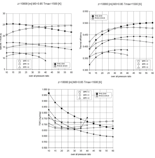
Figure 5: Specific thrust, thermal efficiency and specific fuel consumption as function of pressure ratio and BPR. [19] ... 6
Figure 6: Alternative recuperative gas turbine cycle. [24] ... 7
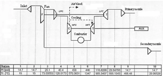
Figure 7 Engine blocks scheme and pressure and temperature computed by the code at different stations. [16] ... 8
Figure 8: Scheme of a turbofan engine with regeneration. [16] ... 8
Figure 9: Traction specific fuel consumption for a conventional turbofan and two regenerated turbofan engines at 10000 m altitude and 0.8 flight Mach number. [16] ... 8
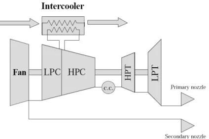
Figure 10: Engine scheme with the intercooler placed between the LPC and HPC. [16] .. 9
Figure 11: Specific thrust and thrust specific fuel consumption as function of high pressure compressor ratio. [16] ... 9
Figure 12: Schematic diagram of a high-bypass-ratio convencional turbofan. [1] ... 11
Figure 13: Reference station – turbine cooling airflows. [1] ... 11
Figure 14: CF6-80A2 engine. [33] ... 15
Figure 15: Turbojet and Turbofan Overall Pressure Ratio Trends. [11] ... 16
Figure 16: Turbojet and Turbofan Thrust-Specific Fuel Consumption Trends. [11] ... 17
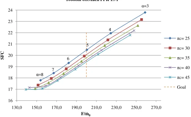
Figure 17: Specific Fuel Consumption vs Specific Thrust at cruise conditions for conventional engine ... 21
Figure 18: Specific Thrust vs Overall Pressure Ratio for a conventional engine... 22
Figure 19: Specific Fuel Consumption vs Overall Pressure Ratio for conventional engine ... 22
Figure 20: Specific Thrust vs Fan Pressure Ratio for a conventional engine... 23
Figure 21: Specific Fuel Consumption vs Fan Pressure Ratio for a conventional engine ... 23
Figure 22: Single spool with intercooler and load. [4] ... 25
Figure 23: Scheme and reference numbering of a turbofan engine with Intercooling. [Adapted by 1] ... 26
Figure 24: Reference station – turbine cooling airflows and Intercooling. [Adapted by 1] ... 26
Figure 25: Specific Fuel Consumption vs Specific Thrust at cruise conditions for an engine with intercooler. ... 27
Figure 26: Specific Thrust vs Overall Pressure Ratio for engine with intercooler. ... 27
Figure 27: Specific Fuel Consumption vs Overall Pressure Ratio for an engine with intercooler. ... 28
Figure 28: Specific Thrust vs Fan Pressure Ratio for an engine with intercooler. ... 28
Figure 29: Specific Fuel Consumption vs Fan Pressure Ratio for an engine with intercooler. ... 29
vii
Figure 30: A gas-turbine engine with regenerator. [35] ... 30
Figure 31: Thermodynamic cycle of a turbofan engine with regeneration. [35] ... 30
Figure 32: Scheme and reference numbering of a turbofan engine with regenerator. [Adapted by 1] ... 31
Figure 33: Reference station – turbine cooling airflows and regeneration. [Adapted by 1] .. 31
Figure 34: Specific Fuel Consumption vs Specific Thrust at cruise conditions for an engine with regenerator. ... 32
Figure 35: Specific Thrust vs Overall Pressure Ratio for engine with regenerator. ... 32
Figure 36: Specific Fuel Consumption vs Overall Pressure Ratio for an engine with regenerator. ... 33
Figure 37: Specific Thrust vs Fan Pressure Ratio for an engine with regenerator. ... 33
Figure 38: Specific Fuel Consumption vs Fan Pressure Ratio for an engine with regenerator. ... 34
Figure 39: Single spool with intercooler and regenerator loaded. [4] ... 35
Figure 40: Scheme and reference numbering of a turbofan engine with intercooler and regenerator.[Adapted by 1] ... 35
Figure 41: Reference station – turbine cooling airflows, intercooler and regeneration. [Adapted by 1] ... 35
Figure 42: Specific Fuel Consumption vs Specific Thrust at cruise conditions for an engine with intercooler and regenerator. ... 36
Figure 43: Specific Thrust vs Overall Pressure Ratio for engine with intercooler and regenerator. ... 37
Figure 44: Specific Fuel Consumption vs Overall Pressure Ratio for an engine with intercooler and regenerator. ... 37
Figure 45: Specific Thrust vs Fan Pressure Ratio for an engine with intercooler and regenerator. ... 38
Figure 46: Specific Fuel Consumption vs Fan Pressure Ratio for an engine with intercooler and regenerator. ... 38
Figure 47: Specific Fuel Consumption vs Specific Thrust ... 39
Figure 48: Specific Fuel Consumption vs Fan Pressure Ratio ... 40
Figure 49: Specific Thrust vs Fan Pressure Ratio ... 41
Figure 50: Specific Fuel Consumption vs Low Pressure Compressor Ratio ... 41
Figure 51: Specific Thrust vs Low Pressure Compressor Ratio ... 42
Figure 52: Specific Fuel Consumption vs Overall Pressure Ratio ... 43
Figure 53: Specific Thrust vs Overall Pressure Ratio ... 43
Figure 54: Thermal Efficiency vs Bypass Ratio ... 44
Figure 55: Thermal Efficiency vs Fan Pressure Ratio ... 44
Figure 56: Thermal Efficiency vs Low Pressure Compressor Ratio ... 45
viii
List of Tables
Table 1: Compressor characteristics as deduced by reference engine thermal cycle. [16] 7
Table 2: Station numbering. [1] ... 12
Table 3: Efficiency of components [1] ... 13
Table 4: Requirements for the engines. ... 15
Table 5: Typical F/ṁ0 and SFC values. [1] ... 18
Table 6: Main parameters for conventional engine ... 24
Table 7: Main parameters for an engine with intercooler. ... 29
Table 8: Main parameters for an engine with regenerator. ... 34
ix
Nomenclature
a - Intake b – Burner c – Compressor e – Efficiency f – Fan F/ṁ0 – Specific ThrustFPR – Fan Pressure Ratio GE – General Electric H – High
HPC – High Pressure Compressor HPT – High Pressure Turbine i – Intercooler
ICAO – International Civil Aviation Organization IRA – Intercooler Recuperated Aero Engine L – Low
LPC – Low Pressure Compressor LPT – Low Pressure Turbine LTO – Landing and Take-Off m – Mechanic
ṁ0 – Mass Flow
n – Nozzle
OPR – Overall Pressure Ratio RFP – Request For Proposal reg – Regenerator
SFC – Dimensionless Specific Fuel Consumption t – Stagnation, Turbine
TET – Turbine Entry Temperature
TSFC – Thrust Specific Fuel Consumption
Hellenic letters
α – Bypass Ratio γ – Heat Capacity Ratio
x δ – Dimensionless Pressure Ratio
ε – Cooling Mass Flow (%) η – Cycle Efficiency
ηth – Thermal Efficiency
θ – Dimensionless Temperature Ratio π – Pressure Ratio
ρ – Density
1
1. Introduction
1.1. Motivation
The environment is one thing that the Human being can´t dominate, but have the power to change! The emissions of any combustion engine are co-responsible for changes in the environment. Everyday many civil and military aircraft fly the sky and every one send to the sky tones of fuel. So, if it´s possible to reduce this fuel emission, the environment can become better and the quality of life can be improved.
The influence of climate change, air pollution and noise around airports motivated the International Civil Aviation Organization (ICAO) to promote some programs to find promising solutions for aircraft engines. Due to these requirements, civil aviation engines need to have low specific fuel consumption and high reliability, so it is very important to research new engine concepts.
The importance of the reduction of fuel consumption is mainly for two reasons: the necessity to save fuel, and the need to reduce the air pollution.
1.2. Objectives
The objectives of this thesis are to find a conventional engine, respecting the requirements imposed, and compare it with other three new configurations. These three cycles have the same base line and the main objective is to carry out if the new working cycles are viable solutions for fuel saving with reduction of specific fuel consumption.
1.3. Thesis structure
The thesis is structured in the following chapter:
• Chapter 2: Concept’ s background
In this chapter is made a short introduction to the various engine configurations. It is divided into two sections, one that shows a study related to the engine with two spools, with intercooler and regenerator. The other section is a numerical study of the main parameters of an engine with heat recovery.
• Chapter 3: Concept’s requirements
For the study of the engine are defined the requirements in this chapter. It is also show a real engine as reference. This engine is the reference basis of the requirements for the different engine configurations studied.
2 • Chapter 4: Conventional cycle
Through the requirements defined on Chapter 3, is made a design of a conventional engine and a parametric analysis, from which are obtained the values of the design parameters (conventional engine with two spools).
• Chapter 5: Novel cycle comparison
This chapter is the most important chapter because it is where is made the design of the three engine configurations. It also made a comparison between an engine with intercooler, regenerator or both, and a conventional engine. This chapter shows the difference in specific fuel consumption among the four types of engines.
• Chapter 6: Conclusion
This chapter is devoted to conclusions from the comparative study between these different engine configurations and shows which is the engine with less specific fuel consumption.
• Chapter 7: Future work
2. Concept’s background
Evolution of flight requirements demanded along time
aeronautical utilization. Emissions of gaseous pollutants have been a relevant issue to nowadays society and this is one of the key parameters to improve the existing
distance aircraft engines. In Europe and United States programs aimed at reducing CO
programs tend to be related to the ICAO Landing and Take
Figure 1: The ICAO landing and take
The effect of these emissions on air quality in the vicinity of airports became a matter of public concern like the noise problem.
This program has lead to several
in civil aviation are restricted to highly optimized turbofan engines. led to the consideration of changing the conventional engine cycle. cycles is introduced an intercool
cycle provide high thermal efficiency and low specific fuel consumption.
This novel cycle is not new! It is new for aeronautical applications but it already exists in industrial and navy applications. The
implement on aero engines because weight and size problem
weight and extra size is not a problem but in the aircraft are always prohibit A new type of engine is in development
regeneration, called IRA (Intercooler Recuperated Aero Engine). The cycle of this new engine is
Figure 2: a) IRA cycle with two heat transfer
Concept’s background
Evolution of flight requirements demanded along time new engine concept aeronautical utilization. Emissions of gaseous pollutants have been a relevant issue to
society and this is one of the key parameters to improve the existing aircraft engines. In Europe and United States there are substantia
programs aimed at reducing CO2 and NOx emissions. The goals of some of these
programs tend to be related to the ICAO Landing and Take-Off (LTO) cycle.
: The ICAO landing and take-off cycle (LTO). [25]
fect of these emissions on air quality in the vicinity of airports became a like the noise problem.
has lead to several developments. Nowadays, modern technologies in civil aviation are restricted to highly optimized turbofan engines. Research
led to the consideration of changing the conventional engine cycle. In o
an intercooler and a regenerator. This change of the conventional cycle provide high thermal efficiency and low specific fuel consumption.
This novel cycle is not new! It is new for aeronautical applications but it already navy applications. The hardware of this cycle is not ready to implement on aero engines because weight and size problems. In the ground the extra weight and extra size is not a problem but in the aircraft are always prohibit
A new type of engine is in development. It is an engine with intercool regeneration, called IRA (Intercooler Recuperated Aero Engine). The
cycle of this new engine is presented in Figure 2.
IRA cycle with two heat transfer processes and b) IRA vs Conventional
3 new engine concepts for aeronautical utilization. Emissions of gaseous pollutants have been a relevant issue to society and this is one of the key parameters to improve the existing for long are substantial research emissions. The goals of some of these
Off (LTO) cycle.
fect of these emissions on air quality in the vicinity of airports became a
modern technologies Research findings In one of the novel the conventional cycle provide high thermal efficiency and low specific fuel consumption.
This novel cycle is not new! It is new for aeronautical applications but it already e is not ready to . In the ground the extra weight and extra size is not a problem but in the aircraft are always prohibitive.
is an engine with intercooler and regeneration, called IRA (Intercooler Recuperated Aero Engine). The thermodynamic
In this cycle the intercooling
exchange with part of the bypass flow. This would increase the fuel flow so that the turbine entry temperature remains high.
so it is used a heat exchanger. This component recover
the air flow from the HPC before the combustor chamber inlet. It is important the utilization of both heat exchangers in order to increase the core specific power and keep the SFC low. The benefices proposed by this cycle are very attractive, however the heat exchanger is not yet fully
are still required.
Another modification that can be done to the conventional cycle, reduce CO2 and NOx emissions, is using only
shown the simple cycle with a re
Figure
Like the IRA cycle, the re
before the combustor chamber inlet after exit from HPC.
Several researches have been carried out on the use of a gas turbine, as shown, for example,
and recovers heat from the hot
compressed air before entering the combustor.
the fixed TET. Recuperated cycles are widely used in ground gas turbines in order to increase the thermal efficiency and so to decrease the SFC. Re
used in aero gas turbines due to their significantly high weight and size. However their introduction might have good results regarding fuel consumption and emission levels.
2.1. Literature Review
The study of turbofan engines is
of cycle: a cycle with intercooler and regeneration. The studies that have been developed until now are all related to a
refers to a type of engine
intercooling is made cooling the LPC outlet flow by with part of the bypass flow. This would increase the fuel flow so that the turbine entry temperature remains high. It is needed to reduce this increase of fuel flow, so it is used a heat exchanger. This component recovers heat from the exhaust
flow from the HPC before the combustor chamber inlet. It is important the utilization of both heat exchangers in order to increase the core specific power and keep the SFC low. The benefices proposed by this cycle are very attractive, however the heat anger is not yet fully researched and knowledge about its efficiency and behavior
Another modification that can be done to the conventional cycle, emissions, is using only the regenerator. On the
with a regenerator.
Figure 3: Simple cycle with heat-exchange. [2]
Like the IRA cycle, the regenerator, increase the combustion air before the combustor chamber inlet after exit from HPC.
Several researches have been carried out on the use of a regenerator
, for example, in ref 30. The regenerator is located in the exhaust and recovers heat from the hot exhaust gas stream in order to heat up the high pressure air before entering the combustor. With this it requires less fuel to achieve the fixed TET. Recuperated cycles are widely used in ground gas turbines in order to
iciency and so to decrease the SFC. Regenera
used in aero gas turbines due to their significantly high weight and size. However their introduction might have good results regarding fuel consumption and emission levels.
Literature Review
The study of turbofan engines is nowadays being directed to a very specific type of cycle: a cycle with intercooler and regeneration. The studies that have been developed until now are all related to an engine with three spools. The below
a bit different, with only two spools. In this type of engine
4 cooling the LPC outlet flow by heat with part of the bypass flow. This would increase the fuel flow so that the increase of fuel flow, exhaust to preheat flow from the HPC before the combustor chamber inlet. It is important the utilization of both heat exchangers in order to increase the core specific power and keep the SFC low. The benefices proposed by this cycle are very attractive, however the heat efficiency and behavior
Another modification that can be done to the conventional cycle, also in order to rator. On the Figure 3 it is
combustion air temperature
regenerator alone in a is located in the exhaust exhaust gas stream in order to heat up the high pressure this it requires less fuel to achieve the fixed TET. Recuperated cycles are widely used in ground gas turbines in order to generators are not yet used in aero gas turbines due to their significantly high weight and size. However their introduction might have good results regarding fuel consumption and emission levels.
being directed to a very specific type of cycle: a cycle with intercooler and regeneration. The studies that have been The below article different, with only two spools. In this type of engine
there are three compressors
compressor are operated by low pressure turbine. The high operated by the high pressure turbine.
R. Andriani and U. Ghezzi
ByPass Jet Engine with Intercooling and Regeneration
turbofan engine at high bypass
advantages, in terms of power increase and fuel consumption reduction, of the introduction of regeneration and
ratio. In their work, some simplifications in the engine air bleeding for auxiliary or cooling system, perfect gas fluids, no auxiliary power extracted from the turbine. T with intercooling and regeneration
in Figure 4 b).
Figure 4: a) Scheme of a turbofan engine with
This work has been done
Mach number of 0.85; TET is in one case 1300 K and in the other 1500 K; three val of bypass ratio (BPR): 3, 6 and 9; fan pressure ratio
1.70; efficiency of intercooling
maintained constant at 5%; the cycles c
component efficiencies were selected and kept constants.
The conditions were kept constants at cruise condition, being TET and BPR changed. The curves are plotted as funct
The graphics represented on turbofan engine and one in which
The results of this parametric study show that the introduction of
and regenerator only has good effects when TET and OPR are high. However if the level of TET is very high, especially at high altitude, can introduce mechanical problems to the high pressure turbine blades.
compressors but only two turbines. The fan and the
by low pressure turbine. The high-pressure compressor is by the high pressure turbine.
U. Ghezzi with the article “Performance Analysis of High
ByPass Jet Engine with Intercooling and Regeneration” [19] do a parametric study of a urbofan engine at high bypass ratio. The objective of this work is to put in evidence the advantages, in terms of power increase and fuel consumption reduction, of the
regeneration and intercooling in a turbofan engine with
some simplifications in the engine operations have been done: no air bleeding for auxiliary or cooling system, perfect gas behaviors for the working , no auxiliary power extracted from the turbine. The scheme of a turbofan engine and regeneration is shown in Figure 4 a) and the thermodynamic cycle
Scheme of a turbofan engine with intercooling and regeneration and Thermodynamic cycle. [19]
has been done considering an altitude of 10000 meters with Mach number of 0.85; TET is in one case 1300 K and in the other 1500 K; three val
pass ratio (BPR): 3, 6 and 9; fan pressure ratio was kept constant in all cases at intercooling and regeneration: 0.6; the pressure drop ha
maintained constant at 5%; the cycles computed are real and not ideal and the were selected and kept constants.
The conditions were kept constants at cruise condition, being TET and BPR changed. The curves are plotted as function of the compressor overall pressure ratio. The graphics represented on the Figure 5 present the behavior of a conventional turbofan engine and one in which intercooling and regeneration.
The results of this parametric study show that the introduction of
good effects when TET and OPR are high. However if the level of TET is very high, especially at high altitude, can introduce mechanical
the high pressure turbine blades.
5 the low pressure pressure compressor is
Performance Analysis of High
do a parametric study of a ork is to put in evidence the advantages, in terms of power increase and fuel consumption reduction, of the with high by-pass operations have been done: no rs for the working heme of a turbofan engine thermodynamic cycle
and regeneration and b)
an altitude of 10000 meters with flight Mach number of 0.85; TET is in one case 1300 K and in the other 1500 K; three values as kept constant in all cases at he pressure drop has been omputed are real and not ideal and the
The conditions were kept constants at cruise condition, being TET and BPR ion of the compressor overall pressure ratio. present the behavior of a conventional
The results of this parametric study show that the introduction of the intercooler good effects when TET and OPR are high. However if the level of TET is very high, especially at high altitude, can introduce mechanical
Figure 5: Specific thrust, thermal efficiency and specific fuel consumption as function of pressure
Another study using
“Analysis of the recuperative gas turbine cycle with a
turbines” [24]. A recuperative gas high-pressure turbine and a low
with the simple cycle and conventional recuperative cycle in detail.
The analysis show that for the recuperative gas turbine cycle with
located between turbines, the efficiency of the ideal alternative recuperative cycle can be higher than the ideal conventional recuperative gas turbine cycle with the same temperature ratio, but the specific work of former is much
maximum optimum efficiency of
lower than that of a conventional recuperative cycle, and the optimum pressure ratio for the higher efficiency of an
conventional recuperative cycle. The alternative recuperated cycle does not exhibit the highest efficiency and thus the alternative cycle with a re
still requires further improvements
: Specific thrust, thermal efficiency and specific fuel consumption as function of pressure ratio and BPR. [19]
Another study using regenerator was done by Cai Ruixian and Jiang Lixia
Analysis of the recuperative gas turbine cycle with a regenerator located between
A recuperative gas turbine cycle with a regenerator located between a bine and a low-pressure turbine. This article analyzed and compared with the simple cycle and conventional recuperative cycle in detail.
The analysis show that for the recuperative gas turbine cycle with
located between turbines, the efficiency of the ideal alternative recuperative cycle can ideal conventional recuperative gas turbine cycle with the same temperature ratio, but the specific work of former is much smaller than the latter. The maximum optimum efficiency of the practical alternative recuperative cycle is always conventional recuperative cycle, and the optimum pressure ratio for
an alternative recuperative cycle is always higher than that of conventional recuperative cycle. The alternative recuperated cycle does not exhibit the
t efficiency and thus the alternative cycle with a regenerator between the turbines mprovements to become more attractive.
6
: Specific thrust, thermal efficiency and specific fuel consumption as function of pressure
was done by Cai Ruixian and Jiang Lixia,
located between
located between a analyzed and compared
The analysis show that for the recuperative gas turbine cycle with regenerator located between turbines, the efficiency of the ideal alternative recuperative cycle can ideal conventional recuperative gas turbine cycle with the same than the latter. The practical alternative recuperative cycle is always conventional recuperative cycle, and the optimum pressure ratio for alternative recuperative cycle is always higher than that of a conventional recuperative cycle. The alternative recuperated cycle does not exhibit the between the turbines
Figure 6
2.2. Relevant Studies
R. Andriani and U. Ghezzi with the article “
Performances of Gas Turbine Engines With Heat Recovery
analysis of the performance of gas turb turbofan engine with the characteristics
Table 1: Compressor characteristics as deduced by reference engine thermal cycle.
Fan LPC HPC
In Figure 7 is reported the engine scheme that has been considered for the calculations and the values of pressure and temperature at each station as they have been computed by the numerical code.
Once tested the code and seen that the resul
given data, the code was used to simulate the behaviors of the engine in different conditions. The heat exchanger is added recovering heat from the exhaust and preheating air from the compressor as shown in Figure 8. The o
the engines are: altitude of 10000 meters and flight Mach number of 0.8.
“The conventional case is the marked as R=0 while the two regenerative cases are respectively R=0.5 and R=0.7, where R is the efficiency of regeneration of the exchanger.”
6: Alternative recuperative gas turbine cycle. [24]
ies
Andriani and U. Ghezzi with the article “Numerical Analysis of Main
Performances of Gas Turbine Engines With Heat Recovery” [16] made analysis of the performance of gas turbine engines with heat recovery.
characteristics shown in the Table 1 was studied
Compressor characteristics as deduced by reference engine thermal cycle.
N. stages Pressure ratio Polytropic efficiency
1 1.71 0.831
4 1.61 0.868
11 11.34 0.872
is reported the engine scheme that has been considered for the calculations and the values of pressure and temperature at each station as they have been computed by the numerical code.
Once tested the code and seen that the results are in good agreement with the given data, the code was used to simulate the behaviors of the engine in different conditions. The heat exchanger is added recovering heat from the exhaust and preheating air from the compressor as shown in Figure 8. The operating
altitude of 10000 meters and flight Mach number of 0.8.
“The conventional case is the marked as R=0 while the two regenerative cases are respectively R=0.5 and R=0.7, where R is the efficiency of regeneration of the
7
Numerical Analysis of Main
ade a numerical ine engines with heat recovery. A high bypass
studied.
Compressor characteristics as deduced by reference engine thermal cycle. [16]
Polytropic efficiency
0.831 0.868 0.872
is reported the engine scheme that has been considered for the calculations and the values of pressure and temperature at each station as they have been
ts are in good agreement with the given data, the code was used to simulate the behaviors of the engine in different conditions. The heat exchanger is added recovering heat from the exhaust and perating conditions of altitude of 10000 meters and flight Mach number of 0.8.
“The conventional case is the marked as R=0 while the two regenerative cases are respectively R=0.5 and R=0.7, where R is the efficiency of regeneration of the heat
Figure 7 Engine blocks scheme and pressure and temperature computed by the code at different
Figure 8: Scheme of a turbofan engine with regeneration.
Figure 9: Traction specific fuel consumption for a conventional turbofan and two regenerated turbofan engines at 10000 m altitude and 0.8 flight Mach number.
Engine blocks scheme and pressure and temperature computed by the code at different stations. [16]
: Scheme of a turbofan engine with regeneration. [16]
fuel consumption for a conventional turbofan and two regenerated turbofan engines at 10000 m altitude and 0.8 flight Mach number.
8
Engine blocks scheme and pressure and temperature computed by the code at different
fuel consumption for a conventional turbofan and two regenerated turbofan engines at 10000 m altitude and 0.8 flight Mach number. [16]
The recuperated engine shows a reduction in performance at the same time.
performance by the use of output power at the same time.
Figure 10: Engine scheme with the intercooler placed between the LPC and HPC
In the conventional engine is added an intercooler as shown
the compressor absorbs less power, it becomes available in the nozzle a greater enthalpy drop for thrust.” [16].
“The cooling fluid is
pressure drop of 3% and an efficiency of 90%, defined as the ratio between the actual amount of heat transferred from working fluid to cooling air and the
could be transferred in the same operating conditions.”
The behavior of specific thrust and specific fuel consumption in the case of turbofan engine with intercooling
Figure 11: Specific thrust and thrust specific fuel consumption as function of high pressure
The recuperated engine shows a reduction in TSFC, but also a reduction in performance at the same time. Thus, Andriani and Ghezzi, recommend improving the of an intercooler. The TSFC is reduced with an increase in output power at the same time.
: Engine scheme with the intercooler placed between the LPC and HPC
In the conventional engine is added an intercooler as shown in Figure
the compressor absorbs less power, it becomes available in the nozzle a greater enthalpy
“The cooling fluid is external air. Through the intercooler we have considered a pressure drop of 3% and an efficiency of 90%, defined as the ratio between the actual amount of heat transferred from working fluid to cooling air and the
could be transferred in the same operating conditions.” [16].
of specific thrust and specific fuel consumption in the case of intercooling is depicted in the Figure 11.
Specific thrust and thrust specific fuel consumption as function of high pressure compressor ratio. [16]
9 SFC, but also a reduction in recommend improving the SFC is reduced with an increase in
: Engine scheme with the intercooler placed between the LPC and HPC. [16]
Figure 10 “Since the compressor absorbs less power, it becomes available in the nozzle a greater enthalpy
air. Through the intercooler we have considered a pressure drop of 3% and an efficiency of 90%, defined as the ratio between the actual amount of heat transferred from working fluid to cooling air and the maximum that
of specific thrust and specific fuel consumption in the case of
10
2.3. Conclusions
With the results presented, can be concluded that the use of the regenerator or its combination with an intercooler, result in a fuel consumption reduction. The approach used to research these novel cycles, is to take values of reference and compare performance results, such as, specific consumption, thermal efficiency and specific thrust. In this thesis, the procedure to obtain the results is a little different. The aim is not to compare results with the values assumed initially, but to obtain reference values such as, Bypass Ratio, OPR, FPR, etc., for each type of configuration. Thus the path taken in this thesis is to perform the parametric calculations for the same specific thrust and flight altitude to obtain the different reference values for each of the different cycles.
3. Concept’s requirements
At the beginning of any study is necessary to know the order to guarantee that the
in addition to the simplifying
nomenclature of the engine, according to
the objectives of an aircraft/engine system is needed a requireme Request For Proposal (RFP). Thus it is shown in this
study of engines with regenerator
3.1. Station Numbering
The station numbering is important to engine. The Figure 12 show
blocks diagram of components
Figure 12: Schematic diagram of a high
Figure 13
Concept’s requirements
At the beginning of any study is necessary to know theoretical theoretical study is very close to the real one
simplifying assumptions is also referred the scheme and the engine, according to the Aerospace Recommend Practice.
the objectives of an aircraft/engine system is needed a requirements document such as a or Proposal (RFP). Thus it is shown in this section the requirements for the
generator or intercooled recuperative engines.
umbering
The station numbering is important to identify the different location
shows the generalized conventional engine and Figure 13 the blocks diagram of components.
Schematic diagram of a high-bypass-ratio convencional turbofan
13: Reference station – turbine cooling airflows. [1]
11 oretical limitations in one. In this section, assumptions is also referred the scheme and the Aerospace Recommend Practice. To know nts document such as a the requirements for the
the different locations in the and Figure 13 the
12 The station numbering should be made in accordance with Aerospace Recommend Practice, as presented in Table 2.
Table 2: Station numbering. [1]
Station Location
0 Far upstream or freestream 1 Inlet or diffuser entry
2 Inlet or diffuser entry, fan entry 13 Fan exit
2.5 Low-pressure compressor exit High-pressure compressor entry 3 High-pressure compressor exit
4
Burner entry Nozzle vanes entry
Modeled coolant mixer 1 entry High-pressure turbine entry for πtH
definition
4.1
Nozzle vanes exit Coolant mixer 1 exit
High-pressure turbine entry for πtH
definition
4.4 High-pressure turbine exit Modeled coolant mixer entry
4.5 Coolant mixer 2 exit Low-pressure turbine entry 5 Low-pressure turbine exit 7 Core exhaust nozzle entry 9 Core exhaust nozzle exit 17 Bypass exhaust nozzle entry 19 Bypass exhaust nozzle exit
The ratio of total (isentropic stagnation) pressures π and total (adiabatic stagnation) temperatures τ are the following,
i component entering pressure total i component leaving pressure total i = π i component entering e temperatur total i component leaving e temperatur total i = τ
13
3.2. Assumptions
Before proceeding with the analysis, the assumptions to be employed in this thesis are summarized as follows:
- The flow is steady;
- The flow is one-dimensional at the entry and exit of each component and at each axial station;
- The fluid behaves as a perfect gas with constant molecular weight across the diffuser, fan, compressor, turbine, nozzle, and connecting ducts;
- Calorically perfect gas cp and γ are assigned one set of values from station 0 through stations 3.1 and 19 (denoted as cpc=1005 J/kgK and γc=1.4), a second
set of values from station 4 through 9 (denoted as cpt=1148 J/kgK and
γt=1.33);
- Engine Operation Condition: Standard day;
- The total pressure ratio of the diffuser or inlet, the nozzles and the burner were kept constant:
πd = 0.99
πnf= 0.99
πb= 0.96
- The fan and low-pressure compressor are driven by the low-pressure turbine, but can’t provide mechanical power for accessories, PTOL=0;
- The high-pressure compressor receives air directly from the low-pressure compressor and is driven by the high-pressure turbine, but can’t provide mechanical power for accessories, PTOH=0;
- Fuel heating was kept constant: hPR = 4.28x10⁷ J/kg
- Percent of cooling mass flow air, removed between stations 3 and 3.1, and is given by [1]: 4 1 2 t4 1 2 t4 1400 for T máx>1400K 8000 0 for T máx<1400K t máx T
ε
ε
ε
ε
− = = = =- No air bleed for auxiliary system;
- The flow in the bypass duct (from station 13 to 19) is isentropic;
- The effect of cooling on turbine efficiency is accounted for by a reduction of etH due to ṁcool 1 and ṁcool 2;
- The turbine entry temperature was kept constant: TET = 1500K; - The efficiencies of components used are presented in Table 3.
Table 3: Efficiency of components [1]
Component Value
Intake efficiency (ea) 0.99
Fan polytropic efficiency (ef) 0.89
14 High pressure compressor polytropic efficiency (ecH) 0.9
Burner efficiency (eb) 0.995
High pressure turbine polytropic efficiency (etH) 0.89 Low pressure turbine polytropic efficiency (etL) 0.91
Primary nozzle adiabatic efficiency (enf) 0.9
Secondary nozzle adiabatic efficiency (en) 0.9
Mechanical efficiency (em) 0.995
Intercooler efficiency (ei)[19] 0.6
Regenerator efficiency (ereg) [19] 0.6
- The total pressure ratio of Intercooler and Regenerator: πint = πreg=0.95 (drop = 5%)
- The regenerator leads to a decrease of thrust in the hot nozzle (based in Ref. 27):
πNzreg=0.95 (drop = 5%)
3.3. Engine requirements
When designing an aircraft, it is necessary to start with its requirements. These requirements are written on a document, commonly called RFP. This document has all the descriptions of the desired aircraft performance. In this thesis does not exist the RFP and so, to perform the parametric calculations, one must have some base values for the requirements. These requirements were based on an engine with the characteristics considered as close to the one to be studied in this thesis (CF6-80A2). The CF6-80A2 engine (see Fig. 14) is an engine build by GE and used on Boeing 767-200/-200ER/-300, having the following characteristics [34]:
Physical Information
- Fan/Compressor Stages: 1F/3LPC/14HPC
- Low-Pressure Turbine/High-Pressure Turbine Stages: 4/2 - Fan Diameter (Inches): 86,4 - Length (Inches): 167
- Dry Weight (Lb.): 8.760 – 8.776
- Airflow static (lb/s): 1460
Power Specifications
- Specific Fuel Consumption at Sea Level: 0,355 – 0,357
- Max. Power at Sea Level (Lb.): 50.000
- Specific Fuel Consumption at Cruise: 0,623
- Max. Power Cruise (Lb.): 11.000 - Overall Pressure ratio at Maximum
Power: 27,3 – 28,4 - Bypass Ratio: 4,59 – 4,66 - Cruise Speed(M): 0,8 - Cruise Altitude (ft): 35.000
With this reference engine (Conventional, Intercooled, Table 4. Table Height [m] Thrust [kN] Mass flow [ Mach TET Max
Figure 14: CF6-80A2 engine. [33]
With this reference engine, the requirements for the engine to study in this thesis (Conventional, Intercooled, Regenerative and Intercooled Recuperative)
Table 4: Requirements for the engines.
Sea Level Cruise
Height [m] 0 10668 Thrust [kN] 250 50 Mass flow [kg/s] 650 - Mach - 0,80 TET Max [K] 1500 1500 15 study in this thesis Regenerative and Intercooled Recuperative) are the show in
16
4. Conventional cycle
In this chapter is shown the conventional cycle and the calculations and graphs needed to choose the design point. The choice of the design point and the performance calculations were obtained with using Microsoft Office Excel 2007 running on a personal computer.
4.1. Conventional engine theory
Modern conventional turbofan engines can be categorized according to their application. At this point it is important to manifest the changes of variables used, corresponding to the two or three shaft configurations. With three shafts, these engines are used for long/medium-haul flights where the thrust class is about 40,000 – 100,000lbs. In the short/medium haul flights the engines are of moderate thrust class, 8,000-40,000lbs thrust, being normally used two shafts with moderate values of Overall Pressure Ratio, Turbine Entry Temperature and Bypass Ratio.
The High OPR contributes to high engine efficiency and, in turn, low SFC. However, raising the engine OPR results in heavier and more costly engines because it normally requires additional compressor or fan stages and larger turbines. In the Figure 15 is shown the steady and rapid increase in OPR for turbojets and turbofans over the past five decades. The smaller core engines, normally have lower OPRs.
Figure 15: Turbojet and Turbofan Overall Pressure Ratio Trends. [11]
The SFC is often referred to as the thrust specific fuel consumption (TSFC) and is defined as the ratio of the fuel mass flow rate to the thrust. In Figure 16 can be verified the advantage in the thrust SFC offered by turbofans when compared with turbojets. The very low SFC engines indicated at the bottom of the Figure are all high BPR turbofans.
17
Figure 16: Turbojet and Turbofan Thrust-Specific Fuel Consumption Trends. [11]
Two spool engines are generally lighter and with lower manufacturing costs due to its relative simplicity. If the SFC decreases, the weight of the aircraft decreases too because the fuel necessary to do a haul is less.
The conventional engine studied in this thesis is an engine with two spools. The high pressure turbine transfers its movement to the high-pressure compressor and the low pressure turbine transfers to the low pressure compressor and the fan.
4.2. Engine Selection
The object of a parametric cycle analysis is to obtain estimates of the performance parameters (primarily specific thrust and thrust specific fuel consumption), based on the design limitations: flight conditions (the ambient pressure, temperature, and Mach number) and design choices (such as compressor pressure ratio, fan pressure ratio, bypass ratio, and theta break). The calculation of performance parameters are based on the method presented by Jack D. Mattingly and David T. Pratt of the University of Washington and William H. Heiser of the U.S. Air Force Academy in Ref 1.The initial conditions for the iterative calculations were the ones presented in Table 5.
18
Table 5: Typical F/ṁ0 and SFC values. [1]
4.2.1.
Engine Calculations
To determine the primary measures of the engine's overall performance it is necessary to now the thrust. For a turbofan engine with separate exhausts streams it is given by:
(
9 19 19 0 0)
9(
9 0)
19(
19 0)
F= mVɺ +m Vɺ −m Vɺ +A P −P +A P −P (1)
which can be rearranged into its nondimensional form, thrust per unit mass flow of captured airflow (F/ṁ0) or specific thrust, form as:
(
)
(
)
(
)
(
)
(
)
(
)
(
)
9 19 0 0 0 0 0 9 9 9 0 0 0 0 0 9 0 0 0 19 19 0 19 0 0 1 1 1 1 1 1 1 1 1 V V f M a a P P R T T F f m a R V a P P T T V aα
β
α
α
α
β
α
γ
α
γ
+ + − + − + + − = + + + − + + − + ɺ (2)Like specific thrust, dimensionless thrust specific fuel consumption (SFC) is a performance parameter of primary interest and is obtain by:
19 0 0 f S F m = ɺ (3)
The independent design variables considered for this engine are the fan pressure ratio (πf), the overall cycle pressure ratio (πc), and the bypass ratio (α). The pressure ratio
across the high-pressure compressor is obtained from:
cH c cL
π
=π π
(4)The temperature ratios across the fan (τf), the low-pressure compressor (τcL), and the
high-pressure compressor (τcH) are related to their pressure ratios by equations 5, 6 and
7, respectively. 13 2 t f t T T τ = (5) 2.5 2 t cL t T T τ = (6) 3 2.5 t cL t T T τ = (7)
The temperature ratios across the high-pressure turbine (τtH) and low-pressure turbine
(τtL) are obtained from power balances of the high- and low-pressure spools resulting in
equations 8 and 9.
(
) (
)
(
)(
)
{
1 2 1}
1 1 1 1 1 r cL cH TOH mPH tH mH r cL cH C f λ λτ τ
τ
α
η
τ
η τ
β ε
ε
ε τ τ τ
τ
− + + = − − − − + + (8)(
)
(
)
{
}
(
)
(
)(
) (
)
{
1 2 1 2}
1 1 1 1 1 1 r cL f TOL mPL tL mH tH tH r cL cH C f λ λτ
τ
α τ
α
η
τ
η τ τ
β ε
ε
ε
ε τ
τ τ τ
τ
− + − + + = − − − − + + + (9)The temperature ratios across the two cooling air mixing processes (τml and τm2) are
given by equations 10 and 11.
(
)(
)
(
)(
)
1 2 1 1 1 2 1 1 1 1 1 r cL cH m f f λ β ε ε ε τ τ τ τ τ β ε ε ε − − − + + = − − − + + (10)20
(
)(
)
{
(
)
}
(
)(
)
1 2 1 2 1 2 1 2 1 2 1 1 1 1 r cL cH m tH m f f λβ ε
ε
ε
ε τ τ τ
τ τ τ
τ
β ε
ε
ε
ε
− − − + + + = − − − + + + (11)The pressure ratios across the high-pressure turbine (πtH) and low-pressure turbine (πtL)
are related to their respective temperature ratio and polytropic efficiency by equations 12 and 13. 1 r 4.4 r 4.1 P P tH e t tH t π = (12) 1 r 5 r 4.5 P P tL e t tL t π = (13)
The fuel-air ratio (f) is given by equation 14.
0 r cL cH PR b f h h λ λ τ τ τ τ η τ − = − (14)
Thus, the only unknowns for the obtention of the specific thrust (see equation 2), are the pressure ratios, P0/P9 and P0/P19. This turbofan engine is modeled as having fixed convergent nozzles for both the core and bypass air streams. Thus, the exit pressure is equal to the ambient pressure for unchoked nozzle operation and the exit pressure is greater than the ambient pressure when the nozzle flow is choked.
As the mass flow rate, at engine entry, changes with the Mach number, the temperature, and the pressure, the "corrected mass flow rate” used in this analysis is defined as:
0 cruise SL cruise cruise
mɺ =mɺ =mɺ
δ
θ
(15)The dimensionless pressure and temperature are represented by δ and θ, respectively. This corrected mass flow rate has to be calculated because, in the requirements, the mass flow it is given at sea level.
4.2.2.
Engine Analysis
Through the requirements described in section 3.3 of this thesis was possible to obtain different graphics in order to choose the values of the parameters that lead to the higher engine performance. These graphs were obtained by iterative calculations, varying the parameters to obtain the best values for choosing the on-design point of an engine. The Figures 17-21 indicate how were obtained the parameters for the on-design point of the engine project.
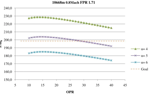
21 Through Figure 17 can be obtained an estimate of the values of bypass at the cruise altitude. We can also verify that the range of bypass values will be between 4 and 6. In what concerns the values of OPR that best suit the requirements, Figure 18 shows the variation of OPR for different bypass values.
Figure 17: Specific Fuel Consumption vs Specific Thrust at cruise conditions for conventional engine
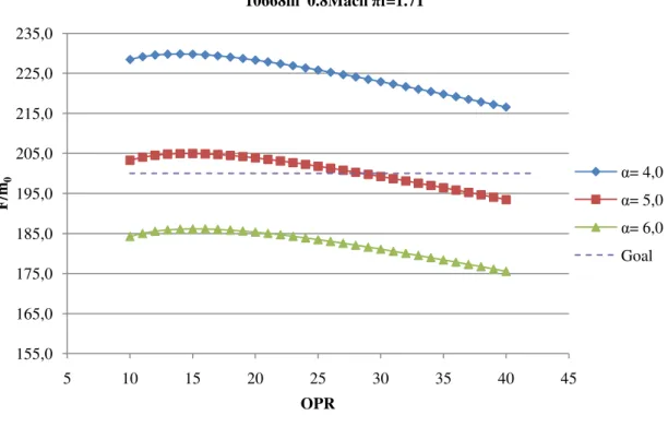
From Figure 18 can be seen that to obtain the value of 200 for the specific thrust, the value for OPR will have to be 26. This for a bypass value equal to 5 or lower because if the bypass value is greater than 5 for any value of the OPR, the requirement will never be reached. If it is smaller than five it puts itself in commitment the increase of fuel consumption as shown in the Figure 19. This graph shows the variation of specific fuel consumption with the OPR in the range of bypass values previously defined.
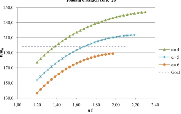
The choice of the fan pressure ratio, FPR, is made through a graph that shows the influence of the specific thrust with the changes in the FPR. Figure 20 shows this variation for the altitude and cruise speed and for an OPR equal to 26.
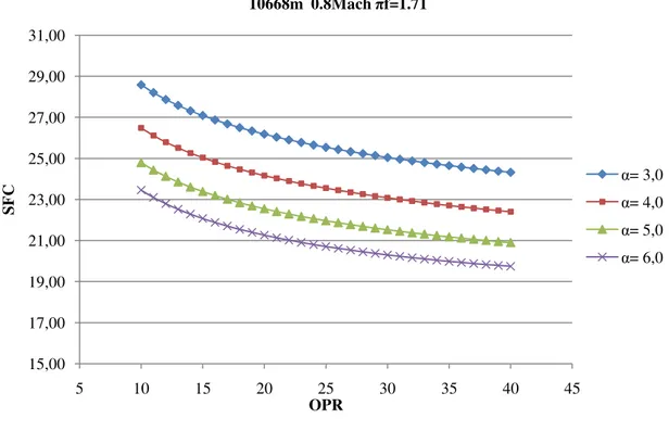
As well as in the choice of the best OPR, the value for the FPR is 1.71. This value is chosen considering the desired requirement as the lowest fuel consumption possible for a fixed bypass of 5. Figure 21 shows the effect of the fan pressure ratio in the specific fuel consumption.
These Figures shows that the consumption decreases with the increase of the FPR and the bypass. The value of FPR is optimized for the specific thrust that was required previously. 16 17 18 19 20 21 22 23 24 130,0 150,0 170,0 190,0 210,0 230,0 250,0 270,0 S F C F/ṁ0 10668m 0.8Mach FPR 1.71 πc= 25 πc= 30 πc= 35 πc= 40 πc= 45 Goal α=3 α=8 4 5 6 7
22
Figure 18: Specific Thrust vs Overall Pressure Ratio for a conventional engine
Figure 19: Specific Fuel Consumption vs Overall Pressure Ratio for conventional engine 150,0 160,0 170,0 180,0 190,0 200,0 210,0 220,0 230,0 240,0 5 10 15 20 25 30 35 40 45 F / ṁ 0 OPR 10668m 0.8MachFPR 1.71 α= 4 α= 5 α= 6 Goal 17 19 21 23 25 27 5 10 15 20 25 30 35 40 45 S F C OPR 10668m 0.8Mach FPR 1.71 α= 3 α= 4 α= 5 α= 6
23
Figure 20: Specific Thrust vs Fan Pressure Ratio for a conventional engine
Figure 21: Specific Fuel Consumption vs Fan Pressure Ratio for a conventional engine 130,0 150,0 170,0 190,0 210,0 230,0 250,0 1,00 1,20 1,40 1,60 1,80 2,00 2,20 2,40 F / ṁ 0 πf 10668m 0.8Mach OPR 26 α= 4 α= 5 α= 6 Goal 18 20 22 24 26 28 30 1,00 1,20 1,40 1,60 1,80 2,00 2,20 2,40 S F C πf 10668m 0.8Mach OPR26 α= 3 α= 4 α= 5 α= 6
24
4.3. Results
The values obtained are not fully optimized because this would require a complete study of the engine performance, considering several altitudes and turbine inlet temperatures, and thus it would be out of the main objective. The main purpose of this study is to compare several configurations in the same working conditions and so, these results are an approximation of the actual choice of a conventional engine.
The estimated values of the performance parameters for a conventional engine, with two spools, and a specific thrust of 200, at a cruise altitude of 10668m and a Mach 0.8 are shown in the Table 6.
Table 6: Main parameters for conventional engine
Main Parameters Value Overall pressure ratio 26
Fan pressure ratio 1.71 Bypass ratio 5
5. Novel cycles comparison
The objective of this chapter is to
the parameters of performance for three configurations. One with Intercooler, another with regeneration and the last with
engine). The requirements
chapter 3. In the last section is compare conventional engine obtained
5.1. Engine with Intercooling
Intercooling consists in stage (LPC) to the inlet of the compression ratio, the work
on the conventional adiabatic case. Since the compressor
available in the nozzle a greater enthalpy drop for thrust. This practice is not new, and many ground power systems adopt i
scheme and thermodynamic
Figure
5.1.1.
Configuration
The cycle with intercooler
located between the low pressure compressor and the high pressure compressor. Figure shows also the station numbering used
In Figure 23 is shown the location of the intercooler. This component is located between the compressors
conventional engine, the nomenclature used in this engine
the intercooler. Thus it is necessary to introduce a new location for the parametric calculations (2.1). It can be seen in
flow between compressors. The cooling system is not affected by the introduction of this component
comparison
objective of this chapter is to show different types of cycles and calculate the parameters of performance for three configurations. One with Intercooler, another with regeneration and the last with these two components (intercooled recuperative
for these three different engines are the ones considered he last section is compares these three configuration
ed in chapter 4.
Engine with Intercooling
consists in cooling down the air temperature between the exit of one to the inlet of the following (HPC). This way, once fixed the global compression ratio, the work needed to raise the air pressure is less than the one needed
the conventional adiabatic case. Since the compressor spends less power, it
available in the nozzle a greater enthalpy drop for thrust. This practice is not new, and ground power systems adopt it to increase the output power.
scheme and thermodynamic cycle are presented in Fig. 22.
re 22: Single spool with intercooler and load. [4]
onfiguration
The cycle with intercooler is shown in Figure 23 and 24. The intercooler is located between the low pressure compressor and the high pressure compressor.
the station numbering used in the calculations.
23 is shown the location of the intercooler. This component is located and makes the cooling between them. Compared to the omenclature used in this engine only varies at the entrance of the intercooler. Thus it is necessary to introduce a new location for the parametric calculations (2.1). It can be seen in Figure 24 that the intercooler only interferes with the ompressors. The cooling system is not affected by the introduction of
25 show different types of cycles and calculate the parameters of performance for three configurations. One with Intercooler, another intercooled recuperative different engines are the ones considered in three configurations with the
een the exit of one his way, once fixed the global than the one needed less power, it becomes available in the nozzle a greater enthalpy drop for thrust. This practice is not new, and t to increase the output power. The hardware
he intercooler is located between the low pressure compressor and the high pressure compressor. This
23 is shown the location of the intercooler. This component is located and makes the cooling between them. Compared to the only varies at the entrance of the intercooler. Thus it is necessary to introduce a new location for the parametric 24 that the intercooler only interferes with the ompressors. The cooling system is not affected by the introduction of
Figure 23: Scheme and reference numbering of a turbofan engine with
Figure 24: Reference station
5.1.2.
Calculation method
The calculation method used it is conventional engine. Nevertheless, there is a pressure compressor, there is a
high pressure compressor. Through the intercooler 5% and the efficiency as 60%.
lower ones that occurred in the initial studies of these aero engines reality higher, that improves
5.1.3.
Analysis and comments
The Figure 25-29 shows, principal parameters of an
are the same, as the conventional engine, 5 and 1.71 respectively. The difference in this engine with intercooler, is that to respect the requi
have to be higher than the one used in the conventional engine. This happens because
Scheme and reference numbering of a turbofan engine with Intercooling
: Reference station – turbine cooling airflows and Intercooling.
Calculation method
The calculation method used it is similar to the one used in the calculation of the Nevertheless, there is a difference, when the flow
, there is a decrease on the temperature. After that, the
Through the intercooler, the pressure drop was considered 60%. These values were considered, because
in the initial studies of these aero engines. If these improves overall performance of the engine.
sis and comments
29 shows, in an analogous way to the conventional engine the engine with intercooler. The bypass and fan pressure ratios are the same, as the conventional engine, 5 and 1.71 respectively. The difference in this engine with intercooler, is that to respect the requirements, the overall pressure ratio have to be higher than the one used in the conventional engine. This happens because
26
Intercooling. [Adapted by 1]
[Adapted by 1]
similar to the one used in the calculation of the difference, when the flow exits the low the air enters the the pressure drop was considered as because they were the . If these values are in
e conventional engine the engine with intercooler. The bypass and fan pressure ratios are the same, as the conventional engine, 5 and 1.71 respectively. The difference in this rements, the overall pressure ratio have to be higher than the one used in the conventional engine. This happens because
27 the compressor work reduces due to the intercooler.So, the value of the overall pressure ratio is 29.
Figure 25: Specific Fuel Consumption vs Specific Thrust at cruise conditions for an engine with intercooler.
Figure 26: Specific Thrust vs Overall Pressure Ratio for engine with intercooler.
19 20 21 22 23 24 25 26 27 130,0 150,0 170,0 190,0 210,0 230,0 250,0 270,0 S F C F/ṁ0 10668m 0.8Mach πf=1.71 πc= 20 πc= 25 πc= 30 πc= 35 Goal 5 6 7 8 α=3 4 α=9 155,0 165,0 175,0 185,0 195,0 205,0 215,0 225,0 235,0 5 10 15 20 25 30 35 40 45 F / ṁ 0 OPR 10668m 0.8Mach πf=1.71 α= 4,0 α= 5,0 α= 6,0 Goal
28
Figure 27: Specific Fuel Consumption vs Overall Pressure Ratio for an engine with intercooler.
Figure 28: Specific Thrust vs Fan Pressure Ratio for an engine with intercooler. 15,00 17,00 19,00 21,00 23,00 25,00 27,00 29,00 31,00 5 10 15 20 25 30 35 40 45 S F C OPR 10668m 0.8Mach πf=1.71 α= 3,0 α= 4,0 α= 5,0 α= 6,0 130,0 150,0 170,0 190,0 210,0 230,0 250,0 1,00 1,20 1,40 1,60 1,80 2,00 2,20 2,40 F / ṁ 0 πf 10668m 0.8Mach OPR 29 α= 4,0 α= 5,0 α= 6,0 Goal
29
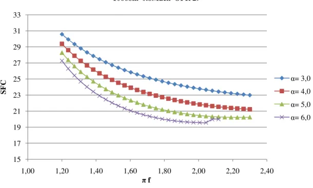
Figure 29: Specific Fuel Consumption vs Fan Pressure Ratio for an engine with intercooler.
The Table 7 shows the main parameters for an engine only with intercooling.
Table 7: Main parameters for an engine with intercooler.
Main Parameters Value
Overall pressure ratio 29 Fan pressure ratio 1.71
Bypass ratio 5
5.2. Engine with Regeneration
In gas-turbine engines, the temperature of the exhaust gases leaving the turbine is often considerably higher than the temperature of the air leaving the compressor. Therefore, the high pressure air leaving the compressor can be heated by transferring heat to it from the hot exhaust gases in a counter-flow heat exchanger, which is also known as a regenerator. The cycle with that configuration in shown Figure 30, where can be seen the hardware needed to transfer heat from the exhaust gases leaving the turbine to the air flow leaving the compressor. Using the regenerator the fuel needed to raise the temperature, of the air leaving the compressor decreases. The thermal efficiency of this cycle increases as a result of regeneration, since less fuel is used for the same work output. In Figure 31 is presented the ideal thermodynamic cycle for the same gas turbine with regeneration.
15 17 19 21 23 25 27 29 31 33 1,00 1,20 1,40 1,60 1,80 2,00 2,20 2,40 S F C πf 10668m 0.8Mach OPR 29 α= 3,0 α= 4,0 α= 5,0 α= 6,0
![Figure 32: Scheme and reference numbering of a turbofan engine with regenerator. [Adapted by 1]](https://thumb-eu.123doks.com/thumbv2/123dok_br/18207064.876424/42.892.147.709.120.355/figure-scheme-reference-numbering-turbofan-engine-regenerator-adapted.webp)
