Structural Analysis of Historic Construction – D’Ayala & Fodde (eds) © 2008 Taylor & Francis Group, London, ISBN 978-0-415-46872-5
Analysis and diagnosis of timber structures in Porto historical centre
T. Ilharco, J.M. Guedes & A. ArêdeFaculty of Engineering, University of Porto, Porto, Portugal E. Paupério
Construction Institute, Faculty of Engineering, University of Porto, Porto, Portugal A.G. Costa
Autonomous Section of Civil Engineering, University of Aveiro, Aveiro, Portugal
ABSTRACT: The historical centre of Porto was considered in 1996 UNESCO World Heritage due to the outstanding universal value of the site, with urban fabric and historic buildings that bear remarkable testimony to the development over the past thousand years of an important European city”. In order to contribute to the maintenance of this remarkable set of buildings, with historical, architectural, constructive and heritage value, in opposition to the continuous built heritage degradation process and the population dislocation from the centre to the surroundings, NCREP –FEUP have been participating in many rehabilitation projects, analyzing the conservation state of building structural elements (stone masonry walls and timber floors and roofs). The focus of the present paper is given to the evaluation of the physical state of timber structural elements, namely to the various instruments used on the Analysis and Diagnosis phases, in particular to the non destructive (NDT), medium-destructive (MDT) and, in a certain context, destructive testing techniques.
1 INTRODUCTION
The inscription of the cistorical centre of Porto as UNESCO World Heritage was based on the cultural criterion “(iv)”, considering that the site is of “out-standing universal value as the urban fabric and its many historic buildings bear remarkable testimony to the development over the past thousand years of an important European city”, Figure 1. Hence, the choice of UNESCO was based on the knowl-edge that a remarkable set of buildings with indi-vidual and unrepeatable characteristics transmits out-standing testimonies about the city and its ancestor history.
Nonetheless, all the old part of the city presents a serious problem of degradation of its built heritage, with a large number of buildings demanding fast inter-vention and rehabilitation measures, together with the social problems and the dislocation of the population from the centre to the surroundings, Figure 2.
Therefore, it is fundamental to endeavour efforts to preserve this remarkable set of buildings (adapt-ing them to today comfort demands), with harmonious architectonical solutions and decorative elements, fol-lowing particular constructive and typological sys-tems, avoiding its continuous physical degradation and abandonment.
Figure 1. View of Porto historical centre (Google Earth).
Figure 2. Porto Hhistorical city centre.
So, let’s intervene, but then a fundamental question arises: should it be at any cost? In fact, the urgent need for the interventions can’t lead to neglectful decisions. On the contrary, the interventions must be based on a
careful analysis made by experts from different areas, involving not only structural and architectural matters, but also historical and social issues.
With the objective of promoting sustainable rehabilitation interventions, following ICOMOS (International Council on Monuments and Sites) rec-ommendations, NCREP (Nucleus for the Conser-vation and Rehabilitation of Buildings and Built Heritage, a team within FEUP – Faculty of Engineer-ing of the University of Porto) have been participatEngineer-ing in many rehabilitation projects, doing inspections and structural analysis of several old buildings, in partic-ular at the Historical Centre of Porto. The work of NCREP consists on the evaluation of the building structural elements, which are usually made of stone masonry walls and timber floors and roofs, assessing their physical state and, consequently, the possibility of rehabilitation. The paper will focus on the analysis of the timber structural elements, namely on the Inspec-tion and Diagnosis phases, which are fundamental for a correct structural analysis.
The importance of these two phases as support of the intervention is emphasized in the ICOMOS text “Principles for the preservation of Historical Timber Buildings”: “A thorough and accurate diagnosis of the condition and the causes of decay and structural failure of the timber structure should precede any intervention. The diagnosis should be based on doc-umentary evidence, physical inspection and analysis, and, if necessary, measurements of physical conditions and non-destructive testing methods”.
2 PORTO HISTORICAL CENTRE BUILDINGS
2.1 Architectural and constructive aspects
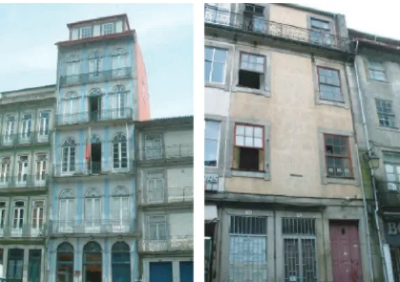
The buildings of Porto historical centre were mostly built between the XVII and XIX centuries, evolving from older constructions. They present a rectangular plant, with a narrow front, a long depth and a variable height: an average of 3 to 4 floors and a maximum of 8 floors (the top floors being usually added afterwards); the architecture of the inside is quite repetitive, usually with staircases at the centre, toped by a roof skylight, one compartment turned to the front and one to the back of the building, Figure 3.
These constructions that normally belonged to the popular and bourgeois branch of the population aren’t exclusive from Porto and exist all over Portugal and in different European countries. Porto uniqueness resides in the fact that, in the old part of the city the slen-der houses represent almost the totality of the civil buildings.
2.2 Building structural scheme
The structural schemes of these buildings are also quite typical, consisting of four stone masonry walls
Figure 3. Main façades of two XIX century buildings at São Domingos and Lóios squares, Porto.
Figure 4. Beams and transversal bars of a timber floor. São Domingos building, XIX century (1856), Porto.
defining the building contour: the two façades and the two lateral walls. The other walls are usually wooden type panels, sometimes reinforced by a wooden strut-and-tie system that improves its in-plane behaviour and the connection between walls and floors. This internal structure, together with the timber floors and the roof trusses, strongly contributes to the buildings efficient performance under vertical, but particularly under hor-izontal loads. As a result, it is important to ensure a good link between these elements in order to guarantee a good and stable global behaviour.
The floors that are normally supported on the lateral masonry walls consist of a set of circular sec-tion beams (diameters varying between 0,15 m and 0,40 m), spaced 0,60 m, and a secondary transver-sal bar system, Figure 4. Structural elements with rectangular section can also be found, usually as the result of interventions performed after the beginning of the XX century. The most common species used on the construction of floors were chestnut, oak, pine and eucalyptus. However, floors executed with other species also exist.
The timber roofs present variable configurations, depending on the size of the building. As the spans were normally lower than 6 m, the structure was very simple, with wooden trusses constituted by two rafters and a tie beam. In other situations, trusses with two
Figure 5. Timber roof structure. António Carneiro building, XX century (1916), Porto.
rafters, two struts, a hanging and a tie beam were used, Figure 5. These elements have circular sections with diameters varying between 0,10 m and 0,30 m and the wood species used in its construction are the same of the floors.
2.3 Common structural damages
Concerning timber structures, this type of buildings presents well defined structural damages. In relation to the timber floors, two main damages can be iden-tified: shear failure at beam extremities in the stone masonry walls, due to the reduction of section from biotic attacks (insects and dry rot fungus) associated to high moisture contents; bending failure at mid-span, originated by the presence of defects, drying cracks, reduction of section due to biotic attacks, excess of load from changes of use, etc. This degradation, asso-ciated to the wood fluency, is often responsible for the excessive deformation of the floors. Besides this defor-mation, the floors can exhibit excessive vibration, normally caused by a deficient transversal bar sys-tem, insufficient beam sections or excessive spacing between beams, etc.
As for the timber elements of roof structure, besides shear failure at the beam extremities, similar to what happens to the floors, it is not unusual to find biotic attacks. As a matter of fact, the roof timber elements present a great potential of biotic attacks, as they are more exposed to the atmospheric agents. Deforma-tion due to fluency is also observed and, if not taken into account, it contributes seriously to the entrance of water in the buildings.
Although one can not generalize, some buildings have suffered structural modifications, in particular after the middle of the XX century, with implications on the structure global behaviour. In the case of the XIX century São Domingos building, the wood stairs of the building at the level of the first floor were removed, with the objective of extending the room space for commercial purposes. This alteration caused an increase of load on the floors, which, together with the lack of the under stairs structure, caused important deformation of the upper floors towards the buildings central area i.e., the staircase, Figure 6.
Figure 6. Deformation of timber floor. São Domingos building, XIX century (1856), Porto.
3 THE ANALYSIS PHASE
3.1 Introduction
The rehabilitation of existing constructions asks for a methodology that includes the steps of Analysis (involving the technical inspection), Diagnosis, Ther-apy and Control. The first two are essential for a correct intervention as they help defining both technologies and materials that better suit the characteristics of the construction (Ilharco, 2007). The results from these phases appear on technical reports, which are the fun-damental asset for support of the intervention options (Therapy and Control). Simultaneously, they are an important instrument of the decision making process, contributing to the knowledge increase on the building and highlighting the different approaches and interests of each area of expertise.
The first of these phases consists on the detailed analysis of the construction, which is obtained throughout an exhaustive technical inspection. It involves the analysis of the construction from a global to a detailed level, supplying information about the critical areas and constructive elements needing inter-vention (Costa, 2006).
In this point, the procedures and tools of the anal-ysis phase, such as geometrical and photographic registries, information about the construction his-tory and, specially, the visual inspection, will be focused. The complementary means of diagnosis, such as non destructive tests (NDT), will be referred in point 4. Finally, a case of a building where the floors would be demolished by the owner will be presented in point 5. In this building, a campaign of tests (non-destructive and destructive) was performed with scientific purposes.
3.2 Previous works
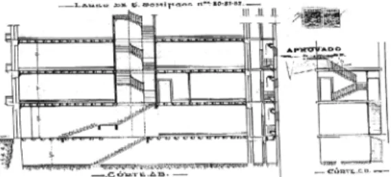
The first step of a construction diagnosis process con-sists on the gathering of information, aiming to know its historical and architectonical context. Generally, it is possible to obtain information from construction licenses and plans at the municipal archives, Figure 7. This information, together with other data about, for instance, modifications on the building initial project, is essential. It can reveal constructive solutions and
Figure 7. XX century (1946) refurbishment project of São Domingos building, XIX century (1856). Porto historical municipal archive.
structural schemes that sometimes are hardly recog-nizable without that input. In some buildings, the consultation of the old projects makes easier the per-ception of structural alterations to the initial project, contributing to the understanding of many observed damages. The reading of old manuals that refer to construction technologies used at the buildings time period is another helpful instrument.
3.3 Visual inspection
The visual inspection of the constructions has the main objective of surveying the characteristics and the damage of the structural and non-structural ele-ments. Data such as the dimension and materials of the structural elements of floors, roofs and walls, the type of wall-floor-roof connections, etc., is essential to understand the building structural schemes and global behaviour. The information about the structural elements can always be completed with a campaign of non destructive or medium destructive tests. The collected information is normally represented on the structural plans of the building, together with cross sections or other useful drawings, to make easier its reading and understanding by all the involved exper-tises. When numerical analyses are needed, this data is also essential to construct the models of the building.
4 DIAGNOSIS COMPLEMENTARY METHODS
NON DESTRUCTIVE TESTING 4.1 Introduction
Nowadays there are many instruments that allow a fast and non-intrusive evaluation of the physical state of timber elements and, at the same time, the estimation of the physical and mechanical properties of the material. A brief description of equipment used in non destruc-tive testing campaigns (NDT) carried out by NCREP is made.
4.2 Hammer, Chisel and Hygrometer
The hammer and the chisel are basic instruments that allow a quick evaluation of the damages of timber
Figure 8. Use of the videoscope for the visualization of a timber floor. Belomonte Palace, XVIII century, Porto. elements. Throughout the comparison between the sound originated by the impact of a hammer in a healthy and in a deteriorated piece of wood, it is possi-ble to distinguish the existence of rotten parts (cavities, cracks, etc.). On the other hand, with the chisel it is pos-sible to evaluate the superficial hardness of the wood and its integrity.
The Hygrometer allows the estimation of the mois-ture content of the wood, contributing to the perception of the potential for biotic attacks. High moisture contents may reveal deficiencies in façades or, in particular, on roof structures. This instrument allows technicians to act preventively in order to eliminate water infiltrations.
On the inspection of a XIX century building tim-ber roof, a moisture content of about 20% indicated the existence of water infiltration responsible for the presence of biotic attacks (termite). On an early XX century building, the 18% moisture content found on a timber floor, together with poor ventilation condi-tions, was responsible for the appearance of the dry rot fungus Serpula Lacrymans.
4.3 Videoscope
The Videoscope is an instrument that allows the observation of hidden areas or of difficult access, Fig-ure 8. This instrument allows us to observe timber floor structures through small holes or gaps. For instance, in Belomonte Palace, an imposing XVIII century build-ing that needed urgent rehabilitation measures, the Videoscope was a precious help, enabling the obser-vation of some floor frameworks and the detection of metallic reinforcements and the presence of biotic attacks without the need to remove the floorboard. With this visualization it was possible to conclude, without any damage for the structure, that it wasn’t necessary to reinforce the beams, but only to provide a curative treatment against insects.
4.4 Resistograph
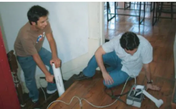
In several timber floors and roofs it has been used the Resistograph (model E300), an instrument that relates
Figure 9. Use of the resistograph on wood stairs. São Domingos building. XIX century (1856), Porto.
the energy spent by the penetration of a needle in a wood element with the material resistance to drilling, Figure 9. The fact of carrying out barely impercep-tible drills, without any influence in the mechanical resistance of the piece, turns this instrument into one of the most used in timber structures survey. In order to guarantee the adaptation to the majority of timber structures, it has been used a 300 mm length needle and adopted a speed of penetration of 5 cm/minute.
With Resistograph results it is possible to detect density variations and internal defects (voids, cracks, etc.) along the cross sections of the structural elements. Results can be easily understood and provide interest-ing qualitative information, as they give draw registries of the variation of wood drilling resistance. However, there are some significant limitations in the use of this instrument to achieve quantitative values, since there are experimental studies only for some species and nei-ther all correlations between the results obtained by the Resistograph and the mechanical or physical charac-teristics of the wood are acceptable. Nevertheless, the characteristic which presents better correlations is the density and it’s possible to obtain a profile of its radial variation along the drilling, namely, the differences of density between the initial lumber (Spring) and the final lumber (Fall), as well as the referred losses of density due to degradations/voids (Botelho, 2006).
As a result of its use, it was possible, for instance, to verify that the timber floors and stairs of a XIX cen-tury (1856) building, located in São Domingos square, were in excellent state of conservation, therefore not demanding reinforcement measures. On other hand, in the timber roof of Belomonte Palace, a building around 300 years old, some interior voids were discov-ered in the supports of tie beams (diameter of 0,30 m) with around half of its cross-section. The extension of the degradation along the elements was evaluated, allowing estimating the length of a future prosthesis to install (Faria, 2002). In Figure 10 illustrates the results given by the Resistograph, where a quite long void on the radial profile of one of the tested elements was
Figure 10. Results from the resistograph on a tie beam of a wood truss of Belomonte Palace, XVIII century, Porto.
Figure 11. Pilodyn used in a timber floor. António Carneiro building, XX century (1916), Porto.
detected. Once again, the qualitative information is very helpful, since it estimates the extension of existent degraded material along the cross section.
To obtain quantitative values it’s necessary to per-form a statistical handling of the results, obtaining a medium value, called Value of Resistograph (VR). After that, and if applicable to the wood specie of the element, it can be used one of the several studies that correlates this value (VR) with physical or mechani-cal parameters of that wood specie, such as the density (ρ), the strength (fc,90) and the modulus of elasticity
(Ec,90), obtained in laboratory tests. Despite the poor
correlations that were usually found, in particular with the mechanical parameters (fc,90and Ec,90), there are
some acceptable correlations. For instance, Botelho (2006) reached a correlation R2= 70,09% between
wood density and VR for Pinus radiate. 4.5 Pilodyn
Another commonly used instrument in the survey of timber floors and roofs is called Pilodyn and has a functioning similar to the concrete Shmidt Hammer, Figure 11. With this instrument it’s possible to achieve physical parameters of the wood, such as density, from correlations with the superficial hardness or, by other words, with wood superficial penetration resistance. It’s used in the detection of illness manifestations through periodic measurements, in the establishment of resistance classes and categories, and productivity parameters in relation to the density between different wood species (Feio, 2005).
In the surveyed structures, the Pilodyn allowed finding wood defects through the reduction of the wood resistance to the penetration of the needle.
Measurements are made on different points of struc-tural elements (middle spam and supports) and on different structural elements with the objective of doing, with a large number of surveyed structures, comparative studies about the elements integrity.
It is important to refer that, due to the short num-ber of existing correlations for the different species, it isn’t possible to reach quantitative values, but only qualitative, but even so valuable information about the conservation state of timber elements.
Most of the correlations for the values obtained by this equipment relates the superficial hardness only with the wood density and not with mechanical proper-ties, which ends up being a disadvantage. On the other hand, the majority of the experimental tests showed that the moisture content considerably affects the depth of penetration (Bonamini et al., 2001) and, so, it’s important to evaluate correctly the wood moisture content. Görlacher (1987) obtained good correlations (R2= 0,74–0,92) between the density and the depth
of penetration of the Pilodyn for an high number of measurements. Furthermore, Feio (2005) found some correlation not only for the density, but also for the modulus of elasticity and the strength of the chestnut wood (Castanea Sativa, Mill). However, and although for the density the correlation is acceptable, for the modulus of elasticity, Ec,90, as for the strength, fc,90,
the estimated correlations are poor, and the author does not advise its use as a quantitative measure. Turrini and Piazza (1983) proposed empirical relations between the impact force and the modulus of elasticity, adopt-ing a factor of reduction for the modulus of elasticity based on the visual classification of the elements: 0,8 for elements without defects and 0,5 for elements with some knots and small degraded areas.
4.6 Seismographs
The seismographs are instruments used frequently by NCREP in the inspection of timber floors. In partic-ular, two 18 bits resolution seismographs have been used, Figure 12. They include tri-axial accelerome-ters, and an autonomous memory. The transference of the information to a computer allows afterwards sign analysis. Readings are done in different loca-tions on a floor, supplying its natural frequencies. This evaluation permits estimating the floor stiffness and, consequently, the efficiency of its structure or its physical and (or) material state.
4.7 Load tests
The load tests allow an in-situ realistic evaluation of the stiffness of a structure and, in particular, of the capacity of a structure to resist a certain load. These are expensive tests that are used by NCREP whenever considered convenient. The tests are normally done for loads of about 1,5x the service load and consists on the
Figure 12. Seismograph used by NCREP.
application of controlled loading and unloading cycles with continuous force and displacement monitoring. It is important to refer that after unloading no important residual deformations should exist on the structure. Thus, before carrying out such a test, it’s important to estimate, numerically or not, its behaviour, trying to avoid surpassing the structure elastic range. In chap-ter 5 a case of a building in which a load test was performed is presented.
5 ANTÓNIO CARNEIRO BUILDING A CASE
STUDY 5.1 Introduction
In one of the buildings analyzed by NCREP the possibility of performing destructive and medium-destructive tests on the floors came up because, due to architectonical incompatibilities, the general project dictated its demolition. The adoption of destructive tests is naturally to avoid, because it doesn’t allow the tested elements to be maintained. However, this opportunity of testing a set of floors that would be demolished ended up being extremely important, since it allowed the evaluation of parameters and character-istics that will surely be helpful in similar structural rehabilitations.
The surveyed building, built in 1916, has an area of 12,0× 30,0 m2and presents floors with 0,20 m
diam-eter beams, spaced 0,60 m and with 6,0 m span. Above the beams there is a 2,5 cm thick floorboard. Perform-ing the transversal link, there are 0,10 m diameter bars, spaced 2,0 m.
Besides a campaign of non destructive tests carried out with the Pilodyn and the seismographs, among other instruments, a load test was then performed together with a very particular test for the evaluation of the beam-wall friction, using a hydraulic actuator.
The campaign of tests, in particular the load test and the frequencies evaluation, had the main goal of assessing the global floor and the single beams behaviour when submitted to a monotonic loading his-tory. The setup was also prepared to allow evaluating the effectiveness of the transversal bar system and the floorboard contribution to the stiffness and resistance of the floor.
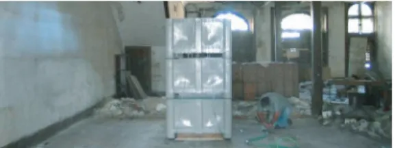
Figure 13. Load test on a timber floor. António Carneiro building, XX century (1916), Porto.
5.2 Load test
The strength capacity and the stiffness of the floors are strongly affected by factors such as the moisture content and the malfunctioning or degradation of its structural elements, beams and transversal bars, and of the floorboard. The load test was carried with the main purpose of evaluating the structural behaviour of the floor and the contribution of its single elements to its global resistance and stiffness, Figure 13. In order to better understand and to be more conclusive about the floors behaviour, the test was done on a 3,5 m wide strip (corresponding to an assembly of 7 beams) that was isolated from the rest of the floor. It was chosen a well preserved floor area (beams, transversal bars and floorboard).
With the purpose of estimating the efficacy of the transversal bars and the floorboard on the distribution of the loads, only the central beam was loaded. Three reservoirs with a capacity of 600 kg each, making up a total load of 1,80 tons were used. A flow measurement instrument was installed at the entrance of the reser-voirs to control and register the volume of water i.e., the load installed on the floor. During the loading pro-cess, the vertical displacements of all the 7 floor beams were monitored using LVDT’s. The data, load and dis-placements, was acquired continuously and analysed using an on-line homemade software.
Having in mind the objectives referred previously, the tests were done under three conditions: (a) with the original floor, i.e. with transversal bars and floor-board; (b) without the transversal bars i.e., only with the beams and the floorboard; (c) on an isolated beam. Therefore, the load test, which is normally non destruc-tive, ended up to have a destructive character. In order to proceed to the sequence (a) to (c), the test remained within the elastic behaviour range. However, with the intention of complementing the obtained information, a load test will be done at the Laboratory of Earth-quake and Structural Engineering (LESE) to evaluate the ultimate behaviour of the isolated beams.
The analysis of the results, in particular of the load-displacement diagrams, and for the applied load range, shows a linear behaviour, Figure 14. From the results obtained it was possible to estimate the wood modulus of elasticity (around 12 GPa), verify the increase of
Figure 14. Load-displacement diagram for two isolated beams loaded simultaneously (the load refers to the total load applied).
Figure 15. Seismograph used in single beam.
the floor stiffness conferred by the floorboard and the poor effectiveness of the transverse bars to distribute the applied loads when compared to the floorboard. Other conclusions and analyses from the test will be published in the future.
5.3 Seismographs
The data from the seismographs were particularly help-ful in the evaluation of the relative importance of floor elements. In particular, several readings were made. Firstly, the floor with the original width was analyzed (30,0 m); Secondly, the measurements were repeated after the cut that isolated the 3,5 m strip from the rest of the floor, (final area of 6,0× 3,5 m2). Afterwards,
measurements were done without the transversal bars and, finally, on an isolated beam, Figure 15. The com-parison between the results of these four situations, with the main natural frequency changing from 7,0 Hz to 10,0 Hz, allowed evaluating the importance of the floorboard, transversal bars and beams, to the floor structural behaviour and, simultaneously, estimating the medium values of the wood modulus of elastic-ity. It was also verified that the values of the natural frequencies measured in-situ were within the range of theoretical values calculated according to EC5 (1998). Apart from these conclusions, the measurements using the seismographs can be used to calibrate numer-ical models to simulate such type of timber floors on old buildings. When needed, the simulation of the floors can be done considering the beams and the transversal bars as they exist on the floor, and adopting
Figure 16. Beam wall friction test using a hydraulic actuator.
auxiliary bars, with small inertia, to simulate the floor-board, linking the beams. Another possible model, that tends to approach the floorboard real effect over the whole structure, consists on considering low thick-ness slab elements to simulate the floorboard. These elements rest on the beams and transversal bars, but aren’t connected to the resistant walls, as it is usually observed in buildings (Neves, 2004).
5.4 Beam-wall friction test
To evaluate the resistance of the friction connections between the timber beams and the masonry walls, a destructive test was carried out. A segment of beam was cut of to install a hydraulic actuator that would act along the beam axis. In order to maintain the two segments of the tested beam in the original position, it was conceived a metallic structure with pulleys to support it (not allowing vertical movements but free horizontal displacements), Figure 16. To set the actu-ator on the beam, metallic corner cupboards fastened by M12 bolts were used. The test consisted on apply-ing pull out and in movements of the beam in relation to the wall. Displacement transducers were installed at the extremities of the beam to evaluate the load-displacement diagram of the beam-wall connection. With the purpose of verifying any possible horizon-tal movement of the wall during the test, transducers were installed on the walls. The results permitted to conclude about the limited efficacy of the connection between the two elements, traduced by a friction force of about 2,0 kN.
6 CONCLUSIONS
To allow the preservation of Porto Historical Centre buildings (UNESCO World Built Heritage), NCREP-FEUP has participated in many projects, analysing the state of conservation of their structural elements. The present paper refers to the work developed on the anal-ysis of timber structures, floors and roofs, namely on the Inspection and Diagnosis phases. It was concluded that, with the joint use of several non destructive testing
techniques, it is possible to withdraw helpful informa-tion about structural timber elements. Nevertheless, some limitations were verified in their utilization due to the difficulty to estimate quantitative values for mechanical and physical parameters.
To be used in a more trustworthy way, the Resisto-graph and the Pilodyn need experimental studies with different wood species to create newer correlations. Nevertheless, these instruments were very helpful in the accomplishing of qualitative parameters, in partic-ular in the perception of degraded areas, with voids or cracks. In particular, the Resistograph permitted to find voids inside structural elements that apparently were in good state of conservation. On the other hand, the Pilodyn allowed, through tests on different struc-tural elements, to conclude about their relative state of conservation through superficial hardness.
In addition, the use of seismographs on timber floors permits the measurement of natural frequen-cies and, consequently, the estimation of the average modulus of elasticity. In the future, with the infor-mation collected on different surveyed floors, it will be possible to organize a database that will allow us to establish correlations between the measured values and the integrity of the floor.
Finally, it is important to refer that medium-destructive and medium-destructive tests, despite of being applied only under particular conditions, can be an important contribution for the knowledge on the mate-rials and structures. In particular, the load test that, in this case, had a destructive character, allowed estimat-ing the floorboard contribution to the floor stiffness, as well as verifying the low efficiency of the transver-sal bars on the distribution of vertical loads. The beam-wall friction test, only possible with the cut of the tested beam, allowed concluding about the weak contact conditions between the timber beam and the masonry wall.
REFERENCES
Botelho, J. 2006 – Avaliação não destrutiva da capacidade resistente de estruturas de Madeira de edifícios anti-gos. Tese de Mestrado em Reabilitação do Património Edificado. Universidade Porto – Faculdade Engenharia. Portugal.
Costa, A., Ornelas, C., Paupério, E., Guedes, J., Ilharco, T. 2006. A Inspecção como Instrumento de Decisão.
Apre-sentação de um Caso Prático num Edifício com Valor Patrimonial. Patorreb 2006. Porto.
ENV 1995-1-4. 1998. Eurocode 5 – Design of Timber Struc-tures Part 1-1: General – Common rules and rules for buildings.
Faria, A. 2002, Reabilitação de Coberturas em madeira em
edifícios históricos. A Intervenção no Património; Práticas
de Conservação e Reabilitação, Porto.
Feio, A. 2005 – Inspection and Diagnosis of Historical Timber Structures: NDT Correlations and Structural. Tese
de Doutoramento em Engenharia Civil, Universidade do Minho – Escola de Engenharia. Portugal.
Google Earth, Google.
Gorlacher, R. 1987. Non destructive testing of wood: an
in-situ method for determination of density. Holz as
Roh-und Werkstoff. Vol. 45.
Ilharco, T., Romão, X., Paupério, E., Guedes, J., Costa, A. 2007. Organization of information on Built Heritage using
Multimedia Technologies. Euro-Mediterranean
Confer-ence Traditional Mediterranean Architecture. Barcelona. Neves, N., Costa, A., Arêde, A. 2004. Identificação
Dinâmica e Análise do Comportamento Sísmico de um quarteirão localizado na cidade da Horta – Ilha do Faial.
Sísmica 2004. Porto.
Turrini, G., Piazza, M. 1983. Il recupero dei solai in legno. Esperienze e realizzazioni”. Recuperare, Vol. 7.