Behaviour in Aneurysm Models
J. Ribeiro1,2, C.S. Fernandes1, and R. Lima3,4(&)
1
Polytechnic Institute of Bragança, ESTiG/IPB, C. Sta. Apolonia, 5301-857 Bragança, Portugal
2
LAETA, INEGI, Porto, Portugal
3
MEtRiCS, Mechanical Engineering Department, University of Minho, Campus de Azurém, 4800-058 Guimarães, Portugal
CEFT, Faculdade de Engenharia da Universidade do Porto (FEUP), Ruas Dr. Roberto Frias, 4200-465 Porto, Portugal
The aneurysm is a fragile region on the wall of a blood vessel that causes it to form a bulge. In limiting situations, this weakening can lead to vessel disruption. The main goal of this work was to understand how the deformation of the aneurysm occurs when subjected to an internal pressure similar to blood pressure. The strain state of the aneurysm will allow to define which regions are subject to higher stresses and which can give an indication of potential rupture. To carry out this study we have employed a numerical approach using a commercial software (Ansys®). With this software the pressure caused by the fluid was calculated using known parameters through the experimental measurement of the pressure drop. It was possible to define a velocity profile for thefluid and to characterize itsflow through the channel. The aneurysm was subjected to a pressure previously determined for thefluid, simulating the pressure to which the channel is subjected by the bloodstream. Note that the current study have always taken into consideration that the blood vessels have a hyperelastic behaviour, defined through experimental stress/strain curves. Analysing the obtained results, it was verified that the expansion of the aneurysm is predominant in its lateral regions where the greater strain values were obtained. In these regions is where a greater risk of vessel rupture can occur.
1 Introduction
Aneurysms are the fourth most frequent cause of cerebrovascular disease in adults, following ischemic, thrombotic and hypertensive cerebral haemorrhage, a fact that is of the utmost importance, considering that in Portugal cerebrovascular diseases are the main cause of mortality [1]. One of the main causes for the appearance of aneurysms is the deterioration of the arterial wall mainly due to hypertension. Other causes include hereditary connective tissue diseases, congenital cardiovascular anomalies, or arte-riosclerosis [2].
©Springer International Publishing AG 2018
Despite the large research studies in thisfield, ways to prevent the formation and growth of aneurysms are still lacking. An approach to study the behaviour of aneurysms can be made from the analysis of the bloodflow behaviour at this region and the wall deformation occurred by the blood pressure. One of the main concerns of thisfield relates to the mechanical properties of the tissues that are present in the walls of arteries. Several studies have shown that the tissues of the arteries have a typically hyperelastic behaviour
[3–5]. These materials are characterized by the high deformations that they exhibit before
reaching the tensile strength [2]. In order tofind a material with hyperelastic properties close to arterial tissues, aneurysms in vitro models made of polydimethylsiloxane (PDMS) are gaining popularity among the biomedical research community [6–9]. PDMS is a biomaterial known for its biocompatibility and low cost, which makes this material extremely popular in several biomedical applications, such as the development of biomedical microfluidic devices and organs-on-a-chip platforms [10–14].
In the present study we have carried out numerical simulations to analyse the strain field of the aneurysm wall caused by the internal pressure of the fluid flow. The numerical analysis was based on afinite element method, a computational technique that, due to the development of robust and optimized algorithms, allows simulations with high accuracy and precision results. The numerical approach has the advantage of reducing the experimental tests that normally can be extremely time-consuming, laborious and costly [8]. The numerical method used in the present study, allows to test the characteristics of previously known hyperelastic materials by using mathematical models suitable for these kind of materials. In this analysis velocity profiles of afluid flowing through aneurysm model will be obtained. Note that the fluid used in the present study was glycerine in order to compare with experimental tests performed with in vitro models with geometries similar to the one used in this study [8,9].
2 Numerical Simulation
For numerical simulations, a commercial code, Ansys®, was used. In the case under study, two different modules were used:fluidflow (Fluent) and structural (Structural). One of the great advantages of this program is the possibility of integrating different analyses and, therefore, using the results obtained from one simulation to the other. In this particular case, the pressure exerted by thefluid on the channel walls was used to determine the displacements and strains resulting from the pressure. The models used in numerical simulation were previously drawn in a CAD software called Solid-Works®. After obtaining the three-dimensional model in the CAD software, the model was converted to a parasolid extension. The geometries used in the simulations intend to reproduce the channel used in an experimental study of Rodrigues et al. [9], and it is presented in Fig.1.
Forflow simulations, only the inner channel was used, that is, the base presented in Fig.1 was discard and the thickness of the channel was also ignored. The mainflow direction was the positive z-axis.
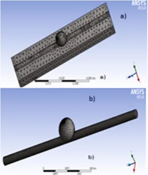
During the pre-processing the geometry previously created in parasolid was imported. In this phase of the simulation the mesh was also automatically generated with a high refinement, both in the simulation of the fluidflow and in the structural part. Figure2 shows the generated meshes for the different simulations.
Fig. 1. Geometry of the studied channel.
In the discretization of structural geometry model, Fig.2a, the element Solid 187 was implemented, and the number of elements is 10934. The model used in thefluid flow simulation, Fig.2b, was discretized using tetrahedral elements, the resulting mesh being constituted by 58239 tetrahedral elements.
The laminar incompressible stationaryfluidflow simulation was performed using thefinite volume commercial software package ANSYS-FLUENT®. For that, it was necessary to import the geometries corresponding to the interior of the experimentally models used by Rodrigues et al. [9], which corresponds to the channels through which thefluidflows. For the pre-processing, in addition to the geometry and properties of the used fluid, it was necessary to stablish the boundary conditions. The boundary con-ditions were obtained from a set of parameters that were measured directly in the experimental test [9] or calculated from some of these measurements. Simulation was carried out for glycerine, thefluid used in the experimental work referred before, and their properties were found in the Ansys database.
As boundary conditions, aflow rate of 300µL/min was imposed in the inlet of the channel and no-slip at the wall was admitted, as the measured drop pressure was 389.6 Pa the inner pressure was calculated by 100935.5 Pa. After the pre-processing phase, the processing was implemented, being carefully verified the convergence of the calculations. It was observed that 500 iterations allows to obtain the desired conver-gence of the simulation.
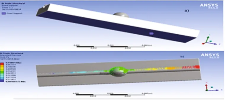
One of the results obtained in the simulation of the fluid flow was the pressure variation along the channel with aneurysm. This pressure value was used to study the mechanical behaviour of the aneurysm walls. To assign the hyperelastic behaviour, we have used stress/strain curves obtained experimentally, and the constitutive model of Mooney-Rivlin with 2-parameter constitutive model was applied to represent the behaviour of the PDMS. As boundary conditions, the base of the model was considered fixed and the internal pressure applied to channel wall was the one previously deter-mined in the glycerine flow simulation. In Fig.3 is possible to observe the used boundary conditions.
Following the introduction of the boundary conditions referred above, the data were processed. As simulation involves large displacements, there was the need to ensure convergence to a solution and for this particular study it has been achieved after 149 iterations.
Fig. 3. Boundary conditions for the aneurysm model: (a) on the base and (b) internal pressure.
3 Results and Discussion
In thefluidflow analysis, properties such as pressure and velocity were studied. Observing Fig.4, it can be seen that thefluid in the channel with the aneurysm does not show great differences of pressure in all its extension, mainly in the space between the wall and the centre.
Fig. 4. Static pressure distribution in the wall of the channel used inflow simulation.
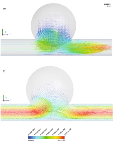
Fig. 5. Velocity vectors for the studiedflow: (a) In the channel; (b) In the central plane of the
Analysing Fig.5, it is possible to observe that the velocity of the fluid changes along the channel, where the lowest velocities are around the walls of the channel and the highest at the centre of the channel inlet and outlet region. Note that overall the lower velocities are within the aneurysm region, as expected, due to the geometrical properties of the channel and boundary conditions used in the study.
For the operating condition used in the present study it was also possible to observe, Fig.5, the inexistence of recirculation inner the aneurysm, the flow pattern being influenced only by the geometry of the channel.
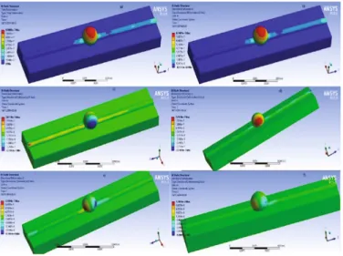
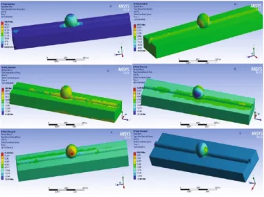
The structural simulation allow us to analyse the displacement and stress fields caused by the internal pressure in the channel. Observing the displacements of Fig.6 and comparing with the displacements on the region of the single channel, it can be concluded that the aneurysm influences the displacement in the remaining channel. The influence of the aneurysm is also visible in the maximum displacement values, since they are well above those of the single channel region. The maximum displacements in the upper part of the aneurysm are shown in Fig.6a. However, according to the displacements in Y, the maximum values are on the lateral side of the aneurysm.
In Fig.7it is possible to observe the stressfield for the same geometry. The Von Mises equivalent stress shows its maximum values in the channel in the region of transition between the aneurysm and linear channel, and minimum values in the upper part of the aneurysm bubble. The stresses in the transition region of the aneurysm are always the highest, while the upper part of the aneurysm always presents with lower stresses. For the stress in the Z direction, the maximum values are observed on one side of the aneurysm.
Fig. 6. Field of displacements in the aneurysm channel: (a) Total displacement; (b) According
to the direction X; (c) According to the direction Y; (d) Direction Y seen from the other side; (e) According to the direction Z; (f) Direction Z seen from the other side.
4 Conclusions
Numerical simulations of stationary laminar incompressible glycerineflow in a circular channel with aneurysm was performed in order to obtain the pressure distribution at the wall, these result being then used as boundary condition for a structural analysis of the wall channel. The calculations were performed in a commercial software using two different modules of Ansys®: Fluent and Structural. In thefirst module the glycerine flow, commonly used as a blood analogue, was analysed inside a closed channel. For the second module it was also analysed the displacement and stressfields produced by the internal pressures obtained fromfluidflow simulations. In the developed model it was considered that the material had a hyperelastic behaviour, and as a result it was used the stress-strain curve obtained experimentally for the PDMS material and implemented the constitutive model of Mooney-Rivlin.
From the velocity profiles obtained from the numerical simulations it was possible to observe that velocities were close to zero around the walls and they increase through the centre of the channel. Overall, it was observed that the expansion of the aneurysm is predominant at its lateral regions, and that the higher deformations, where there is a greater risk of rupture, tends to occur exactly in these zones.
Acknowledgments. The authors acknowledge thefinancial support provided by Fundação para
a Ciência e a Tecnologia (FCT), COMPETE, and FEDER through the project POCI-01–
0145-FEDER-016861 (with associated reference PTDC/QEQ-FTT/4287/2014) funded by COMPETE2020—Programa Operacional Competitividade e Internacionalizacao (POCI) with
thefinancial support of FCT/MTES through national funds (PIDDAC) and by the project Nos. UID/EMS/00532/2013, and UID/EMS/04077/2013.
Fig. 7. Stressfields in the aneurysm channel: (a) Von-Mises equivalent stresses; (b) According
References
1. Branco, G., Miguel, J., Goulão, A., Maurício, J.C.: Diagnóstico Angiográfico dos Aneurismas Intracranianos: Estudo Sobre a Experiência do Serviço de Neurologia do Hospital Egas Moniz. Acta Médica Portuguesa5, 515–518 (1992)
2. Faleiro, L.C.M., Pimenta, N.J.G., Faleiro, R.M., Costa, R.A., Esmeraldo, A.C.: Tratamento Cirúrgico dos Aneurismas não Rotos da Artéria Cerebral Média. In: Arquivos de Neuro-Psiquiatria, vol. 62, No. 2. São Paulo, Junho (2004)
3. Holzapfel, Gerhard A., Weizsäcker, Hans W.: Biomechanical behavior of the arterial wall and its numerical characterization. Comput. Biol. Med.28(4), 377–392 (1998)
4. Gasser, T.C., Ogden, R.W., Holzapfel, G.A.: Hyperelastic modelling of arterial layers with distributed collagenfibre orientations. J. Roy. Soc. Interface3(6), 15–35 (2006)
5. Masson, I., Boutouyrie, P., Laurent, S., Humphrey, J.D., Zidi, M.: Characterization of arterial wall mechanical behavior and stresses from human clinical data. J. Biomech.41(12), 2618–2627 (2008)
6. Queijo, L., Lima, R.: PDMS anatomical realistic models for hemodynamic studies using rapid prototyping technology. In: IFMBE Proceedings. IFMBE, vol. 31, pp. 434–437 (2010)
7. Yu, C., Matsumoto, K., Shida, S., Kim, D.J., Ohta, M.: A steadyflow analsys on a cerebral aneurysm model with several stents for new stent design using PIV. J. Mech. Sci. Technol.
26(5), 1333–1340 (2012)
8. Pinho, D., Bento, D., Ribeiro, J., Lima, R., Vaz, M.: An in vitro experimental evaluation of the displacementfield in an intracranial aneurysm model. In: Flores, P., Viadero, F. (eds.) New Trends in Mechanism and Machine Science, Mechanisms and Machine Science, vol. 24, pp. 261–268. Springer, New York (2015)
9. Rodrigues, R.O., Pinho, D., Bento, D., Lima, R., Ribeiro, J.: Wall expansion assessment of an intracranial aneurysm model by a 3D digital image correlation system. Measurement88, 262–270 (2016)
10. Bélanger, M.–C., Marois, Y.: Hemocompatibility, biocompatibility, inflammatory and
in vivo studies of primary reference materials low-density polyethylene and polydimethyl-siloxane: a review. J. Biomed. Mater. Res.58(5), 467–477 (2001)
11. Lima, R., Wada, S., Tanaka, S., et al.: In vitro blood flow in a rectangular PDMS microchannel: experimental observations using a confocal micro-PIV system. Biomed. Microdevices10, 153–167 (2008)
12. Faustino, V., Catarino, S.O., Lima, R., Minas, G.: Biomedical microfluidic devices by using low-cost fabrication techniques: a review. J. Biomech.49(11), 2280–2292 (2016)
13. Sackmann, E.K., Fulton, A.L., Beebe, D.J.: The present and future role of microfluidics in biomedical research. Nature507, 181 (2014)
14. Bischoff, J., Arruda, E., Grosh, K.: Finite element modeling of human skin using Na isotropic, nonlinear elastic constitutive model. J. Biomech.33(6), 645–652 (2000)