--=w
J
V\+U\'Ylu-h
U't1~
-d
crvJ\IV\. ~
c5Q
~e..V
t
'LA-
.s;CA
~
A New Proposal of a Simple Model for the Lateral-torsional Buckling
of Unrestrained Steel 1-Beams in case of Fire: Experimental and
Numerical Validation
Vila Real, P. M. M. a*; Piloto, P.A. G.b and Franssen, J.-M .c
a Department of Civil Engineering, University of Aveiro,
3 810 Aveiro, Portugal
Tel.: +351-234-370049; fax: +351-234-370094; e-mail: pvreal@ civil.ua. pt
*
Corresponding authorh Department of Mechanical Engineering, Polytechnic ofBraganc;a, Portugal
c Department Civil Engineering, University of Liege, Belgium
ABS1RACT
The behaviour of Steel 1-Beams exhibiting lateral-torsional buckling at elevated temperature has been
studied by means of experimental and numerical ana(ysis. The authors in an earlier paper have presented
an analytical formula for the buckling resistance moment in the fire design situation. This new proposal,
different from the actual proposal of the Eurocode 3 Part 1.2 has been validated in this work by
comparison with the results fi"om a set of 120 exp erimental and numerical tests pe1jormed on IPE 100
beams, submitted to temperatures v01yingji·om room temperature to 600 "C. The numerical simulations
have been based on the measured geometrical dimensions of the cross sections, the longitudinal
impe1jections, i. e., the out of straightness of the beams, the residual stresses and the y ield strength. Th e
Eurocode simple model promotes ultimate loads that depend mainly on the non-dimensional slenderness
of the beams. The ana(vtical results provided by the Eurocode 3, for a certain range of the slenderness,
appear to be unsafe when compared with the numerical and experimental results. It is shown that the new
NOMENCLATURE
a Maximum amplitude of the beam lateral imperfection
E Young's modulus of elasticity
G Shear modulus of elasticity
Second moments of area about the x, y axes
Torsion section constant
Warping section constant
Yield strength
k Effective length factor
kw
Warping effective length factorky,O,conr Reduction factor for the yield strength at the maximum temperature in the
compression flange
ea
com ' reached at time tkE ecom Reduction factor for the slope of the linear elastic range at the maximum
steel temperature in the compression flange
e
a.com reached at time tL Length of the beams
M Buckling resistance moment in the fire design situation
• b,fi.t.Rd
M er Elastic critical moment for lateral-torsional buckling
M fi,e, nd Design moment resistance of a Class 1 or 2 cross-section with a uniform
temperature 8 a
Jvf W '1R Buckling resistance moment in the fire design situation given by SAFIR
Plastic moment resistance of the gross cross-section, lvf pi.Rd for normal
.
C\ ) I)
J'v! x Bending moment about x axe
I Time
u Lateral displacement
v Vertical displacement
w pl,y Plastic section modulus
-bt;il.l
x, y Principal centroidal axe
z Longitudinal axis through centroid
a. Imperfection factor
a. AI Buckling factor
~ Severity factor
8 Central deflection
E Material Factor
YM o Partial safety factor (usually YAt o
=
1.0)Yu.fi Partial safety factor for the fire situation (usually y u .fi
=
1.0)8 Rotation
<1> Twist rotation
A.
LT
SlendernessILT
Non-dimensional slenderness at room temperatureA. LT ,9,com Non-dimensional slenderness for the maximum temperature m the
compression flange
e
a.comt..LT,fi Non-dimensional slenderness in the fire design situation
1 INTRODUCTION
The behaviour of steel !-beams at elevated temperatures has been analysed numerically1'
2
leading to a new proposal for the evaluation of the lateral-torsional buckling
resistance. This new proposal contains a scalar ~ that has to be calibrated to ensure an
appropriate safety level, which is done in this work throughout a large set of
experimental tests and numerical simulations.
Although the problem oflateral-torsional buckling of steel !-beams at room temperature
is well known3-6 the same problem at elevated temperature is not. Among the work done
in this field there is the paper by Bayley et al .7, who use a three dimensional computer
model to investigate the ultimate behaviour of uniformly heated unrestrained beams. In
their work the computed failure temperature is related to the degree of utilization when
compared with the same temperature given by the Codes, but no analytical proposal is
made for the lateral-torsional buckling resistance moment in fire situation. Nevertheless
the results presented indicate that the Eurocode 3 Part 1.28 overestimates the critical
temperature for unrestrained simple beams in fire resistance calculations, which is in
accordance with the results of the authors for a certain range of the slenderness, as
shown later in this paper.
' •.J ~
vVY
Cf/11/W.\The proposal\.fue present paper pretends to validate was based on the numerical results
from the SAFIR program9, a geometrical and materially non-linear code specially
established to analyse three-dimensional structures, including the effect of warping, in
case of fire. The capability of this code to model the lateral-torsional buckling of beams
has been demonstrated 10 at room temperature by comparisons against the formulas of
the Eurocode 3, Part 1-111. Franssen12 has also compared the SAFIR program with four
program is capable of considering loads placed at any level on a cross-section and it is
also possible to introduce residual stresses owing to the fibre type finite element used.
It must be emphasized that the simple model that this paper wants to validate, presented
by Vila Real et al.1' 2, was established on the base of numerical simulations using
characteristic values for initial out-of-straightness (L/1 000) and residual stresses
( 0.3 x 235 iv!Pa ), which are unlikely to be simultaneously present in a test or in a real
building. In the experimental work, the geometrical imperfections and the residual
stresses were measured as well as the nominal yield strength of the material and the
Young Modulus. These measured values were used in the numerical calculations.
A set of 120 full-scale tests based on a reaction frame and on a hydraulic system has
been carried out for beams of the European series IPE 100 with lengths varying from
0.5 to 6.5 meters. Three tests have been done for each beam lenf,rt:h and for each
temperature level, due to statistics requirements. The beams were electrically heated by
means of ceramic mat elements, heated by a power unit of 70 kV A. A ceramic fibre mat
was used around the beam and the heating elements in order to increase the thermal
efficiency.
2 EXPERIMENTAL AND NUMERICAL CASE STUDY
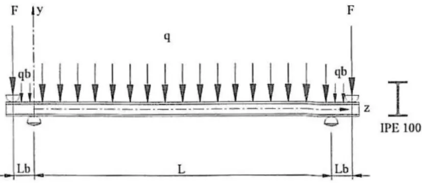
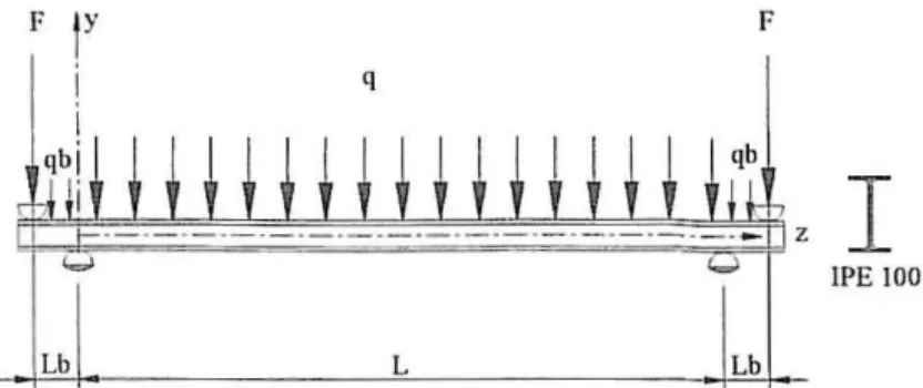
A simply supported beam with fork supports shown in Fig. 1 has been studied. In this
figure, qh represents the self weight of the beam and q represents the additional
distributed load due to the weight of the ceramic mat and electro-ceramic resistances
used.
The experimental set-up is also shown in Fig. 2, where the fork supports, the hydraulic
elements was used in order to ensure a uniform temperature distribution along the
length of the beams. The temperature was measured with thermocouples welded on the
beams at different points of the beam length.
Three types of mid span displacements were experimentally measured as shown in Fig.
3. The vertical displacement, DV, the lateral bottom displacement, DLB and the lateral
top displacement, DLC.
The thermal action was changed from room temperature up to 200, 300, 400, 500 and
600 °C. These temperatures were applied before the mechanical action, with the
longitudinal displacement unrestrained and
ke~ant
during the loading, which isapplied only after the temperature stabilisation.
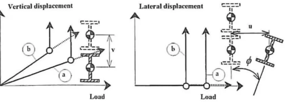
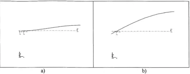
The vertical and lateral displacements vary in a way that is schematised in Fig. 4. As
long as the load on the beam remains bellow the critical value, the beam is stable.
However, as the load is increased a critical value is reached when slightly deflected and
twisted form of equilibrium becomes possible. The initial plane beam configuration is
now unstable, and the lowest load at which this deflected condition occurs is called the
beam critical load.
The stress strain relationship used in the numerical simulation of the experimental tests
is a function of the measured material strength and varies with temperature, according
to Eurocode 3, Part 1-28.
A three-dimensional beam element with 15 degrees of freedom and three nodes has
been used to numerically simulate the behaviour and the buckling moment resistance of
the beams loaded as shown in Fig. 1.
3.1 Lateral torsional buckling according to the Eurocode 3
The design buckling resistance moment of a laterally unrestrained beam with a class 1 or
2 cross section type, in case of fire is given in the Eurocode 3, Part 1.28 by
M
=
Xr.r.Jr w .kf
_I_h,fi,t,Rd l ? pl,.1- y.e.com y
·- y Af./i
(1)
where:
Xr.r .. fi is the reduction factor for lateral-torsional buckling in the fire
design situation, given by
1
~
'X LT.fi
=
I .,r.
?<I> l.T .e,com + \f [<I> LT ,e ,com
r
- [
LT ,e ,com]-(2)
and
1 [ - - " ]
<I> l.T,e.com
=
2
1 + a.(A.LT.e.com -0.2) + (A. LT.e ,com)- (3)w pl,y is the plastic section modulus;
k y.e ,com is the reduction factor for the yield strength at the maximum
temperature in the compression flange 9 a com , reached at time I ;
y AI .fi is the partial safety factor for the fire situation (usually Y,H,fr
=
1).The equation ( 1) is used if the non-dimensional slenderness
I
LT e com for the temperaturereached at timet, exceeds the value of0.4. If the slenderness is lower than this threshold
value, it is considered that no lateral buckling will occur and the full plastic bending
The constant 1.2 is an empirically determined value and is used as a correction factor
that allows for a number of effects.
The reduction factor for lateral-torsional buckling in fire design situation, XLr .. fi, must
be determined in the same way as it is at room temperature, but using the
non-dimensional slenderness A. LT .e.eonr (or
'i:.
LT ,fi , if the temperature field in the cross sectionis uniform) given by
where
k y.e.eonr
k E .e,eonr
(4)
is the non-dimensional slenderness at room temperature gtven
by11 (for Class 1 or Class 2 cross-sections)
where
Ewpl .y ALT
=
1tM er
(5)
(6)
(7)
where M er is the elastic critical moment for lateral-torsional
buckling of the beam. Substituting from (6) and (7) in (5)
_ _
w,,,,f,
_~M
~
A LT - -
-M er M er (8)
where M pi is the plastic moment resistance of the gross
k [!a conr is the reduction factor for the slope of the linear elastic range at
the maximum steel temperature reached at time I.
The imperfection parameter a on equation (3) depends on the type of cross section,
being 0.21 for hot rolled sections or 0.49 for welded cross section8.
3.2
The new proposal
A new proposal for the lateral-torsional buckling resistance, based on numerical
calculations was proposed by Vila Real et al.1' 2. According to this new proposal, and
adopting for the lateral-torsional buckling a similar proposal as the one that Franssen et
al. 13 used to represent the behaviour of axially-loaded columns when submitted to fire
conditions, the design buckling resistance moment of a laterally unrestrained beam with
a class 1 or 2 cross section type, can be calculated by
1
M b .fi.t.Rd
=x
LT,fi w p/,y y,6,<om y 1c .J
-Y u .fi
(9)
wherexLT .. /i , is given by
1
(10)
with
1
r -
-
?]
~ LT ,a,conr = 2 Ll + aJ...LT.6,com + (J...LT,fl,con,)- (11)
The imperfection factor a , in this proposal, is a function of a severity factor
p
a= Pe
(12)The severity factor
p ,
which should be chosen in order to ensure an appropriate safety(13)
where / " represents the nominal yield strength of the material in MP a.
The remaining factors should be calculated as in the Eurocode 38.
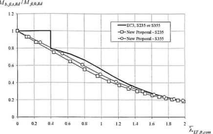
A comparison between this new proposal and the Eurocode 3 formulas is made on Fig.
5. In this figure on the vertical axis the following ratio is marked :
M b.Ji.t.Rd
lvf
=
XL r ,fifi.e.Rd
(14)
where, M b,fi.t,Rd is given by equation (1) or equation (9) and M fi,e.na is the design
moment resistance of a Class 1 or 2 cross-section with a uniform temperature 8 a gtven
by
M _ t YM o M
Ji.e.Ra - tcy.e - - na y Al.fi
( 15)
where, y M O
=
1.0 , y u .. ti=
1. 0 and M na is the plastic resistance of the grosscross-section, M pt,na, for normal temperature, which is given, using y 11., 0 = 1.0, by
w
f
M Rd -- p/ ,y • .1' (16)
Yuo
It can be verified on Fig. 5 that the shape of the buckling curve is different, with the
new one starting from X Lr.fi = 1.0 for f.LT.fi
=
0.0 but decreasing even for very lowslenderness, instead of having a horizontal plateau up to I LT.fi
=
0.4 as in the presentversion of the Eurocode 3 8.
The lateral-torsional buckling curve now depends on the steel grade due to the
parameter c that appears in the imperfection factor as it can be seen in equation ( 13)
4 CRITICAL MOMENT
The critical moment, M er, necessary to evaluate the non-dimensional slenderness
A. LT .o.com, according the Eurocode 3 is obtained solving the following differential
equations5•6
dfJf!L•tbe
( )
11 11
EI.vu" +(M",cj>) =0
11 I
(EI,A>")
-
(Glt4>
1)
+
(M""u")
=o
(17)
which .traduce the lateral-torsional buckling equilibrium of the beam. The first equation
represents the equality at equilibrium between the out-of-plane bending action
11 ( )11
-
(M
A>)
and the flexural resistanceEl/'"
and the second equation represents theequality between the torsion action -M xu", and the warping and torsional resistances
11 I
(Elw<l>")
and -(GI
1<j>1
) • The bending moment distribution
M""
due to the transverseload q varies along the beam and so the differential equations have some variable
coefficients and are difficult to solve5.
It can be verified that these differential equations are satisfied by the substitution of the
buckled shapes formulas:
(18)
where 8 and 9 represent the values of u and <!> at mid-span and z represents the
eo-ordinate along the beam axis.
and taking into account the moment distribution along the buckling length due to the
uniformly distributed load, it can be verified that the critical load F (see Fig. 1) is
function of the material properties, the beam cross section geometric characteristics and
also function of the distributed load. This critical force F when introduced into the
moment distribution. gives the critical moment, M er, at the supports. This moment can
be compared to the critical elastic moment, M
:,b
for the pure bending case using themoment distribution factor a.AI 5'6 as shown in the following equation
?El ( ]
2
(
)?
M =a. M pb = a. 1t- y ~ I w + kL -cl,
er M er M
(kL)2
Jc [ 2 EJw y 1t y
(20)
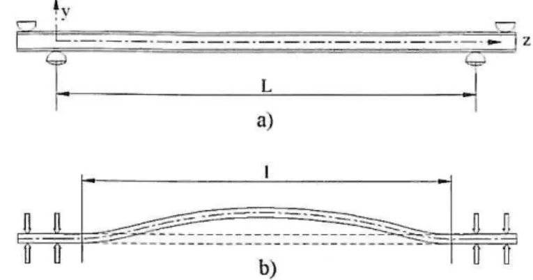
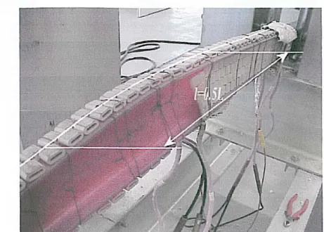
where k represents the effective lateral buckling length factor and k"' the factor which
accounts for the beam end warping. Regarding the type of loading and support
conditions used in the experimental tests, the value of k
=
0.5 has been used torepresent the total restraint of the lateral movement due to the load application process
(see Fig. 6) and the value of k w
=
1 to the free end warping condition.Fig. 7 shows the plan view of the one half deformed beam obtained numerically. It is
clearly shown that when the load application point is laterally restrained the effective
lateral buckling length factor k must be approximately taken as 0.5.
The deformed shape of the beam obtained in the experimental tests is shown in Fig. 8.
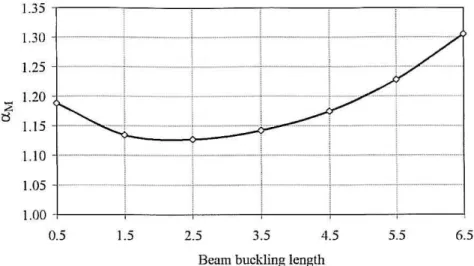
The analytical calculations have shown that the moment distribution factor a.M is not
constant and depends on the buckling length of the tested beam as shown in Fig. 9.
A multifunction reaction structure (Fig. 2) was used to test the beams at elevated
temperatures and to apply the mechanical loads. The loads were applied by means of
two hydraulic jacks with 600 kN of capacity each and the beams were heated using
electric ceramic mats.
Five hundred meters of IPE 100 profile was used, gtvmg 120 beams with lengths
varying from 0.5 to 6.5 meters.
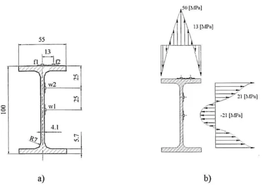
5.1 Residual stresses
The magnitude and geometric distribution of the residual stresses may vary with the
geometry of the cross section and with the straightening and cooling processes. The
residual stresses were measured at four points (fl, f2, w1 and w2) as it is shown in Fig.
10.
The measurements were based on the drill hole method. Strain gauges were used and it
was necessary to introduce a mechanical interference in the system. The requirement of
keeping the disturbance as small as possible is a positive factor in this method. The drill
hole rosette requires a small drill hole of about 1.5 mm in diameter. This can be
regarded as a non-destructive technique [14].
The residual stresses were measured on 10 different beams. Some of the measurements
were not taken into account because the drilling tool broke. The average measured
values were used to represent the residual state of the tested beams and are listed in
table 1.
Two types of geometric imperfections were measured. One related to the cross section
dimensions, measured by digital callipers and the other related to the longitudinal lateral
distance from an imaginary straight line, measured by a laser beam method. In the
numerical modelling, the measured longitudinal imperfections of the beams have been
approximated by the following expression
( ) . (7t XZ)
uz=asmL
(21)where a is the measured maximum amplitude of the lateral imperfection, as is listed in
table 2.
The cross section geometry imperfections were also measured and used in the numerical
calculation.
A set of 31 profiles from the originals 46 was used to measure the cross section
dimension as shown in table 3. The calculated plastic modulus exceeds the foreseen
values based on nominal dimensions.
5.3
Material strength characterisation
A set of 20 tensile specimens extracted from the beams (see Fig. 11) was tested. The
specimens were talcen from the flange and web parts of the IPE 100 beams, and follow
the Portuguese standard NP ENI 0002-1 [ 15]. Yield strength and elastic modulus
evaluation are listed in table 4, with its average values being respectively 320 Mpa and
221 GPa.
Two different types of electro ceramic mat resistances measuring 1220 x 45 and
610 x 85 mm, with a maximum electric power of 2.7 kW each were used to heat the
beams. This material is able to support temperatures up to 1050 °C, although the
experiments were conducted up to 600 °C only and with a heat rate of800 °C/h.
5.5 Lateral buckling resistance moments
The mechanical load was imposed as shown in Fig. 1. After temperature stabilisation a
concentrated load F was increased by amounts of 2000 N until a certain value in which
an increase in the displacement value didn't correspond to a load increase.
The experimental lateral buckling resistance moments are shown in figure 12 for
temperatures varying from room temperature up to 600 °C.
Experimental results for tested temperatures above 400
oc
have been plotted in the samechart as shown in Fig. 13 .
6 NUMERICAL EVALUATION
A set of 120 numerical calculations was made to calculate the buckling resistance
moment at elevated temperatures. A non-linear material and geometrical code, based on
two types of finite elements, made the study of the lateral-torsional buckling of the IPE
1 00 beams possible. Bi-dimensional plane linear elements were used to describe the
temperature field in the cross section of the beams resulting from the thermal action.
The warping function and the torsion stiffhess have been calculated for each
temperature level, according to the experimental measurements of the Young modulus
The numerical lateral buckling resistance moments are shown m Fig. 14 for
temperatures varying from room temperature up to 600 °C.
The resistance moments obtained by numerical simulation for all the temperatures were
plotted in the chart in Fig. 15.
7 EXPERIMENTAL AND NUMERICAL COMPARISONS
Both experimental and numerical results have been compared with the simple formulas
from Eurocode 3 Part 1.2 and the new proposal.
The results ofthese comparisons are shown respectively in Fig. 16 and Fig. 17.
The regression line is much more close to the ideal continuous line in the case of
numerical calculation than for the experimental results but in both cases the number of
unsafe points is smaller when the new proposal is used. From these figures it is clear
that the new proposal with ~ = 0.65 is safer than the Eurocode 3.
8 CONCLUSIONS
The physical fact that elasticity modulus decreases faster than the yield strength
when the temperature increases, plus the fact that the stress-strain relationship at
elevated temperature is not the same as at room temperature, produce a modification of
the lateral-torsional buckling curve at elevated temperature. The horizontal plateau valid
at 20 °C up to a non-dimensional slenderness of 0.4 vanishes at elevated temperatures.
been confirmed and it was shown that the new proposal for lateral-torsional buckling, is
safer than the Eurocode 3 formulas .
ACKNOWLEDGEMENTS
This work was performed m the course of the research project
PRA.XIS/P/ECM/14176/1998 sponsored by the Portuguese Foundation for Science and
Technology. Special thanks to Pro£ Mario Vaz and the enterprise J. Soares Correia are
REFERENCES
l. Vila Real, P. M. M. & Franssen, J.-M., Lateral buckling of steel I beams under fire conditions
-Comparison between the EUROCODE 3 and the SAFIR code, internal report No. 99/02. Institute of
Civil Engineering- Service Ponts et Charpents- ofthe University of Liege, 1999.
2. Vila Real, P. M M. & Franssen, J.-M. , Numerical Modelling of Lateral Buckling of Steel I Beams Under Fire Conditions -Comparison wiU1 Eurocode 3, Vol. 11, No. 2, Journal of Fire Protection
Engineering, USA, 2001, pp. 112-128.
3. Papangelis, J.P.; Tralmir, N.S. & Hancock, G.J., Elastic fle}o,"Ufal-torsional buckling of structures by computer; Journal of Computers and Structures, Vol. 68; Pergamon Press; 1998, 125-137.
4. Timoshenko P.S. & Gere J.M., TheoiJ' of elastic stability; McGraw Hill Intern. Editions, 1963. 5. Traltair N.S., Flexural - Torsional Buckling of Structures; E&FN SPON - Chapman & Hall:
London, 1993.
6. Traltair N.S. & Bradford, M. A., Flexural - Torsional Buckling of structures; E&FN SPON -Chapman & Hall; London, 1998.
7. C. G. Bailey, IW. Burgess & R. J. Plank, The Lateral-torsional Buckling of Unrestrained Steel Beams in Fire, Journal Construct. Steel Research, Vol. 36, 1996, pp. 101-119.
8. CEN ENV 1993-l-2, Eurocode 3 - Design of steel structures - Part 1-2: General Rules - Structural
fire design , 1995.
9. D. I. Nwosu, V. K. R. Kodur, J.-M. Franssen & J. K. Hum, User Manual for SAFIR. A Computer
Program for Analysis of Structures at Elevated Temperature Conditions, National Research Council
Canada, int. Report 782, 1999, pp 69.
10. Vila Real, P. M. M. & Franssen, J.-M. , Lateral buckling of steel I beams at room temperawre
-Comparison between the EUROCODE 3 and the SAFJR code considering or not the residual
stresses, internal report No. 99/01, University ofLiege, 1999.
11. CEN ENV 1993-1-1, Eurocode 3, Design of Steel Structures- Part 1-1: General rules and rules for
buildings, 1992.
12. Franssen, J.-M.; Schleich, J. B.; Talamona, Didier; Twilt, L. & Both K., A comparison between five
structural .fire codes applied to steel elements, Proc., 4th Int. Symp. On Fire Safety Science, T.
Kashiwagi, ed., IAFSS, Boston, Mass., 1994, 1125-l 136.
13. Franssen, J.-M. ; Schleich, J. B. & Cajot, L.-G., A simple model for fire resistance of axially-loaded members according to Eurocode 3; Journal of Constructional Steel Research, Vol. 35; 1995, pp. 49-69.
14. Hoffinan Karl; An introduction to measurements using strain gages; HBM publisher; Germany; 1989.
F jY
FI q
I
JJ1i
+
i
+ +
i
+
i
+
i
+ +
+
i
i
i
i
i
rtt
1
n· .... .
L . . .It"
IPEIOOa) b)
Vertical displacement Lateral dis placement
A A
~~r~'
~ fi\
±
--~·=:=
I "
.... _yj_
~---
8
_ _
,
Load
M b,fi.l,Rd I Mjl.O,Rd
0.2 OA 0.6 0.8 1.2 lA 1.6 I.B
.-"'-Lr.o ,com
~~========~==-===== · == · = ·== · == · == · ~ ~~!G z
L
a)
Fig. 6. Effective lateral buckling lengtl1, I
=
kL .a) b)
1.35 ,-- -- --,---- -- -~ , - - - ----,--i - ---,--; -- -~ , ~- ----,
!
i
I
i
1.30
1.25
1.20 :2:
~
1.15
1.1 0
1.05
- - , - - -
-1--···-··---!---··1---!-·---il---i!---
I
i _~ ~ ~ ~ i ~ ~ ~ ~ ~ ~ ~
-1
---L----1
4-··-·-·--··· ..
1
---1
1.00 -1 - - - -- + - - --+-- -- i--- - - + - - --i-- ----i
0.5 1.5 2.5 3.5 4.5 5.5 6.5
Beam buckling length
0 0
55
I
13f1
H f2
~ /////.
~ ~ j
I f
w2
(
I
j
w l(
4 .1
l!z,'
~ ' /o/ / / / /. ' ·'
a)
50 [MPa]
"'
"'
or.
"'
t-tri
b)
--=w
J
V\+U\'YlQ-h
(JY\ ~
-d
Cf\1\.-'\.W\.~
~~~
t- Vl
:t.A-~CA~~
-A New Proposal of a Simple Model for the Lateral-torsional
Buclding
of Unrestrained Steel 1-Beams in case of Fire: Experimental and
Numerical Validation
Vila Real, P . M. M.0
*; Piloto, P. A G.b and Franssen, J.-M.c
a Department of Civil Engineering, University of Aveiro,
3810 Aveiro, Portugal
Tel.: +351-234-370049; fax: +351-234-370094; e-mail: [email protected]
*
Corresponding authorb Department of Mechanical Engineering, Polytechnic ofBragam;:a, Portugal
c Department Civil Engineering, University of Liege, Belgium
ABSTRACT
The behaviour of Steel 1-Beams exhibiting lateral-torsional buckling at elevated temperature has been
studied by means of experimental and numerical analysis. The authors in an earlier paper have presented
an ana~vtical formula for the buckling resistance moment in the fire design situation. This nell' proposal,
different ji-om the actual proposal of the Eurocode 3 Part 1.2 has been validated in this II'Ork by
comparison with the resultsji-om a set of 120 experimental and numerical tests pe1jormed onJPE 100
beams, submitted to temperatures vm:yingji-om room temperature to 600 OC. The numerical simu!ations
have been based on the measured geometrical dimensions of the cross sections, the longitudinal
impe1jections, i. e., the out of straightness of the beams, the residual stresses and the yield strength. The
Eurocode simple model promotes ultimate loads that depend mainly on the non-dimensional slenderness
of the beams. The ana~vtical results provided by the Eurocode 3, for a certain range of the slenderness,
appear to be unsafe when compared with the mtmerical and experimental results. It is shown that the new
NOMENCLATURE
a
Maximum amplitude of the beam lateral imperfectionE Young's modulus of elasticity
G Shear modulus of elasticity
I _,., I,. Second moments of area about the x, y axes
Torsion section constant
Warping section constant
.1 ~ . Yield strength
k Effective length factor
kw
Warping effective length factork y,O,com Reduction factor for the yield strength at the maximum temperature in the
compression flange 8 a cam ' reached at time t
k E,O.com Reduction factor for the slope of the linear elastic range at the maximum
steel temperature in the compression flange 8 a.com reached at time t
L Length of the beams
M b,.fi,t.Rd Buckling resistance moment in the fire design situation
M
er Elastic critical moment for lateral-torsional bucklingJll fi,e,nd Design moment resistance of a Class 1 or 2 cross-section with a uniform
temperature 8 a
MSAFIR Buckling resistance moment in the fire design situation given by SAFIR
Plastic moment resistance of the gross cross-section, M pi.Rd for normal
.
M X
CtX t)
Bending moment about x axe
l Time
11 Lateral displacement
V Vertical displacement
11' pl.y Plastic section modulus
~
x,y Pnnc1pa centr01 a axe . . 1 'd lUYi l.l
Longitudinal axis through centroid
a Imperfection factor
a u Buckling factor
13
Severity factor8 Central deflection
s Material Factor
y M 0 Partial safety factor (usually y u o
=
1. 0 )Y u ,fi Partial safety factor for the fire situation (usually y M,fi
=
1.0)e
Rotation<!> Twist rotation
A. LT Slenderness
'ALT Non-dimensional slenderness at room temperature
A. LT,6,com Non-dimensional slenderness for the maximum temperature m the
compression flange 9 a,com
"-Lr.Ji Non-dimensional slenderness in the fire design situation
1 INTRODUCTION
The behaviour of steel 1-beams at elevated temperatures has been analysed numerically1•
2
leading to a new proposal for the evaluation of the lateral-torsional buckling
resistance. This new proposal contains a scalar ~ that has to be calibrated to ensure an
appropriate safety level, which is done in this work throughout a large set of
experimental tests and numerical simulations.
Although the problem of lateral-torsional buckling of steel 1-beams at room temperature
is well known3-6 the same problem at elevated temperature is not. Among the work done
in this field there is the paper by Bayley et al.7, who use a three dimensional computer
model to investigate the ultimate behaviour of uniformly heated unrestrained beams. In
their work the computed failure temperature is related to the degree of utilization when
compared with the same temperature given by the Codes, but no analytical proposal is
made for the lateral-torsional buckling resistance moment in fire situation. Nevertheless
the results presented indicate that the Eurocode 3 Part 1.28 overestimates the critical
temperature for unrestrained simple beams in fire resistance calculations, which is in
accordance with the results of the authors for a certain range of the slenderness, as
shown later in this paper.
-~
a;;-'1/W\
The proposal\.fue present paper pretends to validate was based on the numerical results
from the SAFIR program9, a geometrical and materially non-linear code specially
established to analyse three-dimensional structures, including the effect of warping, in
case of fire. The capability of this code to model the lateral-torsional buckling of beams
has been demonstrated 10 at room temperature by comparisons against the formulas of
the Eurocode 3, Part 1-111• Franssen12 has also compared the SAFIR program with four
program is capable of considering loads placed at any level on a cross-section and it is
also possible to introduce residual stresses owing to the fibre type finite element used.
It must be emphasized that the simple model that this paper wants to validate, presented
by Vila Real et al.1' 2, was established on the base of numerical simulations using
characteristic values for initial out-of-straightness (L/ 1 000) and residual stresses
( 0.3 x 235 MPa ), which are unlikely to be simultaneously present in a test or in a real
building. In the experimental work, the geometrical imperfections and the residual
stresses were measured as well as the nominal yield strength of the material and the
Young Modulus. These measured values were used in the numerical calculations.
A set of 120 full-scale tests based on a reaction frame and on a hydraulic system has
been carried out for beams of the European series IPE 100 with lengths varying from
0.5 to 6.5 meters. Three tests have been done for each beam length and for each
temperature level, due to statistics requirements. The beams were electrically heated by
means of ceramic mat elements, heated by a power unit of 70 kV A. A ceramic fibre mat
was used around the beam and the heating elements in order to increase the thermal
efficiency.
2 EXPERIMENTAL AND NUMERICAL CASE STUDY
A simply supported beam with fork supports shown in Fig. I has been studied. In this
figure, qb represents the self weight of the beam and q represents the additional
distributed load due to the weight of the ceramic mat and electro-ceramic resistances
used.
The experimental set-up is also shown in Fig. 2, where the fork supports, the hydraulic
elements was used in order to ensure a uniform temperature distribution along the
length of the beams. The temperature was measured with thermocouples welded on the
beams at different points of the beam length.
Three types of mid span displacements were experimentally measured as shown in Fig.
3. The vertical displacement, DV, the lateral bottom displacement, DLB and the lateral
top displacement, DLC.
The thermal action was changed from room temperature up to 200, 300, 400, 500 and
600 °C. These temperatures were applied before the mechanical action, with the
longitudinal displacement unrestrained and kePQ4ant during the loading, which is
7 '
applied only after the temperature stabilisation.
The vertical and lateral displacements vary in a way that is schematised in Fig. 4. As
long as the load on the beam remains bellow the critical value, the beam is stable.
However, as the load is increased a critical value is reached when slightly deflected and
twisted form of equilibrium becomes possible. The initial plane beam configuration is
now unstable, and the lowest load at which this deflected condition occurs is called the
beam critical load.
The stress strain relationship used in the numerical simulation of the experimental tests
is a function of the measured material strength and varies with temperature, according
to Eurocode 3, Part 1-28.
A three-dimensional beam element with 15 degrees of :freedom and three nodes has
been used to numerically simulate the behaviour and the buckling moment resistance of
the beams loaded as shown in Fig. 1.
3.1
Lateral torsional buckling according to the Eurocode 3
The design buckling resistance moment of a laterally unrestrained beam with a class 1 or
2 cross section type, in case of fire is given in the Eurocode 3, Part 1.28 by
M b,fi,t.Rd = - - 1 1 ' XLT ,ji k
f'
- -11 2 . pl,y y,e.com· y YMJi (l)
where:
is the reduction factor for lateral-torsional buckling in the fire
design situation, given by
(2)
X u .fi
=
~ 2X":
2<p l.T .e,com + [~ LT ,e,com ] - [ LT ,S,com]
and
1 [ - - ' ]
~ c.r,e,com
=
2
tl + a(Ac.r ,e,com-0.2) + (Ac.r ,e,com )- (3)ll'pl,y is the plastic section modulus~
k y,S,com is the reduction factor for the yield strength at the maxunum
temperature in the compression flange 9 a ,com, reached at time t ;
Yu .fi is the partial safety factor for the fire situation (usually YM, fi = 1 ).
The equation ( 1) is used if the non-dimensional slenderness
I
LT e cam for the temperaturereached at time t, exceeds the value of 0. 4. If the slenderness is lower than this threshold
value, it is considered that no lateral buckling will occur and the full plastic bending
The constant 1.2 is an empirically determined value and is used as a correction factor
that allows for a number of effects.
The reduction factor for lateral-torsional buckling in fire design situation, XLT.fi, must
be determined in the same way as it is at room temperature, but using the
non-dimensional slenderness ): LT .a,eom (or ): LT ,fi , if the temperature field in the cross section
is uniform) given by
where
k y ,6,eom
kE .e.eom
(4)
is the non-dimensional slenderness at room temperature given
by11 (for Class 1 or Class 2 cross-sections)
- ALT
A LT =
-'A,
where
Ew pJ . .v
')._LT
=
7tMer
(5)
(6)
(7)
where M er is the elastic critical moment for lateral-torsional
buckling of the beam. Substituting from (6) and (7) in (5)
_ _
w,,,,J,
_~M,,
ALT- -
-.A1er M er (8)
where M pi is the plastic moment resistance of the gross
k E.O,com is the reduction factor for the slope of the linear elastic range at
the maximum steel temperature reached at time t .
The imperfection parameter a on equation (3) depends on the type of cross section,
being 0.21 for hot rolled sections or 0.49 for welded cross section8.
3.2
The new proposal
A new proposal for the lateral-torsional buckling resistance, based on numerical
calculations was proposed by Vila Real et a1.1' 2. According to this new proposal, and
adopting for the lateral-torsional buckling a similar proposal as the one that Franssen et
al. 13 used to represent the behaviour of axially-loaded columns when submitted to fire
conditions, the design buckling resistance moment of a laterally unrestrained beam with
a class 1 or 2 cross section type, can be calculated by
1
NI b.fi.t,nd
=x
LT,ji w pl,y k y,e,com j y --YM ,ji
(9)
wherexLr.fi, is given by
1
(10)
with
1
r -
-
]
4> LT ,e,com
=
2
Ll + a.!· .. LT ,e,com +p ..
LT .e,con,)2
(11)
The imperfection factor a, in this proposal, is a function of a severity factor f3
a= f3c (12)
The severity factor f3 , which should be chosen in order to ensure an appropriate safety
(13)
where
JY
represents the nominal yield strength of the material in MP a.The remaining factors should be calculated as in the Eurocode 3 8.
A comparison between this new proposal and the Eurocode 3 formulas is made on Fig.
5. In this figure on the vertical axis the following ratio is marked:
M b, ji ,t,Rd
M
=
XLT ,fiji ,6, Rd
(14)
where, M b.Ji,r,na is given by equation (1) or equation (9) and M 11.e.na is the design
moment resistance of a Class 1 or 2 cross-section with a uniform temperature 8 a given
by
M 1 YMo ~1
-Ji ,fl,Rd
=
iCy ,S - - JVj RdYAt .fi
(15)
where, YMo
=
1.0, y AI ,fi = 1.0 and M na is the plastic resistance of the grosscross-section, M pr,na, for normal temperature, which is given, using y Mo = 1.0 , by
w
I
M Rd -- pl,y .1' (16)
Yu o
It can be verified on Fig. 5 that the shape of the buckling curve is different, with the
new one starting from XLT ,fi
=
1.0 for A.LT,fi=
0.0 but decreasing even for very lowslendemess, instead of having a horizontal plateau up to I LT ,fi
=
0.4 as in the presentversion ofthe Eurocode 38.
The lateral-torsional buckling curve now depends on the steel grade due to the
parameter e that appears in the imperfection factor as it can be seen in equation (13)
4 CRITICAL MOMENT
The critical moment, M er, necessary to evaluate the non-dimensional slenderness
~Lr . a . cam, according the Eurocode 3 is obtained solving the following differential
. 56
equations ·
( )
/1 11
EI_\.11" +(M
A>)
=
0d '2Jf!.
L•l
be
11 ,
(El..,<!>")
-
(GI,<I>')
+
(Mxu")
=
0
(17)
which _traduce the lateral-torsional buckling equilibrium of the beam. The first equation
represents the equality at equilibrium between the out-of-plane bending action
11 ( ) "
-
(lvt
x<l>) and the flexural resistanceEl/'"
and the second equation represents theequality between the torsion action
-M xu",
and the warping and torsional resistances11 ,
(EIA")
and -(GI,<I>') .
The bending moment distribution M :c due to the transverseload q varies along the beam and so the differential equations have some variable
coefficients and are difficult to solve5.
It can be verified that these differential equations are satisfied by the substitution of the
buckled shapes formulas:
(18)
~~
u <!> z z2= =
-6 8
L L
2where cS and
e
represent the values of u and <!> at mid-span and z represents theeo-ordinate along the beam axis.
and taking into account the moment distribution along the buckling length due to the
unifomlly distributed load, it can be verified that the critical load F (see Fig. 1) is
function of the material properties, the beam cross section geometric characteristics and
also function of the distributed load. This critical force F when introduced into the
moment distribution, gives the critical moment, M er, at the supports. This moment can
be compared to the critical elastic moment, M
:rb
for the pure bending case using themoment distribution factor a AI 5' 6 as shown in the following equation
,El (
J
2
( ) ,
!vi =a M pb =a 7C y .!!..._
£y_+
kL ~aller AI er M
(k£)2
/c [ 2£/w y 7t .V
(20)
where k represents the effective lateral buckling length factor and k"' the factor which
accounts for the beam end warping. Regarding the type of loading and support
conditions used in the experimental tests, the value of k
=
0.5 has been used torepresent the total restraint of the lateral movement due to the load application process
(see Fig. 6) and the value of k w = 1 to the free end warping condition.
Fig. 7 shows the plan view of the one half deformed beam obtained numerically. It is
clearly shown that when the load application point is laterally restrained the effective
lateral buckling length factor k must be approximately taken as 0.5.
The deformed shape of the beam obtained in the experimental tests is shown in Fig. 8.
The analytical calculations have shown that the moment distribution factor au is not
constant and depends on the buckling length of the tested beam as shown in Fig. 9.
A multifunction reaction structure (Fig. 2) was used to test the beams at elevated
temperatures and to apply the mechanical loads. The loads were applied by means of
two hydraulic jacks with 600 kN of capacity each and the beams were heated using
electric ceramic mats.
Five hundred meters of IPE lOO profile was used, giving 120 beams with lengths
varying from 0.5 to 6.5 meters.
5.1 Residual stresses
The magnitude and geometric distribution of the residual stresses may vary with the
geometry of the cross section and with the straightening and cooling processes. The
residual stresses were measured at four points (fl, £2, w1 and w2) as it is shown in Fig.
10.
The measurements were based on the drill hole method. Strain gauges were used and it
was necessary to introduce a mechanical interference in the system. The requirement of
keeping the disturbance as small as possible is a positive factor in this method. The drill
hole rosette requires a small drill hole of about 1.5 mm in diameter. This can be
regarded as a non-destructive technique [ 14].
The residual stresses were measured on 10 different beams. Some of the measurements
were not taken into account because the drilling tool broke. The average measured
values were used to represent the residual state of the tested beams and are listed in
table 1.
Two types of geometric imperfections were measured. One related to the cross section
dimensions, measured by digital callipers and the other related to the longitudinal lateral
distance from an imaginary straight line, measured by a laser beam method. In the
numerical modelling, the measured longitudinal imperfections of the beams have been
approximated by the following expression
(21)
where a is the measured maximum amplitude of the lateral imperfection, as is listed in
table 2.
The cross section geometry imperfections were also measured and used in the numerical
calculation.
A set of 31 profiles from the originals 46 was used to measure the cross section
dimension as shown in table 3. The calculated plastic modulus exceeds the foreseen
values based on nominal dimensions.
5.3
Material strength characterisation
A set of 20 tensile specimens extracted from the beams (see Fig. 11) was tested. The
specimens were taken from the flange and web parts of the IPE 100 beams, and follow
the Portuguese standard NP EN10002-1 [15]. Yield strength and elastic modulus
evaluation are listed in table 4, with its average values being respectively 320 Mpa and
221 GPa.
Two different types of electro ceramic mat resistances measuring 1220 x 45 and
610 x 85 mm, with a maximum electric power of 2.7 kW each were used to heat the
beams. This material is able to support temperatures up to 1050 °C, although the
experiments were conducted up to 600 °C only and with a heat rate of 800 °C/h.
5.5 Lateral buckling resistance moments
The mechanical load was imposed as shown in Fig. 1. After temperature stabilisation a
concentrated load F was increased by amounts of 2000 N until a certain value in which
an increase in the displacement value didn't correspond to a load increase.
The experimental lateral buckling resistance moments are shown in figure 12 for
temperatures varying from room temperature up to 600 °C.
Experimental results for tested temperatures above 400 °C have been plotted in the same
chart as shown in Fig. 13.
6 NUMERICAL EVALUATION
A set of 120 numerical calculations was made to calculate the buckling resistance
moment at elevated temperatures. A non-linear material and geometrical code, based on
two types of finite elements, made the study of the lateral-torsional buckling of the IPE
100 beams possible. Bi-dimensional plane linear elements were used to describe the
temperature field in the cross section of the beams resulting from the thermal action.
The warping function and the torsion stiffness have been calculated for each
temperature level, according to the experimental measurements of the Young modulus
The numerical lateral budding resistance moments are shown m Fig. 14 for
temperatures varying from room temperature up to 600 °C.
The resistance moments obtained by numerical simulation for all the temperatures were
plotted in the chart in Fig. 15 .
7 EXPERIMENTAL AND NUMERICAL COMPARISONS
Both experimental and numerical results have been compared with the simple formulas
from Eurocode 3 Part 1.2 and the new proposal.
The results ofthese comparisons are shown respectively in Fig. 16 and Fig. 17.
The regression line is much more close to the ideal continuous line in the case of
numerical calculation than for the experimental results but in both cases the number of
unsafe points is smaller when the new proposal is used. From these figures it is clear
that the new proposal with
f3
= 0.65 is safer than the Eurocode 3.8 CONCLUSIONS
The physical fact that elasticity modulus decreases faster than the yield strength
when the temperature increases, plus the fact that the stress-strain relationship at
elevated temperature is not the same as at room temperature, produce a modification of
the lateral-torsional buckling curve at elevated temperature. The horizontal plateau valid
at 20
oc
up to a non-dimensional slenderness of 0.4 vanishes at elevated temperatures.been confirmed and it was shown that the new proposal for lateral-torsional buckling, is
safer than the Eurocode 3 formulas.
ACKNOWLEDGEMENTS
This work was performed m the course of the research project
PRAXIS/P/ECM/14176/1998 sponsored by the Portuguese Foundation for Science and
Technology. Special thanks to Prof. Mario Vaz and the enterprise J. Soares Correia are
REFERENCES
l. Vila Real, P. M. M. & Franssen, J.-M. , Lateral buckling of steel] beams under fire conditions
-Comparison between the EUROCODE 3 and the SAFIR code, internal report No. 99/02 _Institute of
Civil Engineering- Service Ponts et Charpents- of the University of Liege, 1999.
2. Vila Real, P. M M. & Franssen, J.-M., Numerical Modelling of Lateral Buckling of Steel I Beams Under Fire Conditions- Comparison with Eurocode 3, Vol. 11, No. 2, Journal of Fire Protection
Engineering, USA, 2001, pp. 112-128.
3. Papangelis, J.P.; Traltair, N.S. & Hancock, G.J., Elastic fle:x-ural-torsional buckling of structures by computer; Journal of Computers and Structures, Vol. 68; Pergamon Press; 1998, 125-137.
4. Timoshenko P.S. & Gere J.M., The01:v of elastic stability; McGraw Hill Intern. Editions, 1963. 5. Tralmir N.S., Flexural - Torsional Buckling of Structures; E&FN SPON - Chapman & Hall;
London, 1993.
6. Tral1air N.S. & Bradford, M. A., Flexural- Torsional Buckling of structures; E&FN SPON -Chapman & Hall: London. 1998.
7. C. G. Bailey, IW. Burgess & R J. Plank, The Lateral-torsional Buckling of Unrestrained Steel Beams in Fire, Journal Construct. Steel Research, Vol. 36, 1996, pp. 101-119.
8. CEN ENV 1993-1-2, Eurocode 3 - Design of steel structures - Part 1-2: General Rules - Structural
fire design , 1995.
9. D. I. Nwosu, V. K. R Kodur, J.-M. Franssen & J. K. Hum, User !vfanual for SAFJR. A Computer
Program for Analysis of Structures at Elevated Temperature Conditions, National Research Council
Canada, int. Report 782, 1999, pp 69.
10. Vila Real, P. M. M. & Franssen, J.-M., Lateral buckling of steel I beams at room temperature
-Comparison between the EUROCODE 3 and the SAFIR code considering or not the residual
stresses, internal report No. 99/01, University ofLiege, 1999.
11. CEN ENV 1993-1-1 , Eurocode 3, Design of Steel Structures - Part 1-1: General rules and ntlesfor
buildings, 1992.
12. Franssen, J.-M.; Schleich, J. B. ; Talamona, Didier; Twilt, L. & Both K. , A comparison between five
structural .fire codes applied to steel elements, Proc., 41h Int. Symp. On Fire Safety Science, T.
Kashiwagi, ed., IAFSS, Boston, Mass., 1994, 1125-1136.
13. Franssen, J.-M. ; Schleich, J. B. & Cajot, L.-G., A simple model for fire resistance of axially-loaded members according to Eurocode 3; Journal ofConstntctional Steel Research, Vol. 35; 1995, pp. 49-69.
14. Hoffman Karl; An introduction to measurements using strain gages; HBM publisher; Germany; 1989.
I
IPE 100
Lb L Lb
a) b)
~
-u
I
Vertical displacement A
Lateral displacement A
r----.
8ii
LoadAI b.fi.I.Rd I Mp.O.Rd
1.2 .,.---,.----;;----;!---,---,---;---;----,--..---,
! :
----···i---j
-- ~ -D-N cwProposal ·S235j -<>- New Propor:ll · SJSS
• 1
I
;
1 ; 10.8 ····- ·- ; - · -... . u..·-,. ;· ~····-·- ·-·--~---,
·,--···-;.···-r-,
,:-!
I : I0.6
··-·--·j-·-
i-
'
-~--~··+--··+-·!····--!
I
... ·-
1.: _ _ _ f.l !.: _ _ _ _
0.4 -···-··;--...;---.·--.,----j-- W~~...,
i
i
i
i
o.2
--1 - l---:---
1 - - - · - - - ' - __ .i~a i ro..., ..J
I ! I i ! I
!
i
!
1I
i
0+--~~-~-- +- --.---r--T-- ~- --r-- +- -~
0 0.2 0 .4 0.6 0.8 1.2 1.4 u ; 1.8
J:LT ,U.com
fy
r
g-
---
--- -
6~
z
~---
~L----
----
~
a)
JLJL
-
- ~-.::~
·:::-= = ===============· '· ~l
= =======~rn n
. !u u
~u u
~ .
~.
a) b)
Fig. 7. Plan view from the lateral deformation ofthe beam at 600
oc
(displacements amplified by1.35 .-- - ---,-- - - -i,..., - -- ----,---.,.-- - ---,,---,
~ I . . _ _______
_L ________ _
----·----r--···-··---,---1----i
l.
.
~_L, ··--·
·-·-·---·1,· - - - - f ' - - - ' ! - - - - -i
!
_] _________
_! __ _
3-
1.20 -.. --..·---·-r---·
1._ i
u 1.15 - - -· --+- ·- -l- - - - ' - - - - -! i
i i i
--·-·-·~-! ----r---~~- ;----~ -
-···--- -···---..
·- - - ~-·
1i
·---r---1
1.30
1.25
1.10
1.05
~
1.00 -t-- - - - +- - - - + - - - - . . , - - - t -- - - . - ---1
0.5 1.5 2.5 3.5 4.5 5.5 6.5
Beam buckling length
50 (!viPa]
55
or,
N
w2
V)
N
0 wl
0
4.1
I-;
V)
...
_
a) b)
ECJ D EXPl <> EXP2 0 EXP3 - - Eutcrl
lA .---- -~ --:---, -T----;--- ---.- ----;--- -,
' D j \ !
: j i
~. ~
----t--o--t-
·~----+----;---,----1 <> i . ' ; l
~ 08 .
~
. 1- - i9---r1 g __ • .! - - - -1- --+----''---1
. ; l '
i I ;o.. :
I
' i I iO ... I !
----r-·--
r
---~-- ---! -- ~e: t ----r--·1----·· · . ; 0.6----·--r---1----J ____
I
1I
.
l ___ ,...._ ----:--·
:
o , oQ · · - ~ - r -- ----r·---·---· ; ,I j i t • l I l
- -- ·- ---:-I----l---1
- - -i- - - i·---t--··--1 I I
!
I
i
I
0.·1
---·-·----,·-···---·-. ---r--t---·--:---·--r--t-·--
r---0 +--~ -- -T--~--+-- -~- -; ---r-- ~ -~
0,2
0.0
0.0
~
j 0.8
~
~ 0.6
1
0.4
0.2
0.0
0.2 0.4 0.6 0.8 1.0 1.2 1.4 1.6 1.8
a) Beam at room temperature.
D EXPl <> EXP2 0 EXP3 - EC3 - - Euler New propooal I
0.2 0.4 06 0 .8 l.O 1.2 1.-1 1.6 1.8
b) Beam at 200
oc.
1--
EC3 D EXPl <> EXP2 0 EX1'3 • • Eulcr - -New propooat l0.2 0.4 0.6 0.8 1.0 lA 1.6 1.8
I- EC3 D EXJ>l 0 EXP2 0 EXP3- - Eulcr N cw proposal I
1.·1 .---...,-- -- ....,..---....,..---~---,----,---,
l i '.
l : ..
-···---r-- ; ---+-- --~--·: · ·~
--\.---+----:--~.. i • !
0 ~ .. .. j
---f-
si
ll- r ·-,"-
--l-=--! ~ i D fJ Pi ' , i
-·---·--r--1
-···-r-·
-- : --i---- <>- -~ - ·-- '" 8r--1.2 .
t I I i : i _! ___
L
__
0.4 · ---~-·--r--1---r--t-- 1 . !
' I I I I ' I ;-, __ ,
o.2 -···--~---~----·· ·-···1·· -·-···-- ·1-i· ----· · ···-·-
..
·--r-··--···1--···
0 · ~ --~ ---4 ---+---+----~---r----~---- +--- ~
0.0 0.2 0.4 0.6 0.8 1.0 1.2 l A 1.6 1 8
d) Beam at 400
oc.
I- EC3 0 EXP I 0 EXP2 0 EXP3 - - Eulcr New proposnt l
I ..I ,.----..,..---,,----...,---.,.---=-=-,.,..i - - - , . . . - - - . . . , . . . - ----,-- - - - ,
. ,. :
I ~ J l• , i
1.2 ---··T·--···-·----r I r
.---,-·-~-···--····:-·----l
~ ~! •. I i~ -j...,--- ' - -"M""-i
i
.
j-- •
'.l
.
.L:---l-1-~ E I I !' . : .
~ 0.8 I ~--- ~ -
·l--o:
·---T··· · ·== -. , ~ ~ -·r... -...
.; o.6 ·
---r---·--r--· ;---
0 1 -:---c=:=..._ ..
.J=
o .-~ .. - ...
r-..
---~--~·-- j -- 0 :- -- I j, i I i o l
-l---"""li ___
ll ____ , .. , ... , _ _ ,~1----~--·- ····o +----..,..--~ ·--- ~ · --- +- --~ ~ --~~-- ~ · --- ~ · --~
0 .2
0.0 0 .2 0.'1 0.6 0 ,8 1.0 1.2 1.'1 1.6 1.8
e) Beam at 500 °C.
j -EC3 0 EXJ>l 0 EXP2 0 EXP3 • • Eulcr - -New proposat l
~ 08
~
-"
~ 0.6:;;
1.4 ,.----.,..---,,----...,--- ---.,.---~.~---. , ---,
'
i
I,~ ~
~---~----r----: I I ~ . I I
-·,-·-·-"l ___
. . . . _ _ l l ;- - ~ ~--- ~··-··-- . . ·-· ---~--- I · .
..!.J ____ :,_ __ _
: ~
! I ! •.,.
___ .. L_@--·-··-! ··~---- ---~· ·-- ~.!' -•. '"" .. ----···
1
8:
:
::
=t=:=i==
~~ ~ ---1 ~:=:=
0.0 -1---l---;----...;.---+----... ---r----+----+---l
1.2 ·
0.0 0.2 0.4 0.6 0.8 1.0 1.2 1.4 1.6 1.8
"·LT .e.-: cm
f) Beam at 600
oc.
~
~
I 0 E.xpcrimentnl - New Proposal - - EULER - ECJ,firc I
1.4 .---.- ---';·,,,.,...! - - - -- ---,
~
1.2 J 0· ;
-0 ~ ---~---, , : '
o o - o __ L_".!,, ! -blo 8 o
l
g !}.i
- li'"18-
0 El·[J , o. .
~ - ~
... o!
o..-~ 0.8 8
"'i
.=; or, - ..
----8
i '
Il_
0.4 -1 ---~~---.-- ..l
1 0
Id !
I:Ji
0.2 -1- - - - ~---·
O+-- - --- ~--- --~r---- - -~- - ---~
0.0 0.5 1.0 1.5 2.0
Non dimensional slenderness nl tested temperature