Departamento de Inform´atica
Nuno Miguel da Costa Abreu
On-demand Content Delivery on
Spontaneous Mobile Mesh Networks
Disserta¸c˜ao de Mestrado
Mestrado em Engenharia Inform´atica
Trabalho realizado sob a orienta¸c˜ao do Professor Doutor Ant´onio Duarte Costa
I want to thank to my mentor, Professor António Duarte Costa for all the support provided. His assistance was crucial to guarantee that this dissertation was going on the right direction. I am very appreciated for the guidance provided throughout this work.
To my friends I demonstrate here my gratitude for being always available to help on any circum-stance. In the same way, I want to thank to my family for the constant support that helped me to maintain focused on this work.
A special thanks to Iolanda, that supported me in good and bad times. I devote this work to you.
Today there is a vast number of mobile devices. These devices allow people to access services every-where. Typically a network infrastructure is required to support these services, like a wireless access point or a 3G connection. Sometimes such infrastructure may not exist or may not be available, mak-ing services impossible to operate. Ad-hoc networks allow infrastructure-less communication where each device can communicate with other devices from the network without depending on some infras-tructure. These networks can be explored in order to provide services. For example, content delivery in case there is no infrastructure available to support the communication.
The main objective of this work is to take advantage of the potential of ad-hoc networks to provide some services related with content access. The goal is to achieve a framework that is able to explore ad-hoc networks to successfully deliver content to every interested user. Besides, it should be able to work in different devices and operating systems.
In this work, a fully functional framework prototype was implemented, requiring minimal config-uration. The result is an off-the-shelf application that needs only a Java Virtual Machine (JVM) to operate. In order to successfully forward content between nodes from the server to the destination, a new routing model was developed that is exclusively based on content IDs instead of addresses. We used HTTP as presentation layer of the framework. This way we enable the customization of the interface by the server. Each user that is already familiarized with HTML pages can easily interact with our system.
Hoje em dia existe um grande número de dispositivos móveis que permitem o acesso a serviços em qualquer lado. Para suportar esses serviços é necessária uma infra-estrutura de rede, como por ex-emplo, um ponto de acesso sem fios ou uma ligação 3G. Quando essa infra-estrutura é inexistente ou não está disponível, os serviços tornam-se inacessíveis. As redes ad-hoc possibilitam a comunicação independente de qualquer infra-estrutura. Estas redes podem ser exploradas por forma a fornecer serviços, tais como o acesso a conteúdo, no caso de não existir uma infra-estrutura de comunicação.
O objectivo principal é tirar partido das redes ad-hoc para fornecer serviços de acesso a conteúdo. Queremos obter uma plataforma capaz de fornecer conteúdos aos utilizadores interessados, explorando as redes ad-hoc. Para além disso, deve também ser capaz de operar em diferentes dispositivos e sistemas operativos.
Neste trabalho foi implementado um protótipo da plataforma completamente funcional. O resul-tado final é uma aplicação pronta a ser utilizada, que necessita apenas de uma Java Virtual Machine (JVM). Foi desenhado um novo modelo de encaminhamento baseado, exclusivamente, em IDs de con-teúdo, por forma a encaminhar o tráfego entre servidor e cliente. Utilizamos o HTTP como camada de apresentação, dessa forma, o servidor pode ‘desenhar’ o interface. A interacção com o sistema é bastante simples no caso do utilizador estar familiarizado com as páginas HTML.
Acknowledgements i
Abstract iii
Resumo v
List of Figures xi
List of Tables xiii
List of Acronyms xv 1 Introduction 1 1.1 Objectives . . . 1 1.2 Methodology . . . 2 1.3 Main Contributions . . . 3 1.4 Document Structure . . . 3
2 State of The Art 5 2.1 Wireless Ad-Hoc Networks . . . 6
2.1.1 Wireless Mesh Networks . . . 6
2.1.2 Mobile Ad-Hoc Networks . . . 7
2.2 Routing Protocols . . . 8
2.2.1 Proactive Routing . . . 8
2.2.2 Reactive On-demand Routing . . . 10
2.2.3 Hybrid Routing . . . 11
2.2.4 Location-aware Routing . . . 12 vii
2.2.5 Other Routing Protocols . . . 13
2.3 TCP on Mobile Ad Hoc Networks . . . 15
2.3.1 TCP-Feedback . . . 15
2.3.2 ATCP . . . 16
2.3.3 Explicit Link Failure Notification . . . 16
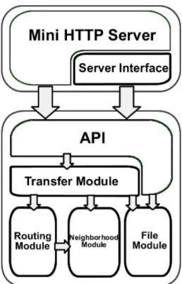
2.4 Content-Centric Networking . . . 17 2.4.1 BitTorrent . . . 18 2.4.2 Opportunistic Networking . . . 19 2.4.3 Social-aware Networking . . . 26 2.5 Conclusion . . . 27 3 System’s Architecture 29 3.1 Overall Overview . . . 29 3.2 Solution Requirements . . . 29 3.3 File Module . . . 31 3.4 Neighborhood Module . . . 35 3.5 Route Module . . . 40 3.6 Transfer Module . . . 44 3.7 API . . . 48
3.8 Mini HTTP Server Module . . . 49
3.9 Log Functionality . . . 53
4 Testing Results 55 4.1 Testing Scenario . . . 55
4.2 Application Parameters . . . 57
4.2.1 Chunk Timeout . . . 57
4.2.2 Download Wait Time . . . 58
4.2.3 Part Size and Chunk Size . . . 58
4.3 Initial Results . . . 58
4.4 Parameters Analysis . . . 60
4.4.2 Download Wait Time . . . 62
4.4.3 Part Size . . . 62
4.4.4 Chunk Size . . . 65
4.5 Tests on New Hardware . . . 66
4.6 UDP Buffer Size . . . 69
4.7 Real Scenario . . . 75
5 Conclusions and Future Work 79 5.1 Main Conclusions . . . 79
2.1 Some examples of Wireless Ad-Hoc Networks . . . 7
2.2 Example of routing discovery, A the initiator and E the destination . . . 11
2.3 Routing zone with ρ=2 . . . 12
2.4 Peer-to-Peer Communication . . . 17
2.5 Haggle Architecture . . . 21
2.6 Example synchronization between a target replica, the photo frame, and a source replica, the laptop . . . 22
2.7 Example Service Tree . . . 24
2.8 Konark Prototype . . . 25
3.1 System’s Architecture . . . 30
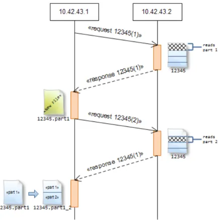
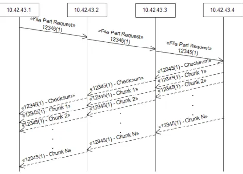
3.2 File part transfer . . . 32
3.3 Writting file parts . . . 34
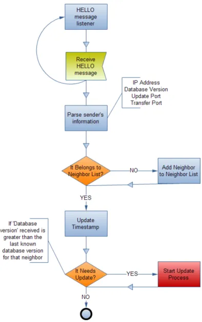
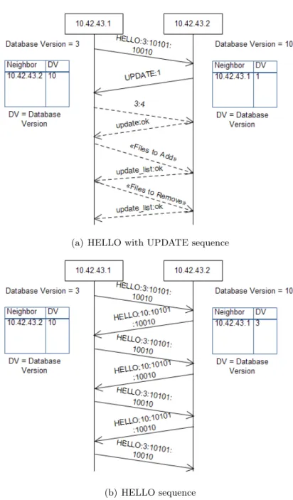
3.4 Receiving HELLO messages . . . 36
3.5 Receiving UPDATE messages . . . 37
3.6 Examples of HELLO interactions . . . 39
3.7 START process . . . 39
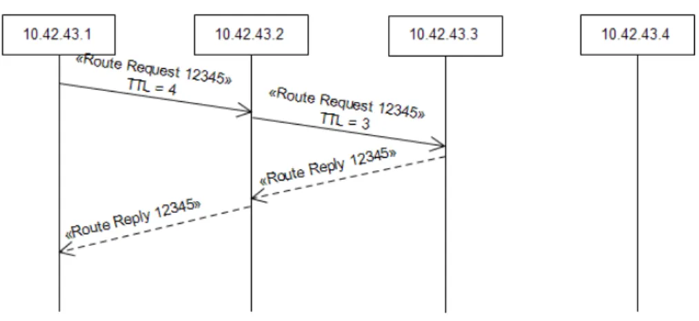
3.8 Requesting Route Example . . . 42
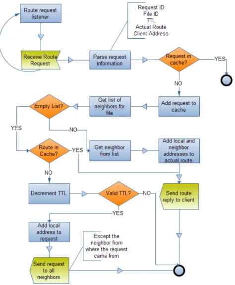
3.9 Receiving Route Requests . . . 43
3.10 Transfer process (Client side) . . . 45
3.11 Transfer process diagram . . . 46
3.12 Getting page index . . . 50
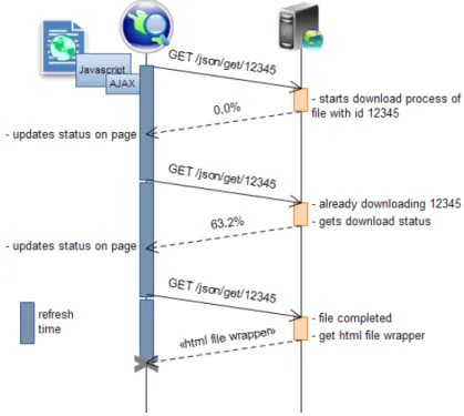
3.13 Downloading file . . . 51
3.14 Accessing file . . . 52 xi
4.1 Network Topology . . . 57
4.2 Routing Results (First Tests) . . . 59
4.3 Transfer Results (First Tests) . . . 59
4.4 Routing Results (Chunk Timeout Comparison) . . . 61
4.5 Transfer Results (Chunk Timeout Comparison) . . . 61
4.6 Transfer Results (Download Wait Time Comparison) . . . 62
4.7 Transfer Results (Part Size Comparison) . . . 63
4.8 Transferring 512KB of data using 512KB file parts . . . 64
4.9 Transferring 512KB of data using 256KB file parts . . . 64
4.10 Transfer Results (Chunk Size Comparison) . . . 65
4.11 Transferring a file part . . . 66
4.12 Hardware Comparison (Chunk Timeout) . . . 67
4.13 Hardware Comparison (Download Wait Time) . . . 67
4.14 Hardware Comparison (Part Size) . . . 68
4.15 Hardware Comparison (Chunk Size) . . . 68
4.16 Buffer Comparison (Chunk Timeout) . . . 71
4.17 Buffer Comparison (Download Wait Time) . . . 72
4.18 Buffer Comparison (Part Size) . . . 72
4.19 Buffer Comparison (Chunk Size) . . . 73
4.20 Transfer of a 128KB file part with 32KB of chunk size . . . 74
4.21 Transfer of a 128KB file part with 16KB of chunk size . . . 74
4.22 Real scenario time results . . . 76
4.23 Real scenario overhead results . . . 77
5.1 A sending error messages to C,D,E when B moves away . . . 81
5.2 Node A transferring a file from B . . . 83
5.3 Network Topology Example . . . 84
5.4 Abstraction layer created by typical routing protocols . . . 84
3.1 Update control codes . . . 38 3.2 API methods . . . 48 3.3 6 bits representing which events are logged with Bytes being the most significant bit . 54
7DS Seven Degrees of Separation ACK Acknowledgement
ADU Application Data Unit
AJAX Asynchronous Javascript and XML AODV Ad-Hoc On-Demand Distance Vector API Application Programming Interface ASP Active Server Pages
ATCP Ad hoc TCP
BBS Bulletin Board System
CORE Common Open Research Emulator CPU Central Processing Unit
CSV Comma-Separated Values
DHCP Dynamic Host Configuration Protocol DNS Domain Name System
DREAM Distance Routing Effect Algorithm for Mobility DSDV Destination-Sequenced Distance Vector
DSR Dynamic Source Routing ECN Explicit Congestion Notification ELFN Explicit Link Failure Notification GPS Global Positioning System
GSM Global System for Mobile communication HTML HyperText Markup Language
IARP IntrA-zone Routing Protocol ICMP Internet Control Message Protocol IERP IntEr-zone Routing Protocol
iMANET Internet Based Mobile Ad Hoc Network InVANET Intelligent Vehicular Ad Hoc Network IP Internet Protocol
JAR Java Archive KB Kilobyte
LAR Location-Aided Routing MAC Media Access Control MANET Mobile Ad Hoc Network MB Megabyte
MFR Most Forward within Radius MID Multiple Declaration Interface MP3 MPEG-1/2 Audio Layer 3 MPR Multipoint Relay
NFP Nearest with Forward Progress OLSR Optimized Link State Routing OS Operating System
OSPF-MDR Open Shortest Path First for Mobile Ad Hoc Networks PDA Personal Digital Assistant
PHP PHP: Hypertext Preprocessor RFN Route Failure Notification
RRN Route Reestablishment Notification RTT Round-Trip Time
SOAP Simple Object Access Protocol TCP Transmission Control Protocol TCP-F TCP-Feedback
TTL Time To Live
UDP User Datagram Protocol URL Uniform Resource Locator UUID Universally Unique Identifier VANET Vehicular Ad Hoc Network
WiMAX Worldwide Interoperability for Microwave Access WSDL Web Service Definition Language
WWW World Wide Web
XML Extensible Markup Language ZRP Zone Routing Protocol
Introduction
Nowadays we are surrounded by mobile devices. Anywhere and in any circumstance, mobile devices are present. Today it is more difficult to find someone in the crowd without any mobile device than the opposite. People are becoming more and more dependent on the information accessible through mobile devices. Besides, devices are becoming more sophisticated which allows you to perform several different tasks anywhere. However, these mobile services are very dependent on some network infrastructure. Many times and in many places, a wireless access point is provided to allow access to all users. When there is no access point available, users can still access the services using WiMAX or 3G. The problem is that these technologies imply costs to users. In case we have content to share on a given event without any network infrastructure available on the event’s location and in case users do not have a 3G plan or the location is not covered with 3G access, then how can users access the content? If devices are able to communicate between each other then no infrastructure is needed.
Ad-Hoc networks allow devices to communicate directly between each other. This way, the net-work relies on each device to route traffic to other devices in order to ensure the communication. We can share content anytime, anywhere, without depending on nothing more than the network devices. Events with a content sharing service may become more frequent as they become more easy to im-plement. There is no time wasted constructing the infrastructure and no costs to acquire or maintain it. Having an infrastructure-less network, we simply need a mechanism to make the contents avail-able. We can either choose an existent solution or create a new one to take advantage of the specific characteristics of the ad-hoc network.
1.1
Objectives
The main objective of this work is to achieve a full functional framework capable of distributing content between devices over an ad-hoc network. The final solution should run on different devices with different operating systems. Besides, the framework should require minimal system configuration or dependencies on additional software. This is important as the framework is designed to deliver content on a spontaneous mobile mesh network. We can assume that on such a spontaneous network, the devices may not have all the dependencies installed and correctly configured. Therefore, we
intend to achieve an off-the-shelf solution in order to successfully work on every single device from the spontaneous network.
We intend to build a framework centered on content, because the ultimate goal is to deliver content on the network. That way, we aim to design the application in a way that the entire network cooperates in order to deliver content between its nodes. This is also known as a content-centric network.
In order to allow users to access the system, a suitable interface should be available. The interface is the ultimate frontier between user and the application. If this interface is not understood by the user, ultimately the application is useless as the user is not able to access it. However, some level of customization should be considered in order to adapt the application to the different needs from different kinds of events.
To allow the system to be used by other applications, allowing any developer to design its own interface and fulfill its own needs, the system must be easily accessible by providing a simple API.
1.2
Methodology
To successfully accomplish the objectives described, the first stage consists on studying the existing applications for ad-hoc networks. In order to understand how the ad-hoc networks work, the different types of ad-hoc networks are studied. We investigate how general applications designed for other scenarios, like wired networks or the Internet, operate over an ad-hoc network without any modification and how the nodes from the network are able to route traffic. TCP is one of the most popular transport protocols used by the most popular applications [3]. Due to that fact, we also study how this protocol performs on ad-hoc networks and how it can be improved to achieve better results. Next, the mechanisms to share content between different nodes on a network are studied. We investigate how applications are designed to share content on an ad-hoc network.
After evaluating the state of the art, we are in better conditions to make our decisions relative to the system design. First, we design the system architecture, defining which modules are going to be implemented and how they interact between each other. For each module, we propose the strategy that seems the most adequate. Next, the implementation process is initiated. The essential system modules are implemented in order to achieve the full functional framework. To ensure that we are able to finish the framework on time, optimizations are delayed in order to have the essential functionalities from each module implemented.
When a functional prototype is ready, some tests must be done in order to evaluate the global performance and to adjust the application in order to achieve the best results. To test the application, a testing scenario must be defined. First some tests are performed with the help of an emulator, which allow us to understand the application behavior. With this knowledge, we can deduce what are the causes for the results obtained and come up with new ideas and improvements to the modules developed in order to increase the global performance. We also need to perform some more tests to discover if the results from the emulated environment are replicated on a real scenario. These real scenario tests are fundamental to observe how the prototype will perform on real events. Since
the main objective is to achieve a functional framework, results from emulated environments are not enough.
1.3
Main Contributions
The main contribution from our work is a fully functional framework for delivering content on-demand. The framework is responsible for delivering content identified by an ID when it is requested. Another contribution is a new routing model based on content that seems best suited to the scenario for which our framework was developed for. Our routing module is responsible for routing files and not addresses. Although, the routing module is very versatile and can be adapted to fulfill other scenarios. We achieved a dynamic interface using HTML produced by a mini HTTP server. The server is able to write the HTML code that is going to be used to provide access to the contents. Besides, we assume that any user familiar with the World Wide Web (WWW) is capable of using our system. This enhances the usability of the system as more users are able to easily use and adapt our application interface.
From the work developed throughout this dissertation, a poster as been submitted and accepted on “11a Conferência sobre Redes de Computadores”, a national conference about computer networks. Conference to be held at the University of Coimbra, Portugal, on November 17-18, 2011.
1.4
Document Structure
The documents starts with an introduction on chapter 1. In order to understand what there is available for content distribution on ad-hoc networks, on chapter 2 we present the state of the art related with ad hoc networks. Chapter 3 presents the system architecture and some implementation decisions. The tests made and the respective results and interpretations are presented on chapter 4. The final remarks regarding the project achievements, conclusions and future work are presented on chapter 5.
State of The Art
Nowadays, most of our devices already communicate using wireless technology. Therefore, we can communicate almost anywhere, at any time, provided that we have a device that supports the wireless technology. It is easy to conclude that this technology is already used by the majority of us, almost every time. We use it when sending a text message with our cell phone, or making a phone call and even in our homes, where we access the Internet through a wireless router.
Although there are many different technologies for wireless communications, such as Bluetooth, Satellite, GSM, among others, this article focuses attention on Wi-Fi (IEEE 802.11). Wireless networks represent today one of the most common means of communication between devices such as computers. Due to their flexibility, these networks have become more interesting compared to the traditionally wired networks. The technology began to be quickly adopted everywhere. When we enter a mall, usually it already provides access to a wireless connection, and also internet access through it to its visitors. One wireless access point in every home, enabling internet access to all the family is also a very common scenario.
Despite its flexibility, there is still a heavy reliance on specific equipment for supporting the com-munication, such as wireless routers. An infrastructure set up at a specific location, allowing access to a wireless connection, represents the most common scenario. This represents a limitation regarding users location, since each user has to position itself within reach of the access point to have connec-tivity. In addition, if there are multiple users concentrated in one place, they will use the same access point, and as a consequence, the access point may become overloaded. The network will eventually become saturated and the quality of communication will degrade. This work focuses on wireless ad-hoc communication which requires no infrastructure to operate, thus allowing communication to be made directly between the various network nodes. Changing the paradigm of connecting to an access point for ad-hoc communication, we can save resources because the infrastructure is no longer needed. The reach of the network will be expanded and resources will be optimized by passing the responsibility of network maintenance from the infrastructure to the nodes that form it. With wireless ad-hoc com-munication, we can resolve problematic scenarios where there is too much people concentrated in one place, each one wanting to access data that is available in one access point or in another node. The access point paradigm cannot handle this scenario, because the node will be overwhelmed with content
requests, and other nodes will simply be out-of-range, unable to contact the access point.
2.1
Wireless Ad-Hoc Networks
A wireless ad-hoc network is a decentralized wireless network [44]. Ad hoc is a Latin expression meaning “for this”, usually meaning a specific solution to a given problem. So, it can be assumed that a wireless ad-hoc network is a special case of a wireless network where there is no network infrastructure. In these networks, the communication shall be ensured by the nodes that comprise it, instead of using routers and access points.
2.1.1 Wireless Mesh Networks
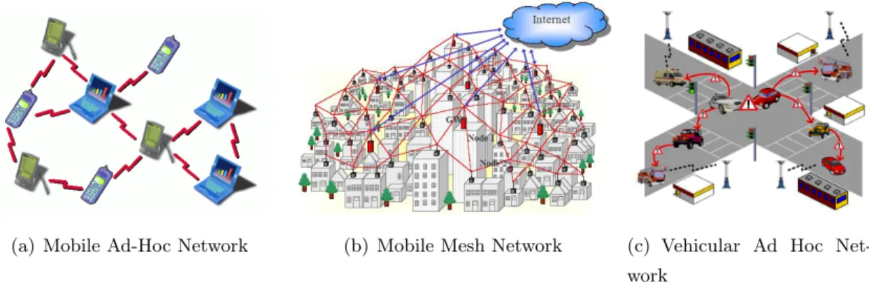
A wireless mesh network is a communications network consisting of multiple wireless nodes, organized in a mesh topology. A mesh topology consists of multiple nodes interconnected, where each node also acts as a router forwarding traffic between the various nodes. An example of such network is represented in Figure 2.1(b). In these networks, each node must be able to choose paths between the various nodes to reach a particular destination. Additionally, it should be able to choose other routes, in case of one or more nodes get disconnected. Typically these networks have a higher reliability and provide redundancy, since there is usually more than one path between a source and destination. In a mesh network, we can have mesh routers which have the job of connecting the various nodes and communicate with other mesh routers. Usually, the mesh routers have more resources compared to other network nodes and accordingly may carry more operations that require resources. These networks, in that point, differ from ad-hoc networks, since some of the nodes have less restrictions in terms of resources. Wireless mesh networks maintain good signal strength, since long distances are divided in a number of intermediate hops shorter. The wireless mesh networks can be of various types [2]:
• Infrastructure Wireless Mesh Networks
• Client Wireless Mesh Networks
• Hybrid Wireless Mesh Networks
An Infrastructure Wireless Mesh Network is very similar to a simple wireless network, where access is based on an access point. The difference is that there is no access point, but several mesh routers interconnected, which makes up the infrastructure for mesh clients. In this type of network, almost all traffic is routed to or from a gateway (router mesh). On the other hand, in Client Wireless Mesh Networks, the traffic flows between arbitrary pairs of nodes, resembling a simple ad-hoc network. The Hybrid is the result of combining the two previous approaches.
(a) Mobile Ad-Hoc Network (b) Mobile Mesh Network (c) Vehicular Ad Hoc Net-work
Figure 2.1: Some examples of Wireless Ad-Hoc Networks
2.1.2 Mobile Ad-Hoc Networks
A mobile ad hoc network (MANET) is a wireless multi-hop network formed by a set of mobile nodes in a self-organizing way without relying on any established infrastructure [7]. These networks are very similar to Wireless Mesh Networks, hence they are also called Mobile Mesh Networks. In these networks, each device can move freely in any direction and thus will change the connections to other devices frequently. The major difference from Wireless Mesh Networks, it is the node’s mobility, as we can see from Figure 2.1(a). To establish communication between different nodes, each one must forward traffic unrelated to itself, thus functioning as a router. The main challenge on building a MANET network is to ensure that each device has, continuously, the information needed to correctly forward traffic. Mobile Ad-Hoc Networks have become increasingly important with the growing number of laptops and Wi-Fi technology. As today there are more and more devices with Wi-Fi that can be transported anywhere, such as PDAs and mobile phones, it is relevant to explore this network architecture because of the potential it represents. Some types of MANETs:
• Vehicular Ad Hoc Networks (VANETs)
• Intelligent Vehicular Ad Hoc Networks (InVANETs)
• Internet Based Mobile Ad Hoc Networks (iMANETs)
The VANETs are used for communication among vehicles and between vehicles and equipment placed on the road as illustrated in Figure 2.1(c). The InVANETs are also VANET networks, but use artificial intelligence in vehicles to act wisely, in case of accidents, in cases of driving under the influence of alcohol, among other situations. iMANET is a MANET network that connects mobile nodes with gateways with access to the internet. An iMANET is therefore quite similar to a wireless mesh network, which in turn, is usually architected as an iMANET.
It can be concluded that wireless ad-hoc networks are quite applicable and cover different scenarios, where a peer-to-peer communication model is needed and there is no infrastructure available.
2.2
Routing Protocols
Some routing mechanism is needed in order to forward data between peers. To accomplish that, there must be some routing protocols to enable communication between nodes from the network that are not in range with each other.
When a node needs to communicate with another node that is not in range, it must forward the packets between intermediate nodes to reach the destination. To route traffic between the nodes, each one has to cooperate to support the communication. The network needs to have a mechanism to find routes between nodes in order to connect sources and destinations. There are too many different protocols to enable routing in Ad Hoc networks. The majority of the protocols can be divided in two categories: proactive routing and reactive on-demand routing [10].
2.2.1 Proactive Routing
The proactive routing protocols focus on building information about the network. The main objective is to maintain an updated table of destinations and respective routes. Due to this fact, this is also known as Table-Driven routing. The tables are updated distributing the routing tables periodically between the nodes. Some proactive routing protocols are now presented and explained in order to understand how the proactive routing protocols work.
Optimized Link State Routing
Optimized Link State Routing (OLSR) protocol is a link-state routing protocol adapted to perform best in mobile ad hoc networks [21]. To gather information about links, the protocol includes a Link Sensing module. This module consist on generating and sending periodic HELLO messages. A Neighbor Detection module is also included that makes use of the Link Sensing module to discover neighbors. Each node is identified by a “main address”, if the node has only one interface, the “main address” is the address of that interface. The protocol is designed in order to identify unequivocally each node. Having more than one interface, the node can be perceived as two different nodes by the neighbors. The node with multiple interfaces uses Multiple Interface Declaration (MID) messages. With this information, the neighbors will correctly identify the node.
The key concept of this protocol is the use of multipoint relays (MPRs). MPR Selection and MPR Signaling modules are responsible of selecting and announce the MPRs. MPRs are responsible for forwarding control traffic to the entire network. The objective of using MPRs is to enable each node A to select a subset of neighbors that will be responsible for retransmitting all the broadcast messages received from A in order to reach all symmetric strict 2-hop neighbors of A.
The protocol includes a Topology Control Message Diffusion module. This module is responsible for the diffusion of messages that contain information needed to enable each node to perform routing calculations. These messages are disseminated throughout the network with the help of the MPRs.
the MPR selection, each node stores information about:
• neighbors • 2-hop neighbors • MPRs
• MPR selectors
The MPR selectors of A are the nodes that selected A as MPR. With this information, each node is able to perform route calculation and to route traffic control messages.
Destination-Sequenced Distance Vector
Destination-Sequenced Distance Vector (DSDV) represents a distributed version of the shortest path problem [35]. Each node maintains a preferred neighbor for each destination. Packet header includes the destination node identifier. When a node receives a packet, it forwards to the destination’s best neighbor. The forwarding process continues until it reaches destination.
To enable the packet forwarding, each node maintains a routing table. The table lists the available destinations and respective hop-number. Each entry includes a sequence number that is generated by the destination node. Nodes transmit information periodically or immediately in case there is new significant information. Besides, they broadcast their routing table. The table may vary often, so it has to be announced frequently.
For each table entry, the destination address, hop-number distance and the sequence number as defined by the destination are broadcasted. When a node receives a routing table broadcast, it forwards it again in a new broadcast after incrementing the hop-number. With the routing information received, each node is able to update its own routing table and identify the best neighbor for each destination. Routes with bigger sequence numbers are preferred on the forwarding decisions, because they represent updated routes. In the presence of two different routes to the same destination with the same sequence number, the one with the lower hop-number is preferred.
A route sequence number is usually generated by the destination. Sometimes the sequence number is changed by other nodes when a link break is detected. To distinguish sequence numbers generated by the destination from the ones generated by other nodes, the destination generates even numbers only while intermediate nodes generate only odd sequence numbers.
When a node A moves to a vicinity of different nodes, it increments the sequence number and sends update messages to its new neighbors. This is done to update the routing tables of the nodes, allowing them to access node A.
This protocol grants each node with a next-hop table for each destination. The next-hop is calcu-lated based on hop-count.
2.2.2 Reactive On-demand Routing
With this type of routing, the route discovery process is issued on-demand. When a node wants to send a packet to another node on the network and does not have a route for it, it initiates a route discovery process. On-demand discovery process generates less overhead for maintaining routes compared with proactive approaches. The overhead generated in order to keep updated routing tables with proactive approaches in mobile scenarios can be very high. The main idea behind reactive routing is that routes must be found and maintained only when they are needed. With proactive routing, routes are discovered and updated constantly even if they are not being used.
Ad-Hoc On-Demand Distance Vector
Ad-Hoc On-Demand Distance Vector (AODV) [34] is an adaptation of DSDV to reduce the number of route broadcasts by creating routes on-demand.
Although being a reactive version of DSDV, some proactive functions remain in this protocol. In order to identify direct neighbors, each node broadcasts frequently HELLO messages. When a node A wants to send a packet to another node that is not its neighbor, it broadcasts a route request message. Upon receiving a route request, if a node B is the destination it responds with a route reply to A. Otherwise, B can respond with a route reply if it knows a fresh route to the destination. When B is not the destination and does not know a route to it, it rebroadcasts the request to its neighbors. Each request packet includes the source, destination, an unique ID and a lifespan value. The lifespan value is used to limit the scope of the request. Each time the request is rebroadcasted, the lifespan is decremented and when it reaches zero, it is discarded. The unique ID is used in order to avoid cycles. When a node receives a new request with the same ID and the same source from a previous request, it is discarded.
Similar to DSDV, each route has a sequence number in order to detect the most recent routes. Besides, each node keeps track of the next-hop for each destination instead of keeping the entire route, just like in DSDV. AODV uses route error messages when link break is detected. These messages are used to announce which nodes are now unreachable. The protocol works only on symmetric links.
Dynamic Source Routing
Dynamic Source Routing (DSR) is a protocol for multi-hop wireless ad hoc networks [22]. This protocol is entirely on-demand. There is no traffic when there is no need for routing packets.
Each packet includes on its header the full path from source to destination, this ensures that the path is loop-free. Intermediate nodes do not need to have updated routes to deliver packets. Since the full path is in the packet header, each intermediate node is able to cache the route.
The protocol assumes that each node chooses only one IP address. Although nodes can have more than one network interface with different addresses, each one has to choose one address to join the DSR protocol.
Figure 2.2: Example of routing discovery, A the initiator and E the destination The protocol is composed by two fundamental modules:
• Route Discovery • Route Maintenance
When there is a route to the destination on the route cache, the source node adds the route to the packet header and sends the message to the next hop. In case there is no route available, route request messages are broadcasted. The request is identified by a unique request id including information about the initiator and the target. Each individual route request contains also a list of addresses of the nodes it passes through. The list is initialized empty by the initiator. When a route request is received, it is checked if a previous request with the same ID was received. If that is true, the request is simply discarded. In Figure 2.2 you can see how the routing discovery works.
The destination can respond to the initiator if already has a route for it. Otherwise, it starts a route discovery to the initiator, but to avoid request cycles, it adds the route reply in the request. With this approach, DSR can operate in the presence of uni-directional links. Another way of sending route replies is to reverse the path on the route request.
When there are packets to send to a destination that has no route yet, they are stored in a Send Buffer. After some time they are discarded.
The route maintenance process is only performed when the source is sending packets. There are no other mechanism to see if the route remains valid, like in proactive protocols. The node detects that a route is invalid when it tries to use it.
To detect route errors, acknowledge packets (ACK) are used between intermediate nodes. For example, node A, sends a packet to E, passing through B,C and D similar to the scenario in Figure 2.2. If node C sends a message to D and does not receive an ACK, it sends a route error to A. Node A removes the route from the route cache and uses another route in cache or issues another route discovery.
2.2.3 Hybrid Routing
In order to take advantage of both proactive and reactive routing, there are some attempts to merge the two different approaches on a hybrid solution. That is the case of Zone Routing Protocol (ZRP) [5]. In ZRP there is a concept of zones. Each node defines a routing zone being ρ the zone radius in
Figure 2.3: Routing zone with ρ=2
hop number. The nodes are classified as interior or peripheral nodes. The peripheral nodes are at distance = ρ.
For nodes within the zone, ZRP uses a proactive IntrA-zone Routing Protocol (IARP). For nodes that do not belong to the zone, it is used a reactive IntEr-zone Routing Protocol (IERP). IERP relies on IARP to perform route discovery and route maintenance. The two different protocols are not specified by ZRP, being the IARP a suitable proactive protocol and IERP a reactive one. IERP uses the information from IARP in order to bordercast the route request. Bordercasting is the term defined in ZRP to the process of sending requests directly to the zone border, i.e. to the peripheral nodes. When a node receives a route request, it replies if it knows the destination or bordercasts the request again. The routing information can be accumulated in the request, like in DSR, or stored as next-hop addresses like in AODV. How the routing information is stored is not defined.
To better understand the zone concept, you can look at Figure 2.3. You can see the zone of node S with ρ=2. All nodes except K are within the zone, because they are at least 2-hops away. When S wants to find a route to K, it will bordercast the route request to nodes G,H,I and J because they are peripheral nodes.
In order to reduce queries traffic, some query-control mechanisms are needed, like query detection and early termination.
Neighbor discovery can be achieved by the MAC layer or using HELLO messages.
2.2.4 Location-aware Routing
Proactive and reactive routing protocols are very tied to the topology of the network. The performance depends on the network topology and due to that fact, as the nodes mobility increases, the worse these algorithms will perform. A different approach to route traffic is to use physical position of the nodes as the base to route traffic between the network. These are called location-aware routing protocols and assume that each node is able of knowing its physical coordinates, using for example a GPS.
Distance Routing Effect Algorithm for Mobility (DREAM)
This protocol uses a Location Table to store information about other nodes location [4]. To accomplish this, each node announces its own location in order to be disseminated throughout the network. This table also includes for each node, the time of the last position update. “The farther two nodes are separated, the less often their location table entries need updating”, this is due to the distance effect, that states that farther nodes appear to move slower than closer nodes. Taking this statement in consideration, two different types of packets are used. Packets have a life time based on the physical distance. Short-lived packets are sent more frequently while long-lived packets are sent less frequently to get farther in the network. The frequency of control messages sent, depends on the nodes mobility. The main idea of DREAM is the use of the location table in order to calculate the direction where the destination node is, so the packet will be broadcasted only to the nodes that are in the direction of the destination.
Location-Aided Routing
Location-Aided Routing (LAR) [24] is a protocol similar to DREAM. LAR defines an expected zone to the destination. If the source has a previous position of the destination then it uses that information to calculate an expected zone. If the source does not know a previous destination’s location, it defines the expected zone as the region that potentially comprises all the ad hoc network. In this case, the algorithm is equivalent to a basic flooding.
Besides, a request zone including the expected zone is defined. Only nodes inside the request zone forward the request. This request zone is defined by the source node. Each node uses the information about the nodes location and expected zone to route the requests only in the direction where the node is expected to be.
The major difference of LAR compared to DREAM is that DREAM uses directed flooding to deliver packets, while LAR only uses directed flooding on the route discovery and maintenance process.
2.2.5 Other Routing Protocols
There is a vast number of different routing protocols. Due to that fact, it is not possible to present all of them, but we have just presented some allowing us to perceive the different approaches to route traffic. The routing protocols presented cover a vast number of similar routing protocols based on the same ideas. Although there are some other routing protocols that worth mention.
In section 2.2.4 on page 12 we present some protocols that are based on physical nodes position. Both DREAM and LAR are protocols that use directed flooding. The principal idea is to flood packets in the direction of the destination. But there are different approaches in location-aware routing.
There are some protocols that are based on the Greedy Forwarding principle. The main idea is to forward the packet to the node that is closest to the destination on each step using only local
information. There are some protocols based on this principle like the Most Forward within Radius (MFR) [42], Nearest with Forward Progress (NFP) [20] and Compass routing [25], each one using a different notion of progress.
In the Location-aware category there is another type of routing known as Hierarchical Routing. The location-aware paradigm is used to route packets on long distances while a proactive distance vector is used when the packet is close to the destination. Grid [27] is an example of hierarchical routing.
In a large network, a vast number of different devices can be present. Due to the heterogeneity of the network, some nodes have more computational and communication capabilities [10]. These nodes are more suitable to support the network functions like routing. Cluster-based routing is based on this principle and it arranges nodes in overlapping clusters. In a cluster there is a clusterhead that is responsible of coordinating the cluster. It supports the routing process for the intra-cluster com-munication. Other nodes of the cluster can communicate directly with the clusterhead and gateways only. Gateways are the nodes that communicate with 2 or more clusterheads and allow inter-cluster communication. Only clusterheads and gateways participate in the propagation of control and update routing messages. This approach reduces the routing overhead and allows the adoption of existing routing protocols.
A simple algorithm to choose the clusterhead, supposing that each device has a unique ID, consists on choosing node with the most lower ID. This way, 2 clusterheads never get in contact with each other.
Every node from a cluster can communicate with the clusterhead, in that way, each node can communicate with every other node of the network with a maximum of 2-hops.
Since traffic concentrates on the clusterhead, a cluster bottleneck may occur when the clusterhead is not able to handle the tasks to support the cluster. This can be resolved by adopting a distributed cluster approach.
When the node’s mobility increases, the formation of new clusters may generate excessive overhead. There is another category of routing protocols that focus on content instead of routing between 2 specific nodes. This paradigm is known as Content-based routing. When we talk about content-based routing we are talking about the publish-subscribe paradigm [8]. Typically the content is simply an event. When a node wants to receive, for example, events regarding the company “Intel” it will create a predicate like [ company = “Intel” ]. This subscription must be done on its neighbors or brokers, registering the intention of receiving content that match the predicate. These nodes are the subscribers. Each node has to subscribe the content that it wishes to receive before it is produced. The publishers are the content producers that submit events in the network. When each broker receives a new event, it already knows where to forward it due to its subscription table. Content-based routing can be used, for example, on a stock market. Users intend to receive events on-the-fly related with specific companies and specific stock values. This represents a good approach to disseminate content when it is constantly being generated.
Typically, content-based routing protocols are designed for static networks. Furthermore, in [43] is proposed an adaptation that mixes content-based routing with peer-to-peer networks.
2.3
TCP on Mobile Ad Hoc Networks
TCP was initially designed to operate on wired networks [10]. In order to understand how TCP per-forms on mobile ad hoc networks, several studies were conducted. In face of multi-hop and mobile scenarios, TCP throughput decreases drastically. Besides, other problems are discovered. The prob-lems are due to intrinsic characteristics of the TCP protocol. In [46, 47] three different probprob-lems were identified:
instability problem The TCP connection throughput can be very unstable, even when it is the only active connection
incompatibility problem In case there are two simultaneous TCP connections, it may happen that they cannot co-exist. When a connection develops the other shuts down.
one-hop unfairness problem With two simultaneous TCP connections, if one is one-hop and the other multi-hop, multi-hop connection is disconnected even if it started first.
Furthermore, the unstable throughput on mobile scenarios can be easily explained by the nature of the TCP protocol. Since the ratio of packets lost in wired networks is very low, TCP interprets packet loss as an indication of network congestion. In TCP, packet loss is interpreted as packets discarded by routers due to congestion. TCP triggers the congestion control mechanism, reducing the transmission windows size and retransmitting the packets. Typically, in ad-hoc networks, the packet loss is due to route failure. Having nodes changing place constantly leads to route failures that are interpreted by TCP as congestion. This leads to unnecessary retransmissions during the route reconstruction, degrading the communication throughput. Besides, the mobility can aggravate the unfairness between concurrent TCP sessions.
In [15] it is demonstrated that there is an optimal value for the size of the congestion window for a given topology and traffic pattern. The problem is that TCP operates with a much higher value resulting in low throughput.
According to [3], less attention has been devoted to UDP applications, due to the fact that the most popular applications use TCP. Besides, the interaction between 802.11 MAC protocol with TCP protocol may lead to unexpected phenomena in a multi-hop environment, like severe unfairness prob-lems in simultaneous TCP flows and in extreme cases, channel capture by few flows. It is stated that these phenomena do not appear when UDP is used, or appear with less intensity.
2.3.1 TCP-Feedback
TCP-Feedback (TCP-F) is a scheme defined in [9]. This is a scheme that tries to introduce a feedback system to the TCP. The key idea is to use Route Failure Notification (RFN) messages to alert the
TCP sender when a route fails, preventing the congestion control mechanism from being triggered. This allows the distinction from route failure and real network congestion.
When a node detects a route disruption due to the mobility of the next-hop, it explicitly sends a RFN message to the TCP sender. Upon the reception of a RFN message, a intermediate node invalidates the route, preventing traffic from being forwarded further. If the intermediate node knows an alternative route, it uses that new route discarding the RFN message. Otherwise the RFN is propagated toward the source.
As soon as the RFN message arrives to the sender, it goes into a snooze state. The sender stops completely from sending packets (new or retransmissions). Marks all timers as invalid and freezes the window of packet sending. Besides, other variables are frozen like windows size or retransmission timeout. A route failure timer is started with the time for the worst case of route reestablishment. The sender keeps in snooze state until a Route Reestablishment Notification (RRN) is received.
After a RRN is received the communication is resumed using the same rate used before route failure. The main idea from this scheme is to freeze the sender, disabling TCP from issuing the congestion control mechanism.
2.3.2 ATCP
ATCP (ad hoc TCP) [28] is a layer for ad hoc TCP. The authors decided to keep TCP protocol intact and implement a new layer between IP and TCP. When the network is partitioned, the TCP sender is put on persist mode, stopping transmitting data, similar to the snooze state from TCP-F. In case packets are lost due to error, TCP sender retransmits without firing the congestion mechanism. If the network is in fact congested, TCP sender invokes the congestion control mechanism normally.
ATCP achieves this functionality by listening to network state information. It uses Explicit Con-gestion Notification (ECN) [37] and ICMP “destination unreachable” to interpret what is happening in the network and perform the proper actions. When ICMP “destination unreachable” messages are received, the sender is put in persist mode. The ECN messages are used to invoke the congestion control mechanism immediately instead of waiting for timeout.
In order to detect if there is a new route already, some probe packets are sent while in persist mode. When ACKs are received for these probe packets, the sender is put on normal mode.
Being the ATCP layer transparent to TCP, ATCP and non-ATCP nodes can inter-operate. Al-though the non-ATCP nodes will suffer from the problems of using TCP on mobile ad hoc networks.
2.3.3 Explicit Link Failure Notification
Explicit Link Failure Notification (ELFN) [19] is a mechanism similar to the previous works already presented. The route error messages from DSR were modified in order to carry a payload similar to ICMP “destination unreachable” messages. This extra information contains pertinent fields from the TCP/IP headers of the packet that instigated the notice, including the sender and receiver addresses.
Figure 2.4: Peer-to-Peer Communication
The process when a ELFN packet is received is similar to the ATCP process when a ICMP “desti-nation unreachable” is received. The sender enters in a standby mode and disables its retransmissions timers. To get into a normal state, a probe packet is periodically sent, just like in ATCP.
2.4
Content-Centric Networking
Instead of referring a specific location of the data that we are interested in, maybe it is a better approach to focus on the data we need. That’s what content-centric networks are all about. We no longer need to know the specific location of the things we want to access and therefore, the data is made available without a specific absolute reference. With this approach, the data may be available in more than one location at a time, creating therefore a whole bunch of new scenarios that can be explored.
One architecture that fits the content-centric definition is peer-to-peer. Peer-to-peer is an architec-ture of distributed systems, where each node performs either server and client operations [40]. So the functions in the network become decentralized, unlike the usual paradigm of client-server, where we have multiple clients accessing a server. In peer-to-peer networks, we have multiple clients connecting with each other, i.e. any node can perform the functions of both server and client, in case it is serving or requesting another node. For example, in Figure 2.4, node B is a client of node C and at the same time is serving node A, performing server operations. Peer-to-peer makes possible the creation of larger and more reliable networks than other architectures, since there is no dependence on servers, avoiding single points of failure and network saturation as the number of users increases.
Nowadays, there are several peer-to-peer networks already, such as Kademlia [29], BitTorrent [12] among others. Although these systems are widely used today and allow decentralization of communi-cations, these were designed based on Internet protocols and domain, assuming that there is a direct end-to-end connection. In turn, in ad-hoc networks, it cannot be assumed such a thing, since it is not always possible to have a direct connection between two nodes, implying routing of messages by intermediate nodes.
2.4.1 BitTorrent
BitTorrent is a peer-to-peer file sharing protocol. BitTorrent is one of the most used protocol for transferring big files and it is estimated to be the protocol that generates more traffic in all Internet [18]. With BitTorrent, we can distribute files without the need of a single source. Thus, when we want to distribute a file, we can just join the swarm and eventually the file will be available at all nodes interested in it. The biggest difference between this protocol and other file transfer protocols, is the way how data is delivered. In BitTorrent, the data is delivered by passing file parts between peers, as the number of peers rise, the more bandwidth will be available for the transfer.
For a user to upload a file, first thing to do is to create a torrent descriptor file. After that, the file must be sent by any conventional means, like web or email, to interested users. Then, the user makes the file available through a BitTorrent node that will act as a seed. Those who want to grab the file, just need to give the torrent file to their own BitTorrent nodes which will act as peer or leecher to download the file by connecting to seeds or other peers. When a peer finishes downloading the file, it becomes a seed.
The file is divided into segments called “pieces”. When a peer receives a new piece, it becomes a source of that piece. Thus, a peer can download pieces from seeds or from peers that already have them. Seeds do not need to send all pieces to all peers, because they will be disseminated between them. The torrent descriptor file contains a cryptographic hash of every piece to prevent malicious modifications to pieces passed between peers [13]. With this approach, the distribution of files is shared by the peers who are interested in them.
The torrent file contains metadata relative to the files being shared. It contains also “tracker” related metadata. The tracker is the node that will inform about other nodes in the network from which the peer can download file pieces. So, when a user wants to access a file, first he has to have access to its torrent and pass it to his BitTorrent client that should contact the tracker to obtain the list of peers and seeds, connecting to them to download the file.
Although being one of the Internet’s most efficient content distribution protocols, BitTorrent is not best suited for wireless ad-hoc networks, because of its nature. In a wireless ad-hoc network, a peer is both router and end-user. For that fact, to enable end-to-end communication, sometimes we need that intermediate peers act as routers, forwarding the traffic in the network. Beyond that, TCP performance drops seriously with the number of hops. We can extrapolate that the BitTorrent ’s overlay, when mapped in a wireless ad-hoc network, it does not produce the best results. Being both BitTorrent and Wireless Ad-Hoc Networks, based on Peer-to-Peer paradigm, it seems appropriate to try to combine both concepts. In that sense, there are some investigation in how to change and adapt BitTorrent to these networks.
BitHoc is an enhanced variant of BitTorrent tuned to ad hoc networks [39]. BitTorrent is topology unaware by default. The TCP connections to the neighbors in the network, are established inde-pendently of their location. Thus leading to slow TCP connections due to long multi-hop paths and routing overhead. The first solution was to limit the scope of the neighborhood conducting to shorter
download times, but on the other hand, it leads to bad sharing ratios. BitHoc modifies the chocking algorithm and adds a new piece selection strategy. Now, the lookup process is no longer granted by a tracker as in the original BitTorrent protocol. In BitHoc, a peer wishing to find other peers in the network starts by sending HELLO messages with a certain TTL, creating a table of peers based on the responses. Then, peers are categorized as nearby or far peers, as they are up to 2 hops away or not. The idea is to concentrate the traffic in nearby peers, for example, the piece update message is only sent to nearby peers. Furthermore, a peer elects 3 best uploaders and constantly connects with them to allow a more quickly transfer. One fourth neighbor is chosen in a random way to increase diversity of pieces in the network. Besides that, there is a configurable parameter q, representing the ratio between nearby and far neighbors that the peer will serve on that fourth neighbor. When connecting to far neighbors, the piece selection follows the absent piece stategy, only pieces that are not in nearby neighbors are accepted. The piece selection in near nodes follows the local rarest first as the BitTorrent’s standard. Although, BitHoc does not take in consideration users mobility.
In [36] the authors compare two different adaptations of BitTorrent over MANETs: BTI and BTM. BTI is a straightforward implementation of BitTorrent in MANETs while BTM is a cross-layer adaptation of BitTorrent for MANETs. In BTI, there are some adaptations made to the original BitTorrent. Both the tracker and seeds can respond to a torrent seeker with the torrent file. The lookup is made with the broadcast of TREQ messages and when a TREP is received, the node contacts the tracker and it gets the node list and connects to all nodes listed. Then, the client connects with server peers and starts downloading pieces that it does not already have. The unreceived pieces are delivered in a random way. When a client finishes downloading of π will decide to seed a file with probability ρπs for a duration tπs. When the download is completed, if the node decides to seed based on ρπs, then it sends a SEED message to the tracker. When the time tπs is elapsed, the node sends a UNSEED message to the tracker. One of the major differences is that BTM gathers information on the network, taking advantage of the routing layer. When a new torrent is created, it is broadcasted to neighbors that will re-broadcast it with a given probability. Information from broadcasts is stored locally at every node’s cache. There is no tracker to a given torrent, so each node has to find peers by itself. If the information about torrents and/or peers is not present in the local cache, then it is used the same method like in BTI, using TREQ and PREQ messages. These TREQ and PREQ messages are also used to build a local cache at the nodes that receives them. Another big difference is the use of proxy seeds. Typically, one torrent starts with one seed and due to the nature of MANETs, the file may become inaccessible. To fix that problem, during the torrent broadcast phase, nodes which satisfy a given hash function become proxy seeds. Proxy seeds immediately connect to the initial seed and download the file, becoming seeds to that file. This ensures that there are many copies of the file in several sections of the network. At the end, authors conclude that BTM outperforms BTI in terms of performance.
2.4.2 Opportunistic Networking
In opportunistic networking no assumption is made with regard to the existence of a complete path between two nodes wishing to communicate [33]. Thus, the paradigm surrounding mobile ad hoc
networks is changed, because we no longer need to concentrate our efforts on building knowledge about the network topology. The communication is achieved by opportunistically passing data to nearby nodes as they are within reach.
In this section we present an architecture and some frameworks and middlewares designed for opportunistic networks. The architecture represents only the concept, the design of a possible system that can be adopted. A framework is a software that incorporates several functionalities in order to be used by another software to ease the design process. Various parts of the framework may be exposed through an API. A middleware is a fully functional software, operating independently, providing services to people or other applications.
An Architecture
In [41] is presented a network architecture called Haggle, designed around mobile users. Nowadays, when we want to share a file with a friend or a colleague, even if both have wireless compatible devices, most often we will just use a USB key flash drive, as pointed out by the authors, representing a Pocket Switched Networking scenario. Haggle is composed by the following modules as shown in Figure 2.5:
• User Data
• Delivery (Names) • Protocols
• Resource Management
Now, an application running on top of a Haggle system, does not need to include network protocol functionality on its implementation. The delivery process is made using user-level names, instead of protocol specific addresses, like IP addresses. Besides that, a resource management module is included to calculate cost-benefit for a given task.
User data in Haggle is represented through Application Data Units (ADUs). ADUs are an encap-sulation for a data item respecting to an application like a music file, a photo, a message, etc. ADUs are then sent to and from applications and also to and from other Haggle nodes. Normally, some user data is linked together to form complex data, like for example, a website with embedded images. Therefore, ADUs can be linked together using a claim attribute.
Haggle stores forwarding state in ADUs, taking advantage of their flexibility to be modified, adding or removing fields. Forwarding ADUs can contain information like a list of destination names and addressing hints to each destination, a list of nodes that has passed through, security information and some other relevant information. ADU’s destinations are expressed using names. For each name it is checked if there is some protocol available in Protocol module, able to deliver the message. Associated to a name, there could be several protocols, like Bluetooth, 802.11, among others. Furthermore, ADUs can contain mappings to addresses, like emails, Bluetooth MAC addresses, telephone numbers, allowing the use of several different protocols from different applications.
Figure 2.5: Haggle Architecture
To take advantage of connection opportunities, Haggle must perform neighbor discovery. One example of that, it is a Bluetooth inquiry resulting in a set of Bluetooth MAC addresses being marked as “nearby”. When internet access is available through an access point, all internet domains are marked as “nearby” too. Therefore, forwarding algorithms estimate the “benefit” of transferring a given ADU (or set of linked ADUs) to decide if the ADU is forwarded in that direction or not.
The resource management module is responsible for controlling all use of resources in Haggle. This module performs a cost/benefit analysis on “tasks” specified by the other modules to decide what action to take next.
With Haggle, applications can exploit all types of data transfer without specifying code for each circumstance. Besides that, network endpoints can be specified by name schemes instead of specific network addresses. The resources are used efficiently by mobile devices by allowing users to prioritize their tasks.
Besides this architecture, it is found in the literature some other works that focus attention on the practical implementation surrounding opportunistic contacts between nodes. That is the case of both 7DS [30] and Cimbiosys [38] frameworks described below.
Frameworks
In [30], authors introduce two new applications to their earlier work, File Sharing and Synchronization and News Sharing in a Bulletin Board System (BBS). To create these applications, 7DS has a Discovery Module that is built on top of mDNS protocol. It enables the creation of an IP network automatically. For that to be possible, Apple Bonjour1 is used. Apple Bonjour enables automatic discovery of computers, devices and services on IP networks without the need of DHCP, DNS or directory servers. To take advantage of that system, every information is treated as a service, thus being discovered and delivered easily.
For a user to share content, it starts by defining a shared directory in which all shared objects are placed. The version controller scans the directory to find insertions or deletions to register all
1
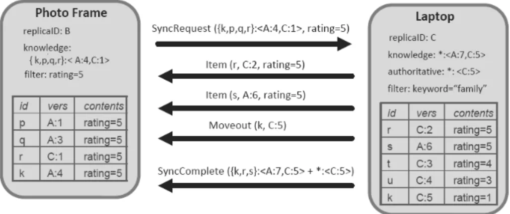
Figure 2.6: Example synchronization between a target replica, the photo frame, and a source replica, the laptop
modifications. To detect modifications, it is used the JNotify2 library. Afterwards, version controller multicasts tuples of hash values and modification dates of each file, using the discovery module, reflecting the changes made. Missing or outdated files are reconciled automatically, the synchronization is transparent to user, being the synchronization request issued by the file-sync module. For the synchronization process, it is used 7DSRsync, an adaptation of Rsync to 7DS. Unlike file-sync module, the BBS module does not exchange data automatically and transparently to the application. Metadata is exchanged when new mobile users are discovered, based on the category and type of the information, the user issues a download request.
Cimbiosys [38] is a framework for content-based partial replication. The major difference to 7DS File Sharing is that now, the content is filtered locally, so the replication is only partial. Partial-replication implies new challenges compared to total-Partial-replication regarding filter consistency among others. Besides that, some other challenges emerge with this scenario. Authors define 5 key challenges:
effective connectivity ensuring a path between peers for every item
partial synchronization allowing incremental synchronization without wasting bandwidth with du-plicate items or metadata overhead
item move-outs informing devices of items that no longer applies to their filter due to recent updates out-of-filter updates dealing with updates that do not match the updating device’s own filter filter changes allowing a device to change its filter
The system model is designed taking in consideration the challenges presented. Cimbiosys grants two important system properties: eventual filter consistency and eventual knowledge singularity. The first one states that “Each device eventually stores precisely those items that would be returned by running its custom filter query against the full data collection”, that is an important property to ensure consistency. “The state that is transmitted between devices in synchronization requests and is used to identify unknown latest versions converges to a size that is proportional to the number of replicas in
2
the system rather than the number of stored items.”, the second property grants a more economical use of bandwidth and system resources. The data replication is based on collections, each collection is composed by items. Each collection has its own access control policy that defines which operations are allowed. A replica contains copies of all or some items of a collection and each device can have various replicas of different collections. A device sharing a collection, keeps its own replica of items. Each item is composed by a unique id, a version id, a XML and the respective file contents and a deleted bit. Besides that, it can have additional information to deal with merging conflicts. The version id is composed with the replica id and the update count number. The XML contains information respecting to item’s file. When a item is deleted it is marked as deleted using the deleted bit.
Each replica has a filter to determine the contents to be stored locally. To ensure security, versions are digitally signed by the originator and policies are used to define create/update/delete properties applied to devices. The synchronization is pull-based. Each device wishing to synchronize its content contacts other replica to perform the synchronization. To ensure consistency between replicas, each replica keeps a version vector representing versions that it knows, and this vector represents an element key in the synchronization process. For a better understanding of the synchronization process, we can look at Figure 2.6. We can see a synchronization issued from replica B to replica C. In this particular case, replica B is only interested in items with rating equal to 5. In this synchronization process, item r is updated since there is a new version C:2, while the version in B is C:1. The s item is added, since it matches filter of replica B. Item k is removed from B since it is tagged with rating=1 on the newest version.
The Item Store is where all items are stored. Only the most recent known versions are stored. Besides the Item Store, each node has a Push-Out Store to keep files that are out-of-filter after an update. For example, if in a replica that filters only items tagged as “public”, an item A is changed from “public” to “private”, it must be stored temporarily before being discarded to ensure that the update is propagated. One of the implementations has been made in C# using Microsoft .NET Framework running on Windows. Another version was implemented in Mace [23]. Cimbiosys exports an API that enables an application to create a collection, create a local replica, add, update or delete items, run queries over items, initiate a synchronization, establish synchronization partnerships, change access permissions and change local filter. In terms of communication, Cimbiosys offers a variety of transport protocols.
Middlewares
There are various middlewares specially designed to operate in ad hoc networks. Konark is a middle-ware designed specifically for discover and delivery of device independent services in ad-hoc networks [16]. Konark allows the announcement and discovery of services in the network, thus each node can act as server and client. Konark has two main parts, Service Discovery and Service Delivery. For this to be possible, each device includes a Konark Application to facilitate the human interaction with the system and it also includes SDP Managers and Registry that are responsible for maintain service objects and information about services available in the network. Besides that, a micro-HTTP server is