Multiple Input Multiple Output System with Multi User Support
Based on Directive Information Transmission
Paulo Carvalho1, 2, 3, Mario Marques da Silva2, 4, and Rui Dinis1, 2 1DEE, FCT Universidade Nova de Lisboa, Portugal
2IT, Instituto de Telecomunica¸c˜oes, Av. Rovisco Pais, Lisboa, Portugal 3Uninova, Instituto de Desenvolvimento de Novas Tecnologias
Quinta da Torre, Caparica, Portugal
4Universidade Autonoma de Lisboa, Portugal
Abstract—Low interference and privacy are crucial requirements for system reliability and se-curity. Present and further mobile communication systems must support multiple users achieving at same time low interference levels. Several solutions can be adopted to reduce interference be-tween users, such as spreading codes or beam forming. For very high bit rates first solution must be discarded. On the other hand, in environments with a very high number of users beamforming can impose demanding hardware requirements in mobile devices, which is undesirable. Transmit-ters with directivity introduced at information level where the transmitted constellation is only optimized in the desired direction can also be used to assure low interference. Under this ap-proach, power efficiency on amplification can be also improved, due to the fact that constellations are decomposed into several BPSK (Bi Phase Shift Keying) or QPSK components (Quadri-Phase Shift Keying), being each one separately amplified and transmitted independently by an antenna. Therefore, several users can coexist since each user must know the configuration parameters asso-ciated to the constellation configuration, i.e., the direction in which the constellation is optimized, otherwise receives a degenerated constellation with useless data. The simulation results show the effectiveness in user data stream separation of the proposed approach.
1. INTRODUCTION
Performance of wireless communication systems can be compromised by interference. Normally, interference among users is minimized by orthogonalizing the channel so that the BS (base station) communicates with each user in separate time-frequency resources. This reduces overall efficiency and throughput and higher data rates can only be achieved when the BS communicates with several users using same time-frequency resource [1, 2].
MIMO (Multiple-input multiple-output) systems can increase throughput in modern wireless networks and reduce interference [3–5]. One advantage of MIMO systems is the reduction of the transmitted power. On the other hand, the use of multilevel modulations in modern wireless stan-dards leads to high peak-to-average power ratios and further drives the costs of power amplifiers while reducing their efficiency. This problem can be avoided with this new transmission scheme, where the constellations are decomposed into several BPSK, QPSK or OQPSK components (Offset QPSK), being each component amplified and transmitted independently by an antenna. Further-more, power efficiency can be also improved adopting nonlinear (NL) amplifiers in such operation, which can maximize the power efficiency of the transmission system [6, 7]. Now the coefficients associated to each array element are the coefficients associated to the elementary sub-constellations and each antenna transmits uncorrelated signals. Obviously, in the desired direction of transmission we have the optimized multilevel constellation, otherwise the constellation signal is degenerated. Since the directivity is introduced in the transmitted information, this can be viewed as a scheme where the directivity is implicitly on the constellation’s symbols arrangement associated to each transmission direction.
Current MIMO transmitters require a separate RF (Radio frequency) — chain including a power amplifier for each antenna element [8]. Therefore, the transmission scheme resembles to MIMO transmitter structures, since we still have several RF-chains in parallel. However there is a key difference in the concept since each RF chain is associated to a BPSK component of the multilevel constellation that is transmitted. Obviously, the receiver must know the constellation coefficients, associated to the amplification stage as well as the array configuration, otherwise will receive a degenerated signal. Therefore, interference among users can be avoided when the transmissions are only optimized for the directions θj associated to the several users.
SC-FDE schemes (Single-Carrier with Frequency-Domain Equalization) [9] are excellent trans-mission schemes for broadband wireless systems, with low cost transmitters and efficient power amplification when constant or quasi constant envelope modulations are employed. Another draw-back of multilevel constellations is their sensitivity to imperfect channel compensation effects (par-ticulary when we have a linear equalizer optimized under the MMSE (Minimum Squared Mean Error)). Additional performance improvements can be achieved by a IB-DFE receiver (Iterative Block Decision Feedback Equalization) [9–11], where both the feedforward and the feedback filters are implemented in the frequency domain. Obviously, IB-DFE receivers should be optimized for multilevel constellations to minimize the residual ISI and IQI (In phase Quadrature Interference) interferences associated to multilevel Offset modulations [12, 13].
This paper is organized as follows: A brief characterization of the theoretical principles behind the structure of the transmitter with directivity at constellation level is made in Section 2. Section 3 characterizes the receivers. A set of performance results is presented in Section 4. Section 5 resumes this paper.
2. CONSTELLATION DECOMPOSITION
Let us consider two OQPSK signals, xp(t) and xp0(t), with complex envelope given by
xp(t) =X n0 b(p)n0 x(p)(t − n0T ), (1) and xp0(t) = X n0 b(pn00)x(p 0) (t − n0T ). (2)
Without loss of generality, we assume the same pulse shape for both signals, i.e., x(p)(t) = k
pr(t) and x(p0)
(t) = kp0r(t), where r(t) represents a pulse shape that guarantees null ISI at the matched filter’s output and kp and kp0 are real coefficients. Combining the signals results for each sampling instant
kpb(p)n0 + kp0b(p 0)
n0 = s0n0, (3)
where s0
ncan assume the values ±kp± kp0, ±jkp± kp0, ±kp± jkp0 and ±jkp± jkp0, which correspond to the four sub-sets of 4 symbols from a 16-OQAM (Offset Quadrature Amplitude Modulation) constellation.
Since OQPSK or QPSK constellations are a sum of two BPSK components in quadrature, it turns obvious that the symbols of multilevel constellations can be expressed as function of the corresponding bits as follows1:
sn= g0+ g1b(1)n + g2b(2)n + g3b(1)n b(2)n + g4b(3)n + . . . = M −1X i=0 gi µ Y m=1 ³ b(m)n ´γ m,i = M −1X i=0 gibeq(m)n , (4) with beq(m)n = µ Q m=1
(b(m)n )γm,i. For each sn ∈ S, where (γµ,iγµ−1,i . . . γ2,iγ1,i) is the binary repre-sentation of i and b(m)n = 2βn(m)− 1 where βn(m) denotes the mth bit of the n constellation point. Since we have M constellation symbols in S and M complex coefficients gi, (4) is a system of M equations that can be used to obtain the coefficients gi, i = 0, 1, . . . , µ − 1.
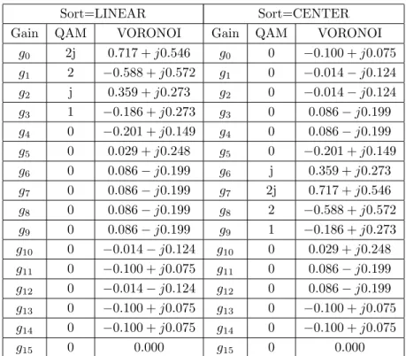
Since power-efficient constellations have zero mean, g0 = 0 and are only necessary M − 1 BPSK signals to generate a given constellation. Moreover, M-QAM constellation’s symbols can be characterized with only log2(M ) BPSK signals, with all the remaining gi coefficients null. For instance, the 16-OQAM with Gray mapping only needs four BPSK signals (associated to the set of non-zero complex coefficients g2 = 2j, g3 = j, g8 = 2 and g12 = 1) or two QPSK or OQPSK constellations.
Let us to use (4) to describe the transmitted signal x(t) as
x(t) = N −1X n=0 M −1X m=0 gibeq(m)n r(t − nT ). (5)
This means that any M-OQAM constellation can be decomposed as the sum of several components with quasi-constant or constant envelope, that can be separately amplified with an non-linear amplifier. The transmitter will have in parallel M RF branches, each one with a NL amplifier followed by an antenna, that transmit the M BPSK uncorrelated signals (i.e., the components of multilevel constellation), as shown in Figure 1. It is also assumed that each succeeding element has a αi = 2πi cos(π
2 + Θ)λd has a progressive phase of the supply current relative to the previous element. We have equal spaced isotropic antennas with d/λ = 1/4 (it should be noted that the current magnitudes at different antennas depend on the amplification coefficients associated to the constellation decomposition). Obviously the BPSK components in the amplification branches are uncorrelated, which means that the resulting radiation pattern is still omnidirectional. Therefore, the directivity is only introduced at the transmitted information through a rearrangement of the constellation symbols according to the direction θ. It is possible to define an equivalent Array Factor (AF) GA as GA= M X i=1 giexp (jαi) , (6)
From (6) it becomes obvious that each sub-constellation suffers a different rotation that depends on the antenna position in the array. By changing the phase of each RF branch, αi, the directivity
Figure 1: Structure of constellation directive transmitter. Table 1: Gain values for Sort=LINEAR.
Sort=LINEAR Sort=CENTER
Gain QAM VORONOI Gain QAM VORONOI
g0 2j 0.717 + j0.546 g0 0 −0.100 + j0.075 g1 2 −0.588 + j0.572 g1 0 −0.014 − j0.124 g2 j 0.359 + j0.273 g2 0 −0.014 − j0.124 g3 1 −0.186 + j0.273 g3 0 0.086 − j0.199 g4 0 −0.201 + j0.149 g4 0 0.086 − j0.199 g5 0 0.029 + j0.248 g5 0 −0.201 + j0.149 g6 0 0.086 − j0.199 g6 j 0.359 + j0.273 g7 0 0.086 − j0.199 g7 2j 0.717 + j0.546 g8 0 0.086 − j0.199 g8 2 −0.588 + j0.572 g9 0 0.086 − j0.199 g9 1 −0.186 + j0.273 g10 0 −0.014 − j0.124 g10 0 0.029 + j0.248 g11 0 −0.100 + j0.075 g11 0 0.086 − j0.199 g12 0 −0.014 − j0.124 g12 0 0.086 − j0.199 g13 0 −0.100 + j0.075 g13 0 −0.100 + j0.075 g14 0 −0.100 + j0.075 g14 0 −0.100 + j0.075 g15 0 0.000 g15 0 0.000
can be increased and the constellation can be optimized for the desired direction. This leads to a directivity in the transmitted information since the constellation will be only optimized in the desired direction. It should be mentioned that there isn’t a fixed arrangement of the several BPSK components in the transmitter. However, here we consider two possible arrangements for the BPSK components of 16 QAM and 16-Voronoi constellations whose sort order along the RF branches are presented in Table 1. The transmitter’s structure is similar to the MIMO’s structure where M uncorrelated data streams for M users are sent at same time. However, here the bit rate do not increases by a factor of M , since the signals from the different branches are components of the multilevel constellation transmitted to a user.
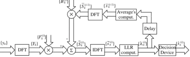
{yn} DFT {Yk} × {Fk (i)}
IDFT DecisionDevice {n(i)} {s~n(i)} {Sk (i) } ~ × {sn(i-1)} {Sk(i-1)} {Bk(i)} + -Delay Average's comput. DFT LLR comput. _ _ { n(i)} Σ λ s^
Figure 2: IB-DFE receiver with soft decisions.
3. RECEIVER
At receiver’s side we may have a similar structure with M antennas in parallel, followed by a combiner that reconstructs the transmitted constellation symbol. Obviously at each branch the coefficients compensate the phase rotation due to channel’s delay and the phase rotations associated to the array configuration of the transmitter. The combiner is followed by a IB-DFE receiver whose structure is depicted in Figure 2. We assume an ideal linear transmitter (this can be achieved with the transmitter structure of Figure 1, with constant envelope signals in each amplification branch). The signal associated to a given block is
s(t) =
N −1X n=−NG
snhT(t − nTS), (7)
with TS denoting the symbol duration, NG denoting the number of samples at the cyclic prefix,
N denoting the number of samples at the useful part of the block and hT(t) denoting the adopted pulse shape. The nth transmitted symbol2 s
nbelongs to a given size-M constellation S. As usual, the cyclic prefix corresponds to a periodic extension of the useful part of the block, i.e., s−n= sN −n with a length higher than the overall channel impulse response.
At the receiver the samples associated to the cyclic prefix are discarded, which means null IBI (Inter Block Interference) and reduces the impact of a time-dispersive channel to a scaling factor for each frequency. Thus, the corresponding frequency-domain block is {Yk; k = 0, 1, . . . , N − 1} = DFT {yn; n = 0, 1, . . . , N − 1}), where
Yk= SkHk+ Nk, (8) with Hk denoting the channel frequency response for the kth subcarrier and Nk the corresponding channel noise.
For a given iteration the output samples are given by ˜
Sk = FkYk− BkS¯k, (9) where {Fk; k = 0, 1, . . . , N − 1} and {Bk; k = 0, 1, . . . , N − 1} denote the feedforward and the feedback coefficients, respectively, and { ¯Sk; k = 0, 1, . . . , N − 1} is the DFT of the block {¯sn;
n = 0, 1, . . . , N − 1}, with ¯sn denoting the average value of sn conditioned to the FDE output associated to the previous iteration. It can be shown that the optimum coefficients Fk and Bk are given by (see [14, 15])
Fk=
κH◦ k
E[|Nk|2]/E[|Sk|2] + (1 − ρ2)|Hk|2, (10) 2It should be pointed out that we have a slight abuse of notation, since in this section s
n designates the nth transmitted
and
Bk = FkHk− 1, (11) respectively, with κ selected to ensure that PN −1k=0 FkHk/N = 1. The correlation coefficient ρ [15],
is given by ρ = E[ˆsns◦n] E[|sn|2] = PM −1 i=0 |gi|2 Qµ m=1 ³ ρ(m)n ´γm,i PM −1 i=0 |gi|2 , (12) where ρ(m)n = | tanh(λ (m) n
2 )| represents the reliability of the mth bit of the nth transmitted symbol.
λ(m)n is the log-likelihood ratio of the mth bit for the nth transmitted symbol given by
λ(m)n = log P s∈Ψ(m) 1 exp ³ −|˜sn−s|2 2σ2 ´ P s∈Ψ(m) 0 exp ³ −|˜sn−s|2 2σ2 ´ , (13)
where Ψ(m)1 and Ψ(m)0 are the constellation’s subsets associated to the symbols with the m(th) bit at 1 or 0, respectively. {˜sn; n = 0, 1, . . . , N − 1} denotes the IDFT of { ˜Sk; k = 0, 1, . . . , N − 1}, i.e., the ˜snare the time-domain samples at the FDE output. In (13) σ2 denotes the variance of the noise at the FDE output, i.e.,
σ2 ≈ 1 2N N −1X n=0 E h |ˆsn− ˜sn|2 i , (14)
where ˆsn denotes the hard decisions associated to sn.
Since we have uncorrelated BPSK components, according to [15] we may write ¯ sn= M −1X i=0 gi µ Y m=1 à tanh à λ(m)n 2 !!γm,i . (15) 4. PERFORMANCE RESULTS
In simulations we considered a SC-FDE modulation with blocks of N = 256 useful symbols plus a cyclic prefix of 32 symbols longer than overall delay spread of the channel. The modulation symbols belong to a M-QAM or M-Voronoi constellation (dimensions of M = 16 and M = 64 are considered) and the transmitted data is mapped on constellation’s symbols to optimize energy efficiency. The antennas are equal spaced by d/λ = 1/4 and the amplifiers gains of the antennas follow the sort order of Table 1 for linear and centered arrangements, respectively (under these conditions the directivity in the transmitted constellation is assured by phase rotations of the BPSK components). AWGN channel and a severely time-dispersive channel are considered. The second is characterized by an uniform PDP (Power Delay Profile), with 32 equal-power taps, with uncorrelated rayleigh fading on each tap. For both channels it is assumed a scenario with several users where each user only knows the transmission parameters regarding his data stream. Thus, each user is able to configure the receiver with the correct coefficients giα0i to compensate the information directivity inherent to the transmitted constellation.
It is also assumed linear power amplification at the transmitter, perfect synchronization and channel estimation at the receiver. Performance results are expressed as function of Eb
N0, where N0
is the one-sided power spectral density of the noise and Eb is the energy of the transmitted bits. To have a clear idea of the impact on performance of angle errors against the direction in which the constellation is optimized we start with the AWGN channel. Figures 3 and 4 refer the results for constellations with 16 and 64 symbols, respectively. As we can see the impact of constellation’s directivity on system’s performance increases significantly with the size of the constellation and, as expected, a higher directivity is assured by Voronoi constellations with a linear arrangement (as we can see from figures the impact of any angle error against θ is higher in Voronoi constellation and grows with the size of the constellations). Obviously, the impact of those angle errors is higher for constellations that are decomposed in a higher number of sub-constellations, which is the case of Voronoi constellations. This means that by increasing the spectral efficiency of the system we can
Figure 3: Impact of an angle error regarding the transmission direction θ in BER performance of size-16 constellations using linear and centered arrange-ments. (Eb/N0 = 12 dB for both constellations
types.
Figure 4: Impact of an angle error regarding the transmission direction θ in BER performance of size-64 constellations using linear and centered arrange-ments. (Eb/N0 = 16 dB for both constellations
types.
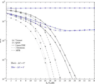
Figure 5: Linear array: BER performance for size-64 constellations with a frequency selective channel and an angle error regarding to transmission direction θ.
assure a better separation of the data streams transmitted for the different users. For that reason, in the following results we only consider constellations’ sizes of 64.
Figure 5 shows the BER (Bit error rate) performance results for both constellations types with 64 symbols for a severely time-dispersive channel and a linear arrangement. As we can see from this figure, when the angle error is null for 3 iterations the performance is close to the matched filter bound (MFB). This means that the degradation on system’s performance is mainly due to errors on the angle estimation in which the constellation is optimized. It becomes clear that due directivity other users are unable to decode efficiently the transmitted data to the user i when they do not know the direction θi, despite the power level of the sent signal. We can compare this scenario to a CDMA (Code Division Multiple access) case, where all the users transmit orthogonal data streams with the same power, but now the separation is assured by constellation directivity instead orthogonal spreading sequences. From the results, it becomes obvious that the best choice are Voronoi constellations since the system directivity is higher due to higher number of RF branches needed to decompose these constellations. Obviously, this leads to a more sensitive system to the direction θ associated to each user and achieves a lower interference among users.
5. CONCLUSIONS
In this paper we considered a transmission system comparable with MIMO that allow independent transmissions among several users by using directivity at information level. The results showed that due to the directivity in the transmitted constellations any angle error against the desired direction
θ in which the information is optimized has a major impact in system performance and the ability
to decode the information. This means that other users are unable to decode with success data streams belonging to other users. Moreover, the separation between users can increase with higher spectral efficiencies. Besides the aspects already mentioned, this approach assures also better power efficiency given that the decomposition of multilevel constellations into constant envelope signals.
ACKNOWLEDGMENT
This work was supported in part by CTS multi-annual funding project PEst-OE/EEI/UI0066/2011, IT multi-annual funding project PEst-OE/EEI/LA0008/2013, GALNC EXPL/EEI-TEL/1582/20-13, EnAcoMIMOCo EXPL/EEI-TEL/2408/2013 and CoPWIN PTDC/EEI-TEL/1417/2012 GAL-NC (EXPL/EEI-TEL/1582/2013).
REFERENCES
1. Andrews, J. G., “Interference cancelation for cellular systems: A conterporary overview,” IEEE
Wireless Comm., Vol. 12, No. 2, 19–29, Ap. 2005.
2. Yan, X., X. Wang, G. Leus, G. Yue, and J. Jiang, “Interference management in wireless communication systems: Theory and applications,” EURASIP Journal on Wireless
Commu-nications and Networking, Vol. 2010, Hindawi Publishing Corp., New York, NY, United States,
Jan. 2010.
3. Goldsmith, A., S. A. Jafar, N. Jindal, and S. Vishwanath, “Capacity limits of MIMO channels,”
IEEE J. Select. Areas Commun., Vol. 21, No. 5, 684–702, 2003.
4. Gesbert, D., M. Kountouris, R. W. Heath, Jr., C. B. Chae, and T. Slzer, “Shifting the MIMO paradigm: From single user to multiuser communications,” IEEE Signal Processing Magazine, Vol. 24, No. 5, 36–46, Oct. 2007.
5. Marques da Silva, M. and F. A. Monteiro, MIMO Processing for 4G and Beyond: Fundamentals
and Evolution, CRC Press Auerbach Publications, FL, USA, May 2014, ISBN: 9781466598072,
http://www.crcpress.com/product/isbn/9781466598072.
6. Montezuma, P. and A. Gusm˜ao, “Design of TC-OQAM schemes using a generalised nonlinear OQPSK-type format,” IEE Elect. Letters, Vol. 35, No. 11, 860–861, May 1999.
7. Astucia, V., P. Montezuma, R. Dinis, and M. Beko, “On the use of multiple grossly nonlin-ear amplifiers for higly efficient linnonlin-ear amplification of multilevel constellations,” Proc. IEEE
VTC2013-Fall, Las Vegas, NV, US, Sep. 2013.
8. Tse, D. N. C. and P. Viswanath, Fundamentals of Wireless Communications, Cambridge Uni-versity Press, Cambridge, UK, 2005.
9. Benvenuto, N. and S. Tomasin, “Block iterative DFE for single carrier modulation,” IEE Elect.
Letters, Vol. 39, No. 19, 1144–1145, Sep. 2002.
10. Dinis, R., R. Kalbasi, D. Falconer, and A. Banihashemi, “Iterative layered space-time receivers for single-carrier transmission over severe time-dispersive channels,” IEEE Comm. Letters, Vol. 8, No. 9, 579–581, Sep. 2004.
11. Benvenuto, N. and S. Tomasin, “Iterative design and detection of a DFE in the frequency domain,” IEEE Trans. on Comm., Vol. 53, No. 11, 1867–1875, Nov. 2005.
12. Luzio, M., R. Dinis, and P. Montezuma, “On the design of linear receivers for SC-FDE schemes employing OQPSK modulation,” Proc. IEEE VTC2010-Fall, Ottawa, Sep. 2010.
13. Luzio, M., R. Dinis, and P. Montezuma, “On the design of iterative FDE receivers for OQAM modulations,” IEEE GLOBECOM’10 — BSCFDC Workshop, Miami, Apr. 2010.
14. Gusm˜ao, A., P. Torres, R. Dinis, and N. Esteves, “A turbo FDE technique for reduced-CP SC-based block transmission systems,” IEEE Trans. on Comm., Vol. 55, No. 1, 16–20, Jan. 2007. 15. Dinis, R., P. Montezuma, N. Souto, and J. Silva, “Iterative frequency-domain equalization for