2011
Aarón Vicente
Hernández Medina
Tintas para o fabrico de enxertos de CaP porosos
por robocasting
2011
Aarón Vicente
Hernández Medina
Tintas para o fabrico de enxertos de CaP porosos
por robocasting
Dissertação apresentada à Universidade de Aveiro para cumprimento dos requisitos necessários à obtenção do grau de Mestre em Maestrado Europeo em Ciencia de Materiais, realizada sob a orientação científica do DrJose Ma. Ferreira, Professor Associado com Agregacao do Departamento de Engenharia Ceramica e do Vidro da Universidade de Aveiro
o júri
Presidente Prof. Dra. Maria Margarida Tavares Lopes de Almeida
professora auxiliar do Departamento de Engenharia Ceramica e do Vidro da Universidade de Aveiro
Vogal-Arguente Principal Prof. Dr. Fernando Jorge Lino Alves
professor associado da Faculdade de Engenharia da Universidade do Porto
Vogal- Orientador Prof. Dr. José Maria da Fonte Ferreira
professor associado do Departamento de Engenharia Ceramica e do Vidro da Universidade de Aveiro
Co- Orientador Dra. Alexandra Lemos
Agradecimentos Agradeço primeiramente a mina família, não só a os meus pais e irmão, também a tanta pessoas que me ajudaram a ser melhor e a não deixar de lutar por os meus sonhos.
Ao Professor José Maria Ferreira, meu orientador, pela oportunidade de trabalhar no fascinante mundo dos biomateriais, pelo seu apoio, encorajamento, paciência e pela amizade ao longo deste tempo que tive o prazer de trabalhar com ele. Obrigado por confiar em mim.
Á Doutora Alexandra Lemos pela sua co-orientação, pelo apoio, pela oportunidade de discutir ideias, sejam elas quais forem, pelas sugestões imprescindíveis, pelas longas conversas de reflexão sobre questões fundamentais, pela agradável convivência e pelo exemplo de grandeza como pessoa pesquisadora.
As pessoas do Departamento de Materiais da Universidade de Badajoz, pelo apoio e hospitalidade brindada durante a minha colaboração com eles.
Aos técnicos do Departamento de Engenharia e do Vidro por tão atenciosamente me terem auxiliado sempre que necessitei da sua colaboração.
palavras-chave Hidroxiapatite, fosfatos de cálcio, implantes, robocasting, processamento coloidal, tintas, suspensões
resumo Actualmente, o desenvolvimento de novos biomateriais e de técnicas alternativas para o fabrico de implantes ortopédicos é muito importante. O objectivo da engenharia de tecidos é desenvolver soluções efectivas para o tratamento e regeneração óssea a longo prazo. O presente trabalho mostra uma nova alternativa para a fabricação de implantes ósseos com porosidade controlada, a qual pode ser modelada para a optimização dos mesmos. Foram preparadas tintas coloidais com elevada concentração de sólidos com o objetivo de poderem ser injectadas através da técnica de robocasting. Fosfatos de cálcio foram sintetizados e dopados com diferentes concentrações de estrôncio. Suspensões concentradas com 60 vol% de sólidos foram preparadas e modificadas de forma a alcançar as propriedades reológicas necessárias à conformação por robocasting. Diferentes arquiteturas tri-dimensionais foram preparadas por deposição robótica, e depois secas e sinterizadas, mantendo a sua forma inicial.
keywords Hydroxyapatite, calcium phosphate, scaffolds, implants, robocasting, colloidal processing, inks, suspensions
abstract Nowadays, the development of new biomaterials and alternative techniques for the fabrication of orthopedic implants are of great importance. The objective of tissue engineering is to provide effective solutions in the treatment and healing of bone defects in a long-term. The present work gives a new option for the fabrication of bone scaffolds with controlled porosity that can be designed for the optimization of the implants. Highly concentrated colloidal inks were prepared with the aim of using them in a robotic deposition device called robocasting. Three types of calcium phosphate powders doped with strontium were synthesized, calcined, comminuted and characterized. Concentrated suspensions with 60 vol% of solid content were successfully prepared and their physical properties modified afterwards in order to obtain inks with optimal behavior for direct-write assembly. Different three-dimensional architectures were made through robotic deposition, then dried and sinterized maintaining their shape.
Figure 1. Anatomy of the Bone
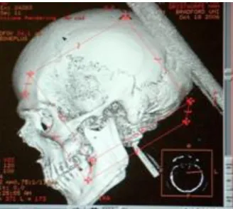
Figure 2. Three-dimensional view of a skull from a CT scan
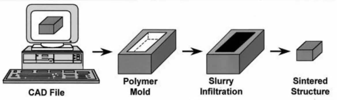
Figure 3. Indirect processing of ceramic structures via rapid prototyping processes. Figure 4. Calcium meta-phosphate human temporal bone that was formed by SLS
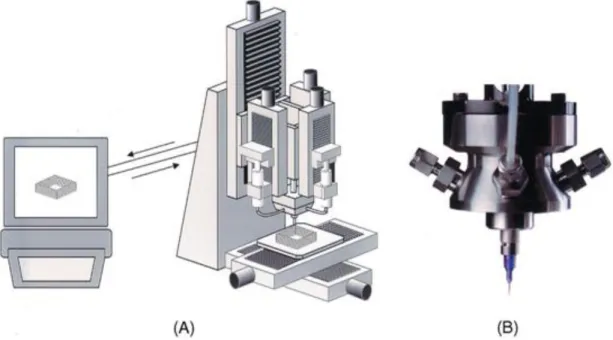
Figura 5. (A) Schematic illustration of robocasting equipment and (B) optical view of robocasting head Figure 6. SEM micrographs showing the HA scaffold morphology after sintering at 1300oC for 2 h
Figure 7. Schematic illustration of the interaction potential energy and relevant length scales
Figure 8. Schematic illustration of adsorbed anionic polyelectrolyte species on an ideal ceramic surface as a function of pH and ionic strength
Figure 9. Schematic illustration of the robocasting fabrication process.
Figure 10. Particle size distribution of CaP powder with 10%Sr calcined at 1000oC for 2hr and ball
milled during 15+15+15min.
Figure 11. X-rays spectrum from 10%Sr powders calcined at 1000oC.
Figure 12. Types of rheological behavior exhibited by colloidal dispersions:
Figure 13. 60vol% 0%Sr CaP suspensions with different concentrations of Targon (T)
Figure 14.CaP suspensions 55vol% 0%Sr 1wt%T with increasing amounts of HMC.
Figure 15.Comparison of the viscosifying effect of HMC, PVP and HMC+PVP (logaritmic scale) Figure 16.Effect of the strontium content on the suspension behavior (logarithmic scale) Figure 17. Maximum values of PEI added to the CaP inks (logarithmic scale)
Figure 18. Schematic representation of oscillatory behavior as a function of frequency for (A) liquid, (B) gel, and (C) solid respons
Figure 19.Oscillatory frequency sweep results from inks with no addition of PEI Figure 20. Oscillatory frequency sweep results from inks with 0 .4wt% PEI Figure 21.CaP scaffolds fabricated by robocasting
List of Tables
Table1. Class of Materials Used in the Body
Table 2. Density and mechanical properties of dense ceramics
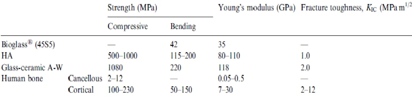
Table 3. Mechanical properties of bioactive ceramics and human cortical and cancellous bones Table 4. Volume Statistics (Arithmetic) of particle sizes from 10%Sr CaP powder.
List of Symbols and Abbreviations
Polymethylmethacrylate - PMMA Extra cellular matrix – ECM
Beta tricalcium phosphate - β-TCP Hydroxyapatite – HA
Biphasic calcium phosphate – BCP Rapid prototyping – RP
Solid free-form – SFF
Computer aided design – CAD Computarized tomography – CT Magnetic resonance imaging – MRI Three-dimensional printing – 3DP Laminated object manufacturing – LOM Fused deposition modeling – FDM Selective laser sintering – SLS Electron beam melting – EBM Shear or elastic modulus – G’ Loss or viscous modulus – G” Monocalcium phosphate – MCP Temperature – T Boltzmann constant - kb Volume fraction –φ Polyvynilpyrrolidone - PVP Hydroxy-propyl-methylcellulose – HMC Polyethylenimine - PEI
Objectives
The main objective of the present work was to prepare a highly concentrated colloidal suspension with the optimal physical and rheological properties to be used as a suitable bioceramic ink for the fabrication of scaffolds with meso-scale spanning features through the direct-write assembly technique. The specific objectives are the following:
Preparation of calcium phosphate (CaP) powders and their characterization through particle size distribution (PSD) and X-ray diffraction (DRX)
Preparation of highly concentrated suspensions by mixing the powders with a solution of water and dispersant
Preparation of the ink by tailoring the rheological properties of the suspensions with the use of viscosiying and flocculating agents
Fabrication of the scaffolds using the CaP inks with the desired properties
Sintering of the obtained specimens after they are properly dry with the purpose of enhancing their mechanical resistance and get rid of the polymeric agents
2. Literature Review ... 3
2.1. Biomaterials ... 3
2.2 Tissue Engineering ... 4
2.3. Calcium Phosphates ... 7
2.4. Solid Free-form (SFF) Fabrication Techniques ... 10
2.4.1. Robocasting ... 13
2.5. Colloidal Processing ... 16
2.5.1. Interparticle Forces ... 16
2.5.2. Suspension Rheology ... 20
3. Experimental Procedures ... 21
3.1. Powder Preparation and Characterization ... 21
3.2 Ink Preparation and Characterization... 22
3.3. Fabrication of the scaffolds ... 25
4. Results and Discussion ... 26
4.1 Particle size distribution ... 26
4.2. X-Ray diffraction characterization ... 27
4.3 Rheological Measurements ... 28 4.3.1. Viscometry mode ... 28 4.3.2 Oscillatory mode ... 32 4.4 Robocasting of scaffolds ... 34 Conclusions ... 38 References ... 39
European Master in Materials Science 2
1. Introduction
Every year, there are millions of people around the world who need some kind of prostheses, and the need for all kinds of implants became very well known in our societies. The medicine field has experience great advances in the last decades and the main motivation for this was to increase life expectancy. According to the demographic forecasts for the near future in the developed countries, the percentage of elder people would be considerably bigger than in infants and teenagers.
The massive longevity of the population encourages the researchers to develop new solutions that help to maintain a good quality of life at the elder age. The new motto is not only to preserve the life of patients but also to provide reliable long-term medical solutions. This has also positively influenced the surgical procedures bringing improvements in the techniques, and accelerated the development of new prostheses and orthopedic implants to replace or regenerate bone tissues. These should be made of biocompatible materials that ensure an acceptable lifetime for the patient, and provide the best performance.
When bone suffers damage due to a fracture, disease (osteoporosis, for instance) or wear (in the case of joints), and there is a need to replace it either entirely or in a partial manner, the traditional method has been to use either autograft (a graft of the patient´s own bone) or allograft (a graft from another human, via a bone bank). The former requires a additional operation to harvest the bone (from the iliac crest, for example), and this results in increased pain, risk of infection, post-operative care and cost. The quantity of autograft available is limited according to each patient. Allograft bone is also limited in availability, and carries a serious risk of disease transmission, as well as non-optimal performance of the graft.1
The new approach is to produce implants made of biomaterials to replace bone, which should match the functional requirements and characteristics of the natural
European Master in Materials Science 3
tissue. This means that orthopaedic implants should be biocompatible, corrosion resistant, mechanically resistant, and promote osseointegration.
2. Literature Review
2.1. Biomaterials
A biomaterial can be defined as any material used to restore a part or function of natural living tissue or organ in the body in a safe, reliable and physiologically compatible way.2 Biomaterials can be either synthetic as polymers, metals, ceramics and composites, or even biological as wood, bone and cells. Some examples of biomaterials as well as its advantages, disadvantages and possible applications are shown on Table 1. They can be also classified according to their biological behaviour based on the response of the recipient living tissue or environment:3
Bioinert materials, when introduced to the body do not cause any reaction or interact with the biological tissue, meaning that the host won´t recognized them as a strange body. Examples: titanium, zirconia and alumina.
Biotolerant materials are not necessarily rejected by the host but rather moderately accepted by the recipient tissue which encapsulates the implant with a fibrous interface. Examples: stainless steel, glass, chromium-cobalt fibers and polymethylmethacrylate (PMMA).
Bioactive materials may cause a reaction or have an effect on the living environment, also due to their composition are capable of forming a direct link with the tissue. In the case of bone grafts, these materials have calcium and/or phosphate ions that help them to get attached to the surrounding bone. Examples: hydroxiapatite, bioactive glasses.
Biodegradable/reabsorbable materials are those that suffer of slow degradation and gradual substitution of the host tissue. Examples: tricalcium phosphate and bioactive glass.
European Master in Materials Science 4
In order to achieve an optimal restoration of a bone graft, three different processes must take place:4 1) osteoinduction- estimulation for the production of sufficient osteoblasts (the mononucleate cells responsible for bone formation) and the factors to promote their differentiation are provided, 2) osteoconduction- these cells should be able to adhere, grow and infiltrate on the implant, and finally 3) osseointegration- the successful anchorage of an implant achieved by direct bone to implant contact. Looking for the ideal biomaterial for a specific bone restoration might become difficult considering that some materials match and even exceed the required mechanical properties, but do not promote these processes, or it can happen to be the other way around. For these reason, the best option is to combine two biomaterials with different mechanical, structural and chemical properties that can complement each other in a balanced manner.
Table1. Class of Materials Used in the Body2
2.2 Tissue Engineering
When tissue is severely damaged or lost, including its extracellular matrix (ECM) it is not possible to restore it just with the supply of drugs, structural proteins and growing factors. It is necessary to provide a new biological or artificial ECM so the cells can
European Master in Materials Science 5
produce neotissue. This substitute of the native matrix is called “scaffold” and it is basically a three-dimensional support that serves as a template for the infiltration and proliferation of cells into the damaged tissue or organ.5 The scaffold must have the architecture on which neotissue is desired to grow and provide sufficient support while the tissue is growing. In the case of bone scaffolds for orthopaedic applications, these should have enough mechanical resistance to withstand the required degree of loading during their use in vivo.
Bone is constituted by different types of cells (osteoprogenitor cells, osteoblasts, osteocytes, osteoclasts) which are in need of proper vascularization, and they are protected by a strong composite matrix made of interwoven fibrous proteins (collagen, adhesion proteins). Bone matrix is a natural composite significantly mineralized (65% by weight) with a complex structure organized into lamellae (plate-like structure).6 It consists of collagen bundles which have been infiltrated by a crystalline mineral phase very similar to synthetic hydroxyapatite (HA)Ca10(PO4)6(OH)2. The main
difference is that some of the tetrahedral [PO4]3- phosphate groups have been
replaced by planar [CO3]2- carbonate groups, so it can be described as carbonated
hydroxyapatite (CHA). It has been shown that “collagen and the apatite mineral form continuous, independent, interpenetrating networks”.6-8
As it can be seen of Fig. 1, bone is anatomically differentiated depending on its structural features and it can be defined as either compact (cortical) bone or spongy (cancellous or trabecular) bone. The compact bone is very dense with only 10% of internal porosity, and the spongy bone on the other hand has an interconnecting porous architecture ranging from 50 to 90% of porosity and made up of curvilinear struts called trabeculae.6 While the cortical bone is mainly found on the shafts of long bones like the femur and tibia, the cancellous bone appears at the ends of long bones and in the vertebral body.
Bone scaffolds should have a certain degree of porosity according to the targeted spot of the bone to be restored. This porosity should be comprised of macro- and
European Master in Materials Science 6
micro-interconnected pores that not only help to mimic the architecture of the replaced piece, but also contributes to the mass transport properties necessary for the osteoinduction, osteoconduction and osseointegration. Nevertheless, porous scaffolds are inherently weak, especially if they are made of calcium phosphates, and it is necessary to optimize their mechanical resistance so that they can give the required support while bone regenerates and they are slowly reabsorbed. This can be done by characterizing and simulating the mechanical performance of each specific three-dimensional architecture with the aid of a finite element modelling (FEM) software.7 Indeed, many features must be taken into account when developing an optimal scaffold for a certain application; properties of the material, morphology and structure, type and volume fraction of the pores, as well as its interfacial state and degradation rate.8
European Master in Materials Science 7
2.3. Calcium Phosphates
Calcium phosphate biomaterials are polycrystalline ceramics deriving from individual crystals of a highly oxidized substance (calcium salt) that have been fused together. The two most widely used are tricalcium phosphate Ca3(PO4)2 (in its β-TCP phase or
β-whitlockite), and hydroxyapatite Ca10(PO4)6(OH)2.10 Both materials are known to be
biocompatible, osteoconductive and to promote osseointegration. However, they are not osteoinductive, meaning that they are uncapable of producing bone in the absence of bone cells. The main differences between these two materials is that tricalcium phosphate (TCP) presents faster in vivo degradation (due to its higher solubility in water), while hydroxyapatite provides better mechanical resistance.8-10 These bioceramics have been used for decades in orthopaedic and maxillofacial applications including: repair of bone and periodontal defects, alveolar ridge augmentation, ear implants, maxillofacial reconstruction, spine fusion, bone space fillers, bone cement additives, composites and metal implant coatings.8 Both of these two biomaterials show a promising future for bone tissue engineering applications by the fabrication of scaffolds.
Tricalcium phosphate and hydroxyapatite can even be mixed into a biphasic calcium phosphate material (BCP) that combines the great biodegradability of β-TCP with the strong mechanical properties of HA.11 Increasing the β-TCP/HA ratio will give a more biodegradable material since β-TCP dissolves preferentially from its matrix, releasing calcium and phosphate ions to the media, enhancing the in vivo activity and decreasing the resorption time. Simultaneously, a higher β-TCP/HA ratio will diminish the mechanical strength in the BCP material. However, it has been proved that the mixture of calcium phosphates turns out to be the ideal choice.11
Sintered hydroxyapatite has higher crystallinity than mineral bone and as a consequence a lower rate of degradation, so it can take more than five years to be reabsorbed by the body, while tricalcium phosphate can be completely degraded in one or two years.12
European Master in Materials Science 8
The α-phase of tricalcium phosphate is unstable at low temperatures and it is obtained by heating the β-phase at temperatures higher than 1150oC, although the precise temperature at which this occurs has not been found yet. On the other hand, β-TCP cannot be obtained by direct precipitation, it is rather the result from the calcinations of Ca deficient apatites at 700-800oC, together with water loss as described by the following equation:13
Ca9(HPO4)(PO4)5(OH) → 3Ca3(PO4)2+H2O (1)
In the case of HA, it can be obtained by different methods such as 1) precipitation, 2) thermal treatments at high temperature or even 3) hydrothermal conversion from coral.8-14Since hydroxyapatite is non-stoichiometric it can be made by mixing solutions with calcium and phosphate ions in a Ca/P=1.67 ratio with a pH>9. In the second method, HA is obtained by solid state reactions starting from other calcium phosphates (monetite or brushite) that contain CaO, Ca(OH)2 or CaCO3 at
temperatures around 1200oC and having an atmosphere with the same volumes of water vapour (as a source of OH- groups) and oxygen.14On the third method, HA replaces the aragonite while preserving the porous structure. The following exchange takes place:18
10CaCO3 + 6(NH4)2HPO4+2H2O → Ca10(PO4)6(OH)2+6(NH4)2CO3+4H3CO3 (2)
In order to compare the properties of different calcium phosphate bioceramics (HA, β-TCP and BCP) J.Franco et al. prepared and tested dense ceramic samples by cold isostatic pressing at 1.4GPa followed by sintering in air.11 The results are shown on Table 2. The densities were determined by the Archimedes method. Flexural strengths were measured in four-point bending, while plane strain fracture toughness measurements were performed on single end notch bend specimens loaded in three point bending.
On Table 3, the mechanical properties of hydroxyapatite are compared with those from other bioceramics and also from human bone (cancellous and cortical). As it can
European Master in Materials Science 9
be noted, HA presents compressive strength values that are five times higher than compact bone and twice bending strength. However, cortical bone shows much better fracture toughness and significantly lower elastic modulus. For this reason HA is not a good option for repairing defects in high-load bones, such as femoral and tibial bones.
Table 2. Density and mechanical properties of dense ceramics11
Table 3. Mechanical properties of bioactive ceramics and human cortical and cancellous bones15
Lately, ionic incorporations into calcium phosphates bioceramics, such as magnesium (Mg), zinc (Zn) and strontium (Sr), have had increasing interest in the bone tissue engineering field due to properties enhancement and the benefitial mechanisms that they induce after implantation.16 In the case of Sr, it became really popular in the prevention and treatment of osteoporosis as a ranelate compound due to its ability to prevent bone loss by a mechanism of reducing bone resorption and promoting bone formation.17 In vitro studies have shown that strontium ranelate increases collagen and non-collagen protein synthesis, enhances preosteoblastic cell proliferation, depresses osteoclast differentiation, and reduces the osteoclasts function.18Once it is administrated in the body as Sr salt, it seeks for bone and diffuses into the Haversian capillaries walls until it reaches the extracellular fluid where it can be deposited into
European Master in Materials Science 10
the mineral structure or substitute the Ca positions in bone crystals thanks to their chemical analogy. 17
2.4. Solid Free-form (SFF) Fabrication Techniques
Lately, the different additive manufacturing (AP) techniques provide a suitable solution for designing and producing patient oriented customized implants at a reasonable cost. Such techniques are or also called solid free-form fabrication (SFF) or layered manufacturing since it builds an object layer by layer via the processing of solid sheet, liquid or powder material, using two- dimensional sections.19 This technology allows producing dimensionally-accurate three dimensional (3D) models directly from computer-aided design (CAD) files without using hard tooling, moulds or dies.19
Fortunately, the modern medical imaging techniques like computerized tomography (CT) scanning or magnetic resonance imaging (MRI) are also based on layers and the format of the images can be transformed to a CAD file (Fig.2). This allows to take the medical images of the injured bone from any patient, and to use them to design and produce orthopaedic implants through additive manufacturing.
European Master in Materials Science 11
The rapid manufacturing systems available on today include stereolitography, fused deposition modelling (FDM), selective laser sintering (SLS), ink-jet and three dimensional printing (3DP), hot-melt printing, electron beam melting (EBM), and robocasting.19
Conventional porous scaffold fabrication methods (including solvent casting along with particulate leaching, gas foaming, freeze drying, fibre meshing, melt moulding, phase separation and supercritical-fluid technology) do not provide precise control over pore size, geometry and spatial distribution.21 As a solution, SFF techniques are very useful for the design and fabrication of bone scaffolds with complex shapes, giving the advantage to create optimal internal porous structures that can provide the desired mechanical resistance along with the required permeability and diffusion properties, being possible to create interconnected porosity for osteoconduction and even internal channels for the micro-vascularization of the scaffold.21
In order to fabricate bioceramic scaffolds, some of these solid freeform techniques fabricate the scaffold via an indirect process that involves the preparation of a lost mould (negative replica of the desired structure) made of an organic material (usually polymer or wax). The ceramic slurry is infiltrated into the mould, then dried and heated up at the melting temperature of the secondary material (to get rid of it), and finally the scaffold is sintered at a higher temperature.22 Such is the case of stereolitograhy and fused deposition modelling.
European Master in Materials Science 12
The main problem with this indirect procedure is that the removal of the polymer or wax can delay for too long, it often takes days to obtain scaffolds that are free of organic defects.23
The 3DP technique consists on distributing a powder over a surface over which a multi-channel ink-jet head selectively applies an adhesive (binder) which hardens the desire geometry of each section. The platforms move vertically until the piece is entirely finished by simultaneously covering the surface each time with a new layer of powder. There have been attempts to used CaP powders to produce scaffolds, though the main constraint is the toxicity of the binders.24 Also, the process itself produces scaffolds with rough surfaces and limited feature resolution.23
Similarly, SLS also uses powder to make the template, but instead of injecting the binder it uses a sintering device that consists of an automated infrared beam which covers the section that will become solid. Researchers from the University of Texas at Austin,25 developed an indirect process for preparing porous, shaped implants made of calcium meta-phospthate powder (with a calcium to phosphorus molar ratio of 0.9) by selective laser sintering. Such powder is obtained after thermally reacting a mixture of monocalcium phosphate (MCP, Ca(H2PO4)2) and dicalcium phosphate
(DCP, CaHPO4) at 1000 C for 12 h, then allowing to cool at 500 oC and the
quenching in water. Afterwards, the powder was comminuted in a mechanical grinder at 20,000 rpm during 2 min, and then sieved with a size fraction of 106-125 µm in order to give a pore size distribution of 10-200 µm for the implant.
The indirect process for making CaP scaffolds through SLS uses a fusible polymer binder that is either coated on the desired substrate particles, typically by fluidized bed processes, or simply mixed with those particles.The obtained implants (Figure 4) had a very low relative density (50%) due to the porosity, and their compressive strength (70 MPa) was not enough for load-bearing applications. However, they are suitable for maxillofacial applications of bone replacement, since in the in-vivo tests exhibited good biocompatibility and osseointegration. 25
European Master in Materials Science 13 Figure 4. Calcium meta-phosphate human temporal bone that was formed by SLS from
CT slice data (left); SEM of the fracture surface of a calcium phosphate bone made by SLS and post-processed (right) 25
2.4.1. Robocasting
Also called direct-write assembly, differs from the other SFF techniques being the only one to allow building ceramic scaffolds using water-based inks with minimal organic content (<1wt%) without the need for sacrificial support materials or mould.26This technique consists on the robotic deposition of highly concentrated colloidal suspensions (inks) capable of fully supporting their own weight during assembly. A 3D structure is printed directly as a network of ink rods through the deposition nozzle.26Robocasting allows to produce periodic structures with spanning features that vary between ~100µm and a few millimetres, with rod diameters that ranges also in the meso-scale.
When preparing the ink, the important relations between colloidal stability, rheological behaviour, and ceramics fabrication must be taking into account. First, they must exhibit a well-controlled viscoelastic response; that is, they must be able to flow through a deposition nozzle and then “set” immediately to facilitate shape retention of the deposited features even as they span gap in the underlying layers.27 Second, they must contain high colloid volume fractions to minimize drying-induced shrinkage after assembly; that is, the particle network must be able to resist compressive stresses arising from capillary tension.27 To obtain an ink with such characteristics, careful control of the colloidal forces is necessary to prepare a highly concentrated stable
European Master in Materials Science 14
suspension and then induce a system change (by modifying the pH, ionic strength or solvent quality) that causes a fluid-to-gel transition, see Fig.5.
Figura 5. (A) Schematic illustration of robocasting equipment and (B) optical view of robocasting head,
which deposits a concentrated colloidal suspension in a layer-by-layer build sequence to generate complex, three-dimensional parts.28
The physical parameters that take place at the deposition of the ink through the nozzle are described by the following equation: 29
𝛕r=r ∆P/2ℓ
(3)
where
∆P
is the pressure gradient applied along the nozzle length that provokes a radially varying shear stress (𝛕r
),r
is the radial position within the nozzle (e.g. r=0 at the centre axis and r=R at the nozzle wall). Plug or laminar flow may occur within the nozzle depending upon the velocity profile and the ink stability.29In recent years, different studies have been done remaining the fabrication of calcium phosphate scaffolds (HA, β-TCP and BCP) by direct-write assembly.7,11,21,23
The results have been successful since it has been possible to produce scaffolds with relatively complex architectures that were dried, sintered and characterized afterwards. This encourages researchers to continue working on this line.
European Master in Materials Science 15
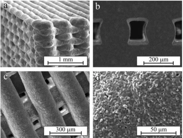
For instance, P. Miranda et al. have studied the mechanical optimization of porous ceramic scaffolds through the understanding and optimization of their macro- and micro-structure.7,26,30 This can be done with the aid of robocasting and the finite element method (FEM). They have fabricated HA andβ-TCP scaffolds consisting of a 3D square mesh of interpenetrating rods and tested them under uniaxial compression at different directions. In Fig.6 are shown some scanning electron microscope (SEM) images from one of the HA scaffolds. The ink used for robocasting had a final solid content of 35 vol%. Each layer from the CAD file consisted of parallel rods spaced 400 µm from centre to centre. The rods from adjacent layers are orthogonal and the spacing between layers was set to 225 µm. The external dimensions of the scaffolds were set about 10x10x10 mm so that a total of 44 layers were deposited.30
Figure 6. SEM micrographs showing the HA scaffold morphology after sintering at 1300oC for 2 h: (a) general view, (b) cross-sectional view showing the microstructure within the rods, (c) printing plane
European Master in Materials Science 16
2.5. Colloidal Processing
The term “colloid” is used to define any particle that possesses at least one dimension in the size range 10−3−1 µm while dispersed in a liquid or gas phase. Colloidal systems have a large contact area between particles and the dispersing medium.28 For this reason, surface forces have a strong effect on the behaviour of the suspension. Colloidal processing involves five different steps: 1) powder synthesis, 2) suspension preparation, 3) consolidation into the desired component shape (robocasting), 4) removal of the solvent phase (water and additives), and 5) densification (sintering) to produce the final microstructure required for optimal performance. This last step may also help to get rid of unintentional heterogeneities (or defects) introduced at any stage of the fabrication process. 28
2.5.1. Interparticle Forces
Depending on the magnitude and nature of the interparticle forces, colloidal suspensions can present a 1) dispersed, 2) weakly flocculated, or 3) strongly flocculated state. In the first state, the individual colloids are repelled when they nearly approach each other, having a repulsive barrier >>kbT. In the second state,
colloids are aggregated into a shallow secondary minimum with a well depth≈2−20 kbT, having either the formation of isolated clusters (also called flocks) in suspension
at lower volume fractions than the gel point (ᵠ<ᵠgel) or a particle network at higher
volume fractions (ᵠ≥ᵠgel).28When this happens, there is an equilibrium separation
distance between aggregated particles. On the other hand, in the coagulated or strongly flocculated state, particles aggregated into a deep primary minimum, forming either discrete clusters or a touching particle network, depending on the concentration of the suspension.
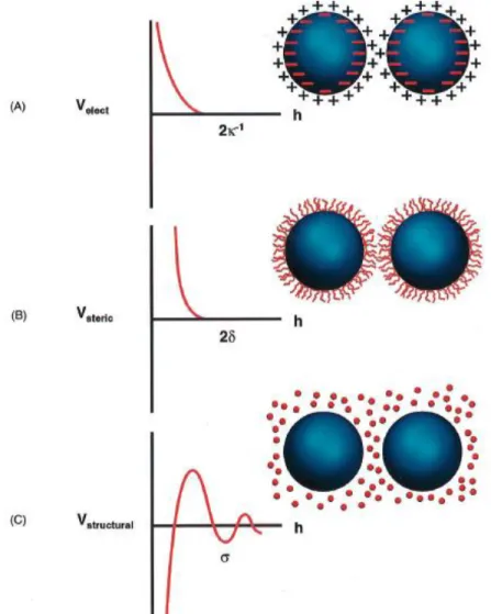
The stability of the suspension is controlled by the total interparticle potential energy, Vtotal, which can be described as follows: 28
European Master in Materials Science 17
Where VvdW is the attractive potential energy due to long-range van der Waals
interaction between particles, Velec the repulsive potential energy resulting from
electrostatic interactions between like/charged particle surfaces, Vsteric the repulsive
potential energy resulting from steric interactions between particles surfaces coated with adsorbed polymer species, and Vstructural the potential energy resulting from the
presence of nonadsorbed species in solution that may either increase or decrease suspension stability (Fig.7).
Figure 7. Schematic illustration of the interaction potential energy and relevant length scales for
(A) electrostatic, (B) steric, and (C) structural contributions, where k−1 is the effective double-layer thickness, ᵟ the adlayer thickness, and σ the characteristic size of species resulting in ordering within
European Master in Materials Science 18
There are five ways to modify the Vtotal and consequently the stability of a colloidal
suspension by tailoring the different types of interparticle forces: 28
a) van der Waals forces:Long-range forces from vdW interactions are omnipresent and always attractive between similar particles. These can be mitigated within the suspension until reaching the desired degree of stability. One approach is to completely diminish by suspending particles in and index-matched solvent.
b) Electrostatic forces: In aqueous suspensions, the stability can be modified by providing similar charges of sufficient magnitude on the colloids surfaces. As predicted by the DLVO theory, colloidal systems can become unstable when the ionic strength is increased or the pH is adjusted toward the isoelectric point (IEP). However, it may be difficult to succeed generating stable dispersion based only on this approach. There may be solubility concerns that limit the working pH range, also an extended double-layer thickness can cause unacceptable drying shrinkage.
c) Steric forces: Organic particles that can be adsorbed by the colloids are often supplied to the system to induce steric repulsion.This can be done in aqueous and non-aqueous dispersions. The added particles may have different molecular architectures such as homopolymers, diblock copolymers, comblike copolymers, and functionalized short chain dispersants.The density and thickness (ᵟ) of the adsorbed layers should be enough to vanquish the vdW forces between particles and to prevent connecting flocculation. In order to have steric interactions, the particles must approach each other at a separation distance less than twice the adlayer thickness. d)Electrosteric forces: polyelectrolyte species are widely used in colloidal suspensions to achieved both steric and electrostatic stabilization. These additives have at least one type of ionisable segment (e.g. carboxylic or sulfonic acid groups) and molecular architectures that include homopolymers, like poly(acrylic) acid, or block copolymers with one or multiple ionisable groups. Adsorption of these species is strongly influencedby the physical and chemical features of the colloids surfaces and the solvent medium. For instance, if the surfaces of the targeted particles are
European Master in Materials Science 19
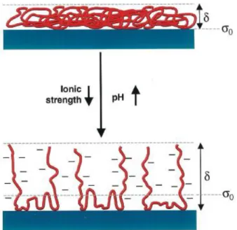
oppositely charged with respect to the polyelectrolyte, then adsorption is strongly encouraged. At small adsorbed amounts, these additives can induce flocculation due to surface change neutralizations or bridging mechanisms. At higher adsorbed amounts, colloid stability increases thanks to the long-range repulsive forces generated from electrosteric interactions. In Fig. 8, it is represented an example of modifying the adsorption behaviour and conformation of polyelectrolyte additives by tailoring the solvent conditions (e.g. pH and ionic strength). Assignments of the vdW plane, the plane of charge (σ0) and the steric interaction length (ᵟ) must be taken into
account when modelling the colloidal interactions.
Figure 8. Schematic illustration of adsorbed anionic polyelectrolyte species on an ideal ceramic
surface as a function of pH and ionic strength (ᵟ is the adlayer thickness and σ0 the plane of charge). 28
e) Depletion forces: occur between large colloidal particles suspended in a solution of non-adsorbing smaller species (depletants) including polymers, polyelectrolytes, or fine colloidal particles. These can induce either flocculation or stabilization of the bigger particles. Depletion occurs with the presence of a negative depletant concentration gradient near primary particles surfaces. This starts at a distance defined as the depletion layer thickness which is related to the depletant diameter. By
European Master in Materials Science 20
increasing the depletant volume fraction a suspension can experience transitions from stable → depletion flocculation → depletion restabilization.
2.5.2. Suspension Rheology
The critical parameters that govern the rheological behaviour of a colloidal suspension are the following: the apparent viscosity (ƞ), the yield stress under shear (
𝛕y
) and compression (Py), and the viscoelastic properties of the system such as theloss (G”) and the elastic (G´) moduli. All of these can be tailored by the use of the already discussed additives.28
The fabrication of CaP scaffolds by robocasting requires the use of highly concentrated colloidal inks (ᵠ→ᵠmax) that can present excellent shape retention after
the forming the porous structure. It is important to understand the ideal flow behaviour required for the successful ejection of a strong enough filament from the nozzle. If the ink is excessively fluid, it will have no trouble to flow out, however it won´t be able to retain its shape. In the opposite case, if the ink is overly viscous, if will struggle to flow out through the nozzle, and if it does there might occur rupture of the filament several times.
Concentrated inks usually present a viscoelastic behaviour that can be recognized after performing dynamic rheological measurements (or oscillatory techniques). In this type of characterization, a frequency dependant shear stress or strain must be applied to the colloidal system in order to obtain the complex shear modulus (G*), which has a real (elastic, G’) and an imaginary (viscous, G”) component represented as follows: 28
G* = G’+ iG” (5) Where G’= G* cos ᵟ, G”= G* sin ᵟ, and ᵟis the phase angle. When a suspension is purely elastic (solid like), the applied strain and resulting stress are in phase (ᵟ=0), meaning that the energy is completely stored. On the contrary, when a suspension is purely viscous (liquid like), the energy is completely dissipated, and the applied strain
European Master in Materials Science 21
and resultant stress are fully out of phase (ᵟ≈90o
). Thus, a viscoelastic behaviour (gel like) should be at an intermediate range 0<ᵟ<90o
.
3. Experimental Procedures
3.1. Powder Preparation and Characterization
Three types of HA powders with different compositions were prepared as raw materials for the colloidal suspensions. One of the powder compositions was prepared with pure HA while the other two compositions were doped with 5%Sr and 10%Sr. The calculations for the preparation of the solutions used in the synthesis of the powders had the following starting criteria (Ca+Sr) / P= 1.62. Assuming that the initial concentration of the initial P solution was fixed at 1.2M, the concentrations for the solutions of the other precursors were calculated in a way that maintained the starting criteria, meaning that the total concentration of the precursors (Ca and Sr) was 1.94M in the three cases. The quantities for the doping ions used for the synthesis were 0.097M (5%Sr) and 0.194M (10%Sr). The three different powders were prepared by chemical precipitation, starting from calcium nitrate 4-hydrate [Ca(NO3)2∙4H2O] (Panreac Quimica S.A., Barcelona, Spain), di-ammonium hydrogen
phosphate [(NH4)2HPO4] (Vaz Pereira-Portugal, Sintra, Portugal), and strontium
nitrate [Sr(NO3)] (Sigma-Aldrich, Germany), as chemical precursors for calcium,
phosphorous and strontium respectively.
For each powder synthesis, two solutions (P, Ca or Ca+Sr) were prepared with distilled water and predetermined concentrations, and then mixed homogenously using a magnetic agitator at 500 rpm during a few minutes. After stirring, both solutions were filtered through a 53 µm mesh to avoid contaminations and impurities. The Ca solution was poured inside a reactor (previously heated up to 90 oC) which was closed afterwards, and agitation was set at 1000 rpm. Then the P solution was poured inside the reactor using a peristaltic pump (Heidolph Pumpdrive 5206) and the flux rate was set at 86.8 ml/min. Once the complete addition of both solutions in the reactor was finished, ammonium hydroxide (ca. 25%NH3, Sigma-Aldrich) was added
European Master in Materials Science 22
to the mixed solution in order to reach a pH=9 and maintain it. The precursors were let inside the reactor during 2h after addition. At the end of this, the precipitated suspension was removed from the reactor, filtered under vacuum to get the precipitated powder, which was dried at 100oC in an oven to remove the remaining solvent. Then, it was deagglomerated and calcined at 1000oC during 2h with a slope rate of 5 oC/min. Some samples were calcined at lower temperatures (400, 600, 700, 800, and 900oC) for characterization purposes only.
After calcinations, the powders were ball milled in dry state during 15+15+15min. Samples of the three raw powders along with calcined powders at all the mentioned temperatures were subjected to X-ray characterization in order to obtain information of their microstructures and phase changes. After ball milling, the particle size distribution of the powders was analysed in a laser dispersion instrument (COULTER LS230, UK) using a Fraunhofer optical model.
3.2 Ink Preparation and Characterization
The preparation of the CaP ink for robocasting was performed at three different stages: 1) preparation of a concentrated suspension, 2) addition of a viscosifier agent, and finally 3) addition of a gelifying agent. The same powders with the three different compositions (0%Sr, 5%Sr and 10%Sr) were used for this purpose.
The additives employed for the ink preparation were the following: ammonium polycarbonate (Targon 1128, BK Ladenburg, Germany) as a dispersant in order to get highly concentrated CaP suspensions, polyvynilpyrrolidone (PVP K90, mol wt. ~360 000, Sigma-Aldrich) and hydroxy-propyl-methylcellulose (HMC, mol wt. 410 000, Sigma-Aldrich) were used as viscosifying agents, and polyethylenimine (PEI 50% w/v in water, mol wt. 2000, Sigma-Aldrich) was used as gelifying agent.
In a previous work, after comparing the ability of different dispersants for preparing highly concentrated HA suspensions, Targon 1128 revealed to be the most efficient, enabling to achieve up to 50 vol% of solid loading.31 It is an anionic-type dispersant that helps to develop high zeta potentials in the neutral or alkaline pH region where
European Master in Materials Science 23
HA is thermodinamically stable, leading to an increase of the repulsive force among the colloids. Targon’s efficiency as dispersant and electrostatic stabilizer might be related to the composition of the functional groups along its polyelectrolyte chains.31 Also calle hypromellose, HMC is an inert white to off-white powder that can be swelled in water to form a viscous colloidal solution. It can be an enteric film coating material or a matrix binder in solid dosage forms. It is used as a viscosity control agent, gelling agent, film former, stabilizer, dispersant, lubricant, binder, emulsifier, and suspending agent. End applications include adhesives and glues, agriculture, building materials, personal care products, detergents and surfactants, paints, printing inks, and coatings, pharmaceuticals, food products, polimerization and textiles. The viscosity of HMC 2% w/v varies within 50 to 50,000 cps. 32
Also known as polyvidone or povidone, PVP is a polymer that comes as highly cross-linked flakes in its dry state. 33 It was initially used as a blood plasma substitute and later in a wide variety of applications in medicine, pharmacy, cosmetics and industrial production. 34 An important property of PVP is its solubility in water and other polar solvents. Its ability to rise the viscosity of a suspension with increasing concentration depends essentially on the molecular weight.33 It has been used as a thickening agent in tooth whitening gels.
Branched PEI is a cationic polymer which is liquid at room temperature, soluble in hot water, cold water at low pH, methanol, and ethanol. It has been already used as a flocculant in order to gellify robocasting with good results. 35
The evaluation of the minimum quantity of dispersant to be added (1 wt% with respect to the powder), in order to obtain a well dispersed suspension, was done according to rheological measurements performed with a rheometer (C-VOR Bohlin Instruments, USA). Suspensions with a solid content of 60 vol% were prepared by the mixture of the right amount of water and dispersant, and the subsequent addition of the powders in small amounts, giving time for homogenization between each powder deposition.
European Master in Materials Science 24
During this stage, the suspensions were agitated at 350 rpm using a stirrer (Ika Labor Technik RW20n).
In the second stage, increasing concentrations of viscosifying (HMC, PVP, and HMC+PVP) together with a fixed amount of water, were added into the previously prepared concentrated suspensions (60 vol%) and then characterized with the help of a rheometer to get the right amount to use which turn out to be 0.5 wt% with respect to the powder. After addition, the suspensions were placed in a container with small ceramic balls, and then place between mixing rolls during 24 h to achieve good homogenization. In consequence to the addition of water, the solid volume fraction decreased to 55 vol%.
Similarly, in the last stage of the ink preparation, the gelifying agent was added (along with a certain amount of water) to the suspension on increasing amounts and mixed firmly by hand with a spatula, until the desired gel consistency (similar to a tooth paste) was obtained, always performing the appropriate rheological measurements with each amount. The solid content decreased to 50 vol% of CaP.
Rheological tests were done at the viscommetry mode for the three stages of the ink preparation, and at the oscillatory mode (frequency sweep) only for the gelifying stage. For all the measurements, a cone-plate geometry (40mm diameter) was used with a gap size of 150 μm, temperature was set at 25oC, and the samples were enclosed inside a metal ring cooled with di-ionized water in order to prevent evaporation of the suspensions during the tests.
European Master in Materials Science 25
3.3. Fabrication of the scaffolds
Robocasting of the inks was done at the University of Badajoz, in the Department of Materials from the Faculty of Engineering. Three-dimensional periodic CaP scaffolds were fabricated using a robotic deposition device (3-D Inks, Stillwater, OK), illustrated in Fig. 9. The inks were prepared as described previously with the only difference that the homogenization, at the viscosifying and the gelifying stages, was performed inside a planetary centrifugal mixer (ARE-250, Thinky Corp., Tokyo, Japan) for a few minutes after each addition.Only PVP was used as viscosifying agent of these processed inks.
The printing syringe was partially filled with the corresponding ink, tapped vigorously under small vacuum to remove bubbles, and then placed on a 3-axis motion stage of the robocasting device, controlled independently by a computer-aided direct write program (Robocad 3.0, 3-D Inks).
In order to know the printing limitations of the inks, they were deposited through conical (plastic) and cylindrical (metallic) nozzles with diameters of 410µm, 330µm and 250µm, at three different printing speeds 10mm/s, 15mm/s and 20mm/s. Several architectures were consolidated using different computer 3-D models of the layers including the following features: squared, circular and triangular shapes, tetragonal and radial meshes, severalin-plane rod spacings (s), several layer spacings (h), several different external dimensions, and different numbers of printed layers.
Deposition was done in a non-wetting oil bath to prevent non-uniform drying during assembly. The oil was removed manually using big pipettes and the samples were dried in air at room temperature for 24h and then at 400oC (1oC/min heating rate) for 1h to remove the additives. Finally, the dried samples were sintered at 1200 oC with a slope of 3 oC/min during 2h.
European Master in Materials Science 26 Figure 9. Schematic illustration of the robocasting fabrication process. The ceramic scaffold is built
layer by layer from a computer design. A 3-axis robotic arm moves the injection syringe while pressing the ceramic ink through the cylindrical deposition nozzles, immersed in an oil bath, to create a self
-supporting 3-D network of ceramic rods. Relevant dimensions of the scaffolds (rod diameter d, rod spacing s and layer height h) are indicated.30
4. Results and Discussion
4.1 Particle size distribution
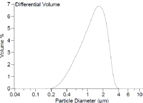
This parameter is of critical importance for the preparation of robocasting inks. The smaller are the particles, the smaller will be their aggregates, having a smaller probability that one of these might obstruct the nozzle. The particle size distribution was measured every time after the each ball milling step until obtaining results similar the ones presented in Fig. 10 and Table 4. Having relatively wide distribution makes it easier to prepare a highly concentrated suspension, since better packing behaviour might occur due to interparticle void filling of the smaller colloids can take place.11
European Master in Materials Science 27 Figure 10. Particle size distribution of CaP powder with 10%Sr calcined at 1000oC for 2h and ball
milled during 15+15+15min.
Table 4. Volume Statistics (Arithmetic) of particle sizes from 10%Sr CaP powder.
4.2. X-Ray diffraction characterization
The spectrums generated from the raw HA powders in the three compositions were very similar between each other and to those obtained from calcined powders at 400oC, 600oC and 700oC showing only the same crystalline HA phase. A first appearance of β-TCP phase occurred at the spectrums from doped powders calcined at 800oC, while the pure 0%Sr powder calcined at the same temperature had no substantial changes. These first β-TCP peaks had higher intensity in the 10%Sr powder compositionn. At 900oC the 0%Sr powder presented its first β-TCP peaks, having a very similar spectrum than the 5%Sr powder that had no remarkable
European Master in Materials Science 28
changes, while the 10%Sr powder continue developing its β-TCP phase. At 1000oC the three compositions increased the number and intensity of their peaks, meaning that they improve the crystallinity of both phases while the maximums where moved from the left side to the centre of the spectrum. After comparing all the mentionedXRD results, the influence of strontium on the enhancement of β-TCP phase is more than evident. The results from the powders calcined at 1000 oC are shown on Fig.11.
Figure 11. X-rays results from powders calcined at 1000oC.
4.3 Rheological Measurements
4.3.1. Viscometry mode
The different possible types of flow behaviorthat can be observed when performing tests in the viscometry mode (under steady shear) depending on suspension composition and stability are illustrated on Fig. 12. The apparent viscosity (ƞ) is related to the applied shear stress (𝛕) and shear rate (Ɣ) by the expression 𝛕 =ƞƔ. 28
20 25 30 35 40 45 50 55 60
In
tensi
ty
(a
.u.
)
2 theta (o) HA β-TCP 10%Sr 5%Sr 0%SrEuropean Master in Materials Science 29 Figure 12. Types of rheological behaviour exhibited by colloidal dispersions: (a) Newtonian flow; (b)
shear thinning; (c) shear thickening; (d) Bingham plastic; and (e) pseudoplastic with a yield stress.28
The results from the rheological measurements performed on the viscometry mode to the highly concentrated suspensions (60vol%of solid content) with increasing contents of dispersant are shown in Fig. 13. If we compare the curves with those from Fig.12, it is easy to identify that the suspensions present a pseudoplastic or shear-thinning behaviour, meaning that the viscosity decreases along with the shear rate, while the shear stress does the opposite.Increasing the amount of Targon from 0.5- 1.0wt% induced adecrement in the viscosity of the suspensions, adding more than this quantity leads to a raise of the viscosity. So, for the purpose of making highly concentrated suspensions, the lowest viscosity must be achieved.
The rheological parameters monitored at suspensions with 55vol% solid content, 1wt% of dispersant and increasing quantities of HMC are presented in Fig.14. The curves also present a shear thinning behaviour, although not so well defined as those in Fig.13. The more stable trajectory is presented with 0.5wt% of HMC, while the other three showed certain drops along the shear rate. Also, the consistency of the other three suspensions presented several lumps, thus when mixing with the gelifying agent, extremely aggregated pastes (unable to flow) were obtained. So the right
European Master in Materials Science 30
amount in order to cause an ideal reaction in addition with PE was fixed at 0.5wt% for HMC, PVP and a mixture of HMC+PVP (0.25%+0.25%).
Figure 13.60vol% 0%Sr CaP suspensions with different concentrations of Targon (T)
Figure 14.CaP suspensions 55vol% 0%Sr 1wt%T with increasing amounts of HMC.
In Fig. 15, logaritmic curves for the measurements performed with the fixed 0.5wt% quantity for the three viscosifying additives were compared in order to know their effects before the addition of the gelifying agent. The weakest of the three was PVP, followed by the mixture HMC-PVP although not in the middle range as it may be
European Master in Materials Science 31
thought, and finally HMC displays a substantial increase on the viscosity of the suspensions.
Figure 15.Comparison of the viscosifying effect of HMC, PVP and HMC+PVP
The effect of strontium on the flow behaviour of the robocasting inks can be inferred looking at the profiles from Fig.16. With the same ammounts of additives in the suspension (1wt%T, 0.5wt%PVP, 0.4wt%PEI), the 0%Sr suspension presents higher viscosity than both Sr doped inks along all the shear rate. The 5%Sr and 10Sr% inks traced very similar trayectories that intersect each other several times.
The graph in Fig. 17 shows the maximum added amounts of gelifying agent (PEI) among different combinations of suspensions tested. Obviously, the viscosifying additive employed was PVP since it is the weakest and allows to add more gelifier. The suspensions had 1wt% of Targon, 0.5wt%PVP and the following quantities of PEI: 0.4wt% for 0%Sr, 0.6wt%for 5%Sr, and 0.8wt% for 10%Sr. All the suspensions presented almost the same consistency at the time third stage of the ink preparation.
European Master in Materials Science 32 Figure 16.Effect of the strontium content on the suspension behaviour
Figure 17. Maximum values of PEI added to the CaP inks
4.3.2 Oscillatory mode
Structural information (liquid, gel, solid) can be inferred from the results of the frequency sweeps at a given stress (or strain) performed on the CaP suspensions. In Fig. 18, the models for the three possible types of response that can be obtained from such tests are illustrated. A liquid-like response is observed when G”>G’ along the entire frequency spectrum, these vary as w and w2 , respectively, as w→0. A gellike response is observed when G’and G”vary as wj, where j = 0.3 – 0.7, depending on the
European Master in Materials Science 33
system. A solid-like response is observed when G’> G”along the frequency spectrum, where G’is independent of frequency as w→0.28
Figure 18.Schematic representation of oscillatory behaviour as a function of frequency for (A) liquid,
(B) gel, and (C) solid response.28
On Fig. 19 are shown the results from oscillatory sweeps performed at samples from the three different compositions previous to the addition of the gelifying agent (0%PEI). The 0%Sr suspension presented a higher elastic response compared to those obtained from the doped inks. Also, former shows a more pronounced rheo-viscosifying behaviour than the strontium compositions. This means that by increasing the frequency (flow rate) the inks present a more viscous consistence. For the three different suspensions, the elastic modulus (G’) stays relatively stable along the frequency sweep, while the viscous modulus (G”) presents slopes which are more tilted at frequencies below 1Hz. The previous statements confirm that the suspensions present a solid-like response in all the oscillatory results. This is mainly due to the high solid particles concentrations on the inks, higher than fifty volume percent. On the results from Fig. 20, the suspensions were added with 0.4wt% amount of PEI. As expected, the three inks continue presenting a solid-like response but at much higher scale, meaning that the valuesfor both modulus are substancially bigger, specially for the viscous one. Another change is that the elastic modulus shows slight slopes in the three cases. The0%Sr suspensions has a much greater rheo-viscosifying behaviour compared to the doped suspensions and to its previous result with no PEI addition. The 10%Sr ink showed a higher viscous modulus during the entire oscillatory frequency sweep.
European Master in Materials Science 34 Figure 19.Oscillatory frequency sweep results from inks with no addition of PEI
Figure 20. Oscillatory frequency sweep results from inks with 0.4wt% PEI
4.4 Robocasting of scaffolds
The robotic depositions were performed using three different inks (0%Sr-55vol%-0.5wt%PVP-0.4wt%PEI, 5%Sr-50vol%-0.5wt%PVP-0.6wt%PEI, and 10%Sr-50vol%-0.5wt%PVP-0.8wt%PEI) and three different nozzle tips (red-conical-plastic-250µm, orange-cylindrical-metallic-330µm, and blue-conical-plastic-410µm). The geometry and diameter of the nozzle tip is a critical factor that may cause failure of the ink
European Master in Materials Science 35
deposition. For instance, only one sample was achieved to be successfully printed through the smaller red nozzle with the 0%Sr ink. It had a cubic architecture (1cm3) with tetragonal mesh, outer support ring, rod diameter d=250µm, horizontal center to center spacing between rods s=500µm, vertical spacing between layers s=200µm. The main problem source seems to be the generation of bubbles within the inks, which are really difficult to remove, thus they are trapped in the syringe where they flow along with the ink until they get trapped at the nozzle because their superficial tension is higher than the injecting pressure of the deposition device. So when this happens, either the process may be completely interrupted and the nozzle tip must be removed, or the process may suffer a delay on the injection while the pressure is overcome and the bubble extruded, but this causes a dramatic increase on the flow thus imperfections on the template. Issues of this kind where experienced when using the orange nozzle, although in leaser degree than with the previous. The blue nozzle was optimal since its relatively big diameter enabled the bubbles to be easily ejected without causing imperfections.
A total number of twenty samples were produce by robocasting, four pairs of identical scaffolds and sixteen with different characteristics (Table 5). The spanning features had different shapes and sizes up to the range of a few milimiters of separation between rods. This is difficult to achieve and requires very good physical properties of the ink, since flow is usually aided by the traction of the filament with the substrate or with the underlying rods, so when this aid is absent the filament must have really good characteristics in order to flow by itself and to maintain its shape without bending once it is linked.
The picture on Fig. 21 shows the sixteen different types of scaffolds fabricated. Sample 1 was done using a red nozzle (d=250µm), samples 4,5,7,8 and 9 were done using an orange nozzle (d=330 µm). The remaining samples 2,3,6 and 10-16 were fabricated with a blue nozzle (d=410 µm). The scaffolds with squared layers have one centimeter per side and different heights due to different number of printed layers.
European Master in Materials Science 36
Some of them may look the same but may differ either on having a supporting external ring or different ink composition. The cylindrical architectures have a diameter of 1.5cm with internal holes diameters of 3mm and 6mm. The triangular scaffold has 1cm on the base and it is 1.8cm long. The shrinkage after sintering was around 15% compared to the initial volume for all the specimens.
Table 5. Specifications of the different robocasted specimens
# Ink Nozzle Shape Size
(mm) Mesh Supporting ring D (μm) S (μm) H (μm)
1 0%Sr-55vol% Red Cubic L=10 Tetragonal Yes 250 500 200
2 0%Sr-55vol% Blue Cubic L=10 Tetragonal Yes 410 820 320
3 0%Sr-55vol% Blue Cubic L=10 Tetragonal No 410 820 320
4 0%Sr-55vol% Orange Cubic L=10 Tetragonal Yes 330 660 260
5 0%Sr-55vol% Orange Cubic L=10 Tetragonal No 330 660 260
6 5%Sr-50vol% Blue Cubic L=10 Tetragonal Yes 410 820 320
7 5%Sr-50vol% Orange Cubic L=10 Tetragonal Yes 330 660 260
8 5%Sr-50vol% Orange Cubic L=10 Tetragonal Yes 330 990 260
9 5%Sr-50vol% Orange Cubic L=10 Tetragonal No 330 990 260
10 10%Sr-50vol% Blue Cubic L=10 Tetragonal Yes 410 820 320
11 10%Sr-50vol% Blue Triangular b=10 h=18
Tetragonal Yes 410 820 320
12 10%Sr-50vol% Blue Cubic L=10 Tetragonal Yes 410 1230 320
13 10%Sr-50vol% Blue Cilindrical D=15 Tetragonal No 410 820 320
14 10%Sr-50vol% Blue Cilindrical D=15 d=6
Radial No 410 820 320
15 10%Sr-50vol% Blue Cilindrical D=15 d=1
Radial No 410 820 320
16 10%Sr-50vol% Blue Cilindrical D=15 d=3
European Master in Materials Science 37 Figure 21. CaP scaffolds fabricated by robocasting