A Multi-branch Linear Amplification with
Nonlinear Components Technique
Jo˜ao Guerreiro
(1,2), Rui Dinis
(1,3), Paulo Montezuma
(1,3), Jo˜ao P. Oliveira
(3), M´ario Silva
(1,2) (1)IT, Instituto de Telecomunicac¸˜oes, Lisboa, Portugal.
(2)
UAL, Universidade Aut´onoma de Lisboa, Lisboa, Portugal.
(3)FCT, Universidade Nova de Lisboa, Monte de Caparica, Portugal.
Abstract—Single carrier modulations with high order constel-lations or orthogonal frequency division multiplexing (OFDM) modulations can be employed to obtain spectrally efficient communications. However, such modulations lead to signals with large envelope variations, where the amplification is challenging and usually energy-inefficient. The linear amplification with non-linear components (LINC) makes use of two efficient, nonnon-linear power amplifiers for an efficient amplification. In this work, we propose the multi-branch LINC (MB-LINC) technique, which allows the use of highly-efficient nonlinear amplifiers without increasing the nonlinear distortion effects, even if the amplifiers are not balanced1.
Index Terms—OFDM, PAPR, amplification, energy efficiency.
I. INTRODUCTION
Two of the most important aspects of wireless communica-tion systems are the energy and the spectral efficiency. Achiev-ing these two goals simultaneously is a very challengAchiev-ing task, specially when considering spectrally efficient modulations such as single carrier modulations with high order constella-tions or orthogonal frequency division multiplexing (OFDM) modulations [1], which are known to exhibit large peak-to-average power ratio (PAPR). To avoid nonlinear distortion effects, which are more critical for larger constellations, and to avoid out-of-band emissions and maintain the high spectral efficiency of such modulations, one should consider quasi-linear power amplifiers (PA). However, these amplifiers have low amplification efficiency and require high output back-off to accommodate the high PAPR of the input signals in the linear amplification region, which reduces further more the energy efficiency. Thorough the last years, many techniques that aim to reduce the PAPR prior to the amplification and improve the amplification efficiency have been proposed [2], [3]. Besides these PAPR reducing techniques, another solution for the amplification issues associated with spectral efficient transmission schemes is the linear amplification with nonlinear components (LINC) technique [4], where two simple and 1This work is supported by the European Regional Development Fund
(FEDER), through the Competitiveness and Internationalization Operational Program (COMPETE 2020) of the Portugal 2020 framework, Regional OP Centro (POCI-01-0145-FEDER-030588), Regional OP Lisboa (Lisboa-01-0145-FEDER-03058) and by FCT/MEC through national funds, under Project PES3N (SAICT-45-2017-02) and Instituto de Telecomunicac¸˜oes project UID/EEA/50008/2013.
highly efficient, nonlinear amplifiers (such as the ones of class E, F [5] or D [6]) are combined to obtain an efficient amplification. The unavoidable losses associated with the combination process of the LINC can be compensated by the fact that we can employ efficient, grossly nonlinear power amplifiers, with each amplifier driven by a signal with a quarter of the required power that would be necessary if a single amplifier was employed.
In terms of monolithic implementation, namely using a low cost CMOS technology, the downscaling evolution of the technology nodes verified in the past decades has enabled the integration of an increasing number functionalities in the same integrated circuit (IC) die, in a system on chip (SoC) architecture [7]. However, this size downscaling is followed by a reduction of the maximum supply voltage (Vsupply) that
can be applied to the IC [8], thus imposing serious limitations on the maximum output power (related with V2
supply) that can
be extracted from one single traditional RF Power Amplifier (namely, using a class A biasing scheme). To overcome it, parallel circuit techniques [9] can be used to combine the power of a set of multiple RF power amplifier branches operating, each one, at a low supply voltage.
In this work, we propose the multi-branch LINC (MB-LINC) technique where P nonlinear amplifiers are consid-ered to achieve an efficient amplification and at the same contributing to improve the total output RF power. Therefore, the power consumption of each amplifier can be made very low by increasing P . One of the major problems of conven-tional LINC is the nonlinear distortion effects caused by the imbalances of the amplifiers’ gain. In this work, it is shown that the robustness of MB-LINC to nonlinear distortion effects regarding mismatches in the amplifiers’ gain is similar to that of conventional, two-branch LINC.
This work is organized as follows: in Sec. II a brief review of conventional LINC schemes is presented. Sec. III is dedicated to the explanation of the proposed MB-LINC amplification scheme. In Sec. IV it is shown how the nonlinear distortion effects associated to the MB-LINC can be evaluated and a set of results regarding the power spectral density (PSD) and the self-to-interference (SIR) of the resultant MB-LINC signals are presented. Sec. V shows the conclusions of this paper.
II. CONVENTIONALLINC
Let us start by considering a given bandpass signal written in the form
s(bp)(t) = r(t) cos(2⇡fct + (t)), (1)
where fc represents the carrier frequency. Its
complex-envelope, s(t) can be written as
s(t) = r(t) exp (j (t)) , (2)
where r(t) and (t) represent the absolute value and phase, respectively. In conventional LINC techniques, the signal s(t) is separated into N = 2 constant-envelope and out-phasing signals, s1(t) and s2(t). Without loss of generalization, we
will illustrate the LINC concept for the specific case where the envelope is real-valued i.e., (t) = 0, which means that s(t) = r(t) (the extension to other cases is straightforward).
Fig. 1 represents the conventional LINC decomposition under two components that lie in a circle with radius RM/2.
From the vectorial representation of the figure, we can define
R
M RM 2 ✓ 2s
s
2s
1 ✓ 2Fig. 1. Vectorial representation of the conventional LINC decomposition.
the two LINC components as s1(t) = RM 2 exp ✓ j✓(t) 2 ◆ , (3) and s2(t) = RM 2 exp ✓ j✓(t) 2 ◆ . (4)
Since these two signals have constant-envelope, they can be efficiently amplified with nonlinear power amplifiers. When the amplifiers’ gain are equal, the combination of the two LINC components produce a scaled replica of s(t), eventually clipped to a level RM. In fact, the combination of the two
signals can be generally thought as a clipped, nonlinearly distorted version of s(t), since the maximum amplitude of the combined signal is limited to RM (which is a value obtained
when ✓/2 = 0). Under these conditions, the LINC process can be modeled as a bandpass memoryless nonlinearity charac-terized by the corresponding amplitude modulation/amplitude
modulation (AM-AM) and amplitude modulation/phase mod-ulation (AM-PM) conversion functions [10]. The complex envelope of the nonlinearly distorted signal can be written as y(t) = A (r(t)) exp (j( (t) + ⇥(r(t))) , (5) where A(r(t)) and ⇥(r(t)) represent the AM-AM and the AM-PM conversion functions, respectively. For the specific case of an envelope clipping, we have ⇥(r(t)) = 0 and
A(r(t)) = ⇢
r(t), r(t) RM
RM, r(t) > RM, (6)
where RM denotes the clipping level. Still considering the
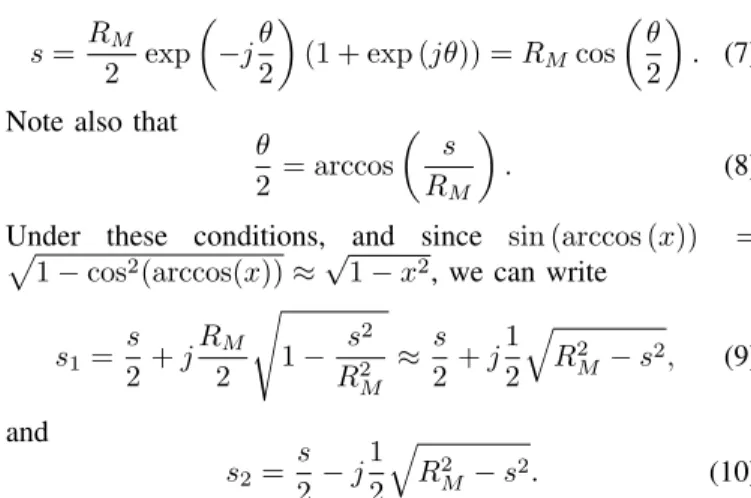
geometry represented in Fig. 1, we can write, omitting the time dependence, s = RM 2 exp ✓ j✓ 2 ◆ (1 + exp (j✓)) = RMcos ✓ ✓ 2 ◆ . (7) Note also that
✓ 2 = arccos ✓ s RM ◆ . (8)
Under these conditions, and since sin (arccos (x)) = p
1 cos2(arccos(x))⇡p1 x2, we can write
s1= s 2 + j RM 2 s 1 s 2 R2 M ⇡ s 2 + j 1 2 q R2 M s2, (9) and s2= s 2 j 1 2 q R2 M s2. (10)
Besides this “global nonlinearity” of the LINC process, which is an envelop clipping, we can define a bandpass memoryless nonlinearity for the pth branch (where p can be either 1 or 2, depending on the specific amplification branch), whose the AM/PM conversion function is defined as
⇥p(r) = ( 1)parccos ✓ r RM ◆ , (11)
and the AM/AM conversion function is Ap(r) = R2M.
III. MULTI-BRANCHLINC
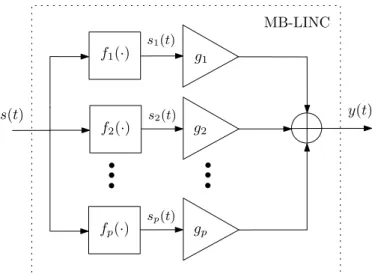
In the following, we propose the MB-LINC transmitter, which generalizes the LINC concept by considering up to P amplification branches. In this technique, the signal s(t) is divided into P components that are amplified separately through a set of nonlinear amplifiers, as is shown. in Fig. 2. As in conventional LINC, when there are P amplifying branches, the vectorial representation of the different LINC components is such that their sum produces the envelope at a given time instant.
Fig. 3 shows the vectorial representation of the MB-LINC components when P is even (P = 4) and when P is odd (P = 5). From this figure, it can be noted that, regardless of the value of P , the pth signal (i.e., the signal associated with the pth amplifying branch) of the MB-LINC decomposition is defined as sp= RM P exp ✓ j✓ 2(2p P 1) ◆ . (12)
f1(·) s(t) fp(·) g1 gp MB-LINC y(t) s1(t) sp(t) f2(·) g2 s2(t)
Fig. 2. Vectorial representation of the conventional LINC decomposition.
RM RM 5 s s5 s1 a) s2 s4 RM RM 4 s s1 a) s2 s3 ✓ s4 ✓ s3
Fig. 3. Vectorial representation of the MB-LINC decomposition when P = 5 (a) and when P = 4 (b).
Therefore, the complex envelope of the MB-LINC output, given by the combination of the P signals, can be written as s = P X p=1 sp = P X p=1 RM P exp ✓ j✓ 2(2p P 1) ◆ = RM P exp ✓ j✓ 2(P 1) ◆1 exp(j✓P ) 1 exp(j✓) . (13)
Under these conditions, we may write s = RM P sin P✓ 2 sin ✓2 = RMfP(✓), (14) with fP(✓) = sin P✓2 P sin ✓ 2 . (15)
It should be noted that, if P = 2, we have the conventional two branch LINC, i.e.,
s =RM 2 2 sin ✓2 cos ✓2 sin ✓ 2 = RMcos ✓ ✓ 2 ◆ , (16) as obtained in (7).
Fig. 4 shows the envelope of a given OFDM signal before and after the LINC amplification scheme. The values of the envelope at the points A, B and C can be vectorial built by the LINC components represented in the Fig. 5.
t 50 100 150 200 250 300 350 400 450 500 0 0.5 1 1.5 2 2.5 3 3.5
After LINC - y(t) Before LINC - s(t)
B
A
C
Fig. 4. Envelope of a given OFDM signal before and after the LINC amplification scheme. RM RM 4 s s2 s1 RM RM 4 s s3 s1 RM RM 4 s s4 s1 A B C s3 s4 s2 s4 s2 s3
Fig. 5. Vectorial representation of the MB-LINC components with P = 4 for the three envelope values identified in Fig. 5: almost 0 (A), clipped to RM (B) and lower than RM (C).
Clearly, when the envelope is almost 0, the phase of the LINC components approaches ±⇡/2. On the other hand, when the envelope is clipped, the LINC components are aligned with the direction of s, yielding the maximum output value. The case C illustrates a situation where s < RM.
In general, for a given P , ✓ is defined as ✓ = fP1
✓ r
RM
◆
. (17)
Therefore, we can rewrite the output signal associated to the pth branch as sp=RM P exp ✓ j ✓ fP1 ✓ r RM ◆ 2p P 1 2 ◆◆ . (18)
Thus, taking into account (12), one can define the AM/PM and AM/AM conversion functions associated to the pth branch as
⇥p(r) = fP1
✓ r
RM
◆2p P 1
and
Ap(r) = RM
P . (20)
It is well-known that imbalances in the complex gains of LINC’s amplifiers lead to performance degradation [12], [13]. In that context, one could expect the situation to be more serious with MB-LINC, since there are more amplifying branches. To study the impact of these imbalances on the MB-LINC signal, let us consider the combined signal after amplification, which is given by
s = P X p=1 gpRM P exp ✓ j ✓ fP1 ✓ r RM ◆ 2p P 1 2 ◆◆ , (21) where gpis the complex gain associated with the pth amplifier,
defined as gp = 1 + "g, with "g being a complex-valued
deviation whose the real and imaginary parts have variance 2 ",
i.e., "g⇠ CN (0, 2 "2). Naturally, when "= 0, the amplifiers
have equal gains and (21) turns into (16). On the other hand, when " > 0, the magnitude of nonlinear distortion
effects associated with the MB-LINC signal will depend on the combination of the gains of the different amplifiers.
IV. NONLINEARDISTORTIONEFFECTS
By taking advantage of the Gaussian nature of OFDM signals with a large number of subcarriers N, the PSD of their nonlinearly distorted version can be obtained through their autocorrelation, Ry(n), that is itself a function of the
input signals’ autocorrelation, Rs(n), and of the power
as-sociated to the different intermodulation products (IMPs) at the nonlinearity output. The autocorrelation of a nonlinearly distorted OFDM signal can be computed as [14]
Ry(n) = +1 X =0 P2 +1 Rs(n) +1(R⇤s(n)) 2(2 +1) , (22)
where is the standard deviation of the input signal and P2 +1
is the power associated with the IMP of order 2 + 1. The PSD of the nonlinearly distorted signal, Gy(k), is given by
DFT(Ry(n)). Moreover, from the Bussgang’s theorem [15],
we can express the nonlinearly distorted signal as the sum of two components. Under these conditions, the PSD of MB-LINC signals can be written as
Gy(k) =|↵|2Gs(k) + Gd(k), (23)
where ↵ is a scale factor given by the scaled cross-correlation between the OFDM signal and its nonlinear distorted version, and Gs(k) and Gd(k) are the PSDs of the input signal and
nonlinear distortion term, respectively.
Fig. 6 shows the normalized PSD of the nonlinear distortion term, gd(k) = Gd(k)/ max(|↵|2Gs(k)), considering different
values of P , "= 0and RM/ = 1.5(due to the symmetry
associated to the different amplification branches, only (P 1)/2+1PSDs are shown). From the figure, it can be noted that although the PSD of the nonlinear distortion term associated to the different branches can vary, the PSD associated to the combined signal is the same, regardless of P . To have an
−2 −1 0 1 2 −35 −30 −25 −20 −15 −10 −5 0 5 k/N gd (k )[ d B ] −2 −1 0 1 2 −35 −30 −25 −20 −15 −10 −5 0 5 k/N gd (k )[ d B ] P = 5 P = 9 : Branch · · · : Combined
Fig. 6. Normalized PSD of the nonlinear distortion term associated to the different MB-LINC branches.
insight on the performance penalty associated to the nonlinear distortion, we can define the SIR for a the kth subcarrier as
SIRk =|↵| 2G
s(k)
Gd(k) . (24)
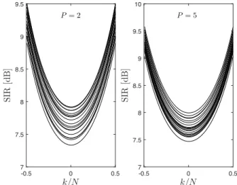
Fig. 7 shows the evolution of SIRk considering an MB-LINC
transmitter with sM/ = 1.0, different values of P and " = 0.05. From the figure, it can be noted that although
k/N -0.5 0 0.5 SI R [dB ] 7 7.5 8 8.5 9 9.5 k/N -0.5 0 0.5 SI R [dB ] 7 7.5 8 8.5 9 9.5 10 P = 2 P = 5
Fig. 7. Evolution of SIRkconsidering an MB-LINC transmitter with different
values of P and "= 0.05.
there are variations on the SIR for different gain combinations, the magnitude of these variations is similar. Therefore, the use P > 2 does not increase the nonlinear distortion effects comparatively to the conventional LINC, where P = 2.
V. CONCLUSIONS
In this work we propose the MB-LINC technique, which generalizes the conventional LINC. It is shown that, although
each amplifier can work with low power signals, the spectral characteristics of the combined signal does not change rela-tively to the conventional LINC techniques, even when there are imbalances in the amplifiers’ gain.
REFERENCES
[1] L. Cimini, “Analysis and simulation of a digital mobile channel using orthogonal frequency division multiplexing,” IEEE Trans. Commun., vol. 33, no. 7, pp. 665–675, Aug. 1985.
[2] Y. Rahmatallah and S. Mohan, “Peak-to-average power ratio reduction in OFDM systems: a survey and taxonomy”, IEEE Communication Surveys and Tutorials, vol. 15, no. 4, pp. 1567–1592, Mar. 2013.
[3] J. Han and H. Lee, “An overview of peak-to-average power ratio reduction techniques for multicarrier transmission”, IEEE Wireless Commun., vol. 12, no. 2, pp. 56–65, Apr. 2005.
[4] D. Cox, “Linear amplification with nonlinear components,’ IEEE Trans. Commun., vol. 22, no. 12, pp. 1942–1945, Dec. 1974.
[5] A. Banerjee, R. Hezar, L. Ding, N. Schemm and B. Haroun,“A 29.5 dBm class-E outphasing RF power amplifier with performance enhancement circuits in 45nm CMOS,“ 40th IEEE European Solid State Circuits Conference, Venice, pp. 467–470, Sept. 2014.
[6] H. Xu, Y. Palaskas, A. Ravi, M. Sajadieh, M. A. El-Tanani and K. Soumyanath,“A Flip-Chip-Packaged 25.3 dBm Class-D Outphasing Power Amplifier in 32 nm CMOS for WLAN Application,“ IEEE Journal of Solid-State Circuits, vol. 46, no. 7, pp. 1596–1605, Jul. 2011. [7] B. Francois and P. Reynaert:“A Fully Integrated Watt-Level Linear
900-MHz CMOS RF Power Amplifier for LTE-Applications,“IEEE Trans. on Microwave Theory and Techniques, vol. 60, no. 6, pp. 1878–1885, June 2012.
[8] A. Banerjee, R. Hezar and L. Ding,“Efficiency improvement techniques for RF power amplifiers in deep submicron CMOS,“ IEEE Custom Integrated Circuits Conference, San Jose, CA, Sept. 2015.
[9] S. Kang, D. Baek and S. Hong,“A 5-GHz WLAN RF CMOS Power Am-plifier With a Parallel-Cascoded Configuration and an Active Feedback Linearizer,“ IEEE Trans. on Microwave Theory and Techniques, vol. 65, no. 9, pp. 3230–3244, Sept. 2017.
[10] A. Kaye, D. George and M. Eric, “Analysis and compensation of bandpass nonlinearities for communications,” IEEE Trans. Commun., vol. 20, no. 5, pp. 965–972, Oct. 1972.
[11] R. Dinis, and A. Gusm˜ao, “Nonlinear signal processing schemes for OFDM modulations within conventional or LINC transmitter structures,’ European Trans. on Telecomm., vol. 19, no. 3, pp. 257–271, Jan. 2008. [12] J. Guerreiro, R. Dinis and P. Montezuma, “A simple method for the
analytical characterization of OFDM schemes with LINC transmitter structures,” ISWCS’15, Brussels, Belgium, Aug. 2015.
[13] F. Casadevall, and A. Valdovinos “Performance analysis of QAM modulations applied to the LINC transmitter,” IEEE Trans. Veh. Technol., vol. 42, no. 4, pp. 399–406, Nov. 1993.
[14] R. Dinis and A. Gusm˜ao, “A class of nonlinear signal processing schemes for bandwidth-efficient OFDM transmission with low envelope fluctuation,” IEEE Trans. Commun., vol. 52, no. 11, pp. 2009–2018, Nov. 2004
[15] H. Rowe: “Memoryless nonlinearities with Gaussian input: elementary results,” Bell System Tech. Journal, vol. 61, no. 7, pp. 1519–1526, Sept. 1982.