Appl. Sci. 2019, 9, 243; doi:10.3390/app9020243 www.mdpi.com/journal/applsci Article
Stochastic Vulnerability Assessment of Masonry
Structures: Concepts, Modeling and Restoration
Aspects
Panagiotis G. Asteris 1,*, Antonia Moropoulou 2, Athanasia D. Skentou 1, Maria Apostolopoulou 2, Amin Mohebkhah 3, Liborio Cavaleri 4, Hugo Rodrigues 5 and Humberto Varum 6
1 Computational Mechanics Laboratory, School of Pedagogical and Technological Education, Heraklion,
14121 Athens, Greece; [email protected]
2 Laboratory of Materials Science and Engineering, School of Chemical Engineering, National Technical
University of Athens, 15780 Athens, Greece; [email protected] (A.M.); [email protected] (M.A.)
3 Department of Structural Engineering, Malayer University, 65719-95863 Malayer, Iran;
4 Department of Civil, Environmental, Aerospace and Materials Engineering (DICAM), University of
Palermo, Viale delle Scienze, 90128 Palermo, Italy; [email protected]
5 RISCO, Department of Civil Engineering, Polytechnic Institute of Leiria, 2411-901 Leiria, Portugal;
6 Faculdade de Engenharia, Universidade do Porto, Departamento de Engenharia Civil, 4200-465 Porto,
Portugal; [email protected]
* Correspondence: [email protected]; Tel.: +30-210-2896-922
Received: 27 October 2018; Accepted: 30 December 2018; Published: 10 January 2019
Abstract: A methodology aiming to predict the vulnerability of masonry structures under seismic action is presented herein. Masonry structures, among which many are cultural heritage assets, present high vulnerability under earthquake. Reliable simulations of their response to seismic stresses are exceedingly difficult because of the complexity of the structural system and the anisotropic and brittle behavior of the masonry materials. Furthermore, the majority of the parameters involved in the problem such as the masonry material mechanical characteristics and earthquake loading characteristics have a stochastic-probabilistic nature. Within this framework, a detailed analytical methodological approach for assessing the seismic vulnerability of masonry historical and monumental structures is presented, taking into account the probabilistic nature of the input parameters by means of analytically determining fragility curves. The emerged methodology is presented in detail through application on theoretical and built cultural heritage real masonry structures.
Keywords: Artificial Neural Networks; damage index; failure criteria; fragility analysis; masonry structures; monuments; restoration mortars; seismic assessment; stochastic modeling
1. Introduction
Masonry corresponds to one of the most ancient building structure types. This explains the fact that the majority of monuments are masonry structures, meaning main building elements are joined together through the use of mortars. The main building elements could refer to stones or bricks or a combination of both and can have different geometries, ranging from orthogonal shaped elements of standardized dimensions to random shaped elements of different dimensions (rubble masonry). The inhomogeneous and anisotropic nature of this particular structure type, as well as that of the
materials comprising it, define to a great extent the seismic response of monumental buildings. In particular, a common characteristic of these structures is their high seismic vulnerability when subjected to earthquake stresses, which is attributed to the highly brittle behavior and relatively low tensile strength of the individual building materials comprising masonries. Historical masonry monumental buildings, for instance ancient masonry churches, are unique and cannot be reduced to any standard structural scheme: this makes the evaluation of their seismic reliability a very challenging task, because—in addition to the many uncertainties that are common to all existing structures—no statistics on their behavior are available [1–4]. The cultural, social and architectural values of historical buildings demand respect of their uniqueness and individual identity. Thus, any measures taken for their protection, aiming to decrease their vulnerability, must comply with the principles of reversibility and compatibility; reversibility of an intervention means that any conservation action implemented can be “undone” without any damaging alteration to the authentic structure and materials, while compatibility of the intervention means that the intervention and materials applied will not harm the authentic materials and structure in any way, i.e., provoke or intensify damaging chemical reactions, introduce soluble salts, prevent homogenous behavior regarding water transfer phenomena, cause aesthetic alteration, etc. Of course, it is difficult for an intervention, and especially a reinforcement intervention, to truly and fully abide with these two principles, however it is necessary to undertake all possible strain and measures in this direction in order to ensure that cultural heritage assets of the past are passed along to future generations with a promise of longevity for centuries to come. Thus, this obligation to protect cultural heritage assets creates the demand for the strict compliance of protection measures within the regulatory frameworks which govern these structures, on both national and international levels.
Already from the beginning of the previous century [5,6], regulatory frameworks regarding the protection of historical buildings were formulated and accepted, such as the guidelines given by the International Scientific Committee of the Analysis and Restoration of Structures of Architectural Heritage of ICOMOS in 2001, and in particular the ICOMOS Charter regarding the Principles for the Analysis, Conservation and Structural Restoration of Architectural Heritage (ISCARSAH Principle). This particular regulatory framework is based on the principles of research and documentation, authenticity and integrity, aesthetic harmony, least invasive interventions and reversibility, principles which are in accordance with the demands of the Athens and the Venice Charters, as well as with the principles established by Morton and Hume [7]. An additional prerequisite for the successful protection of these structures is related to the interdisciplinary approach, which should be adopted during the investigation and assessment of any repair scenario.
A prerequisite for the formulation of a reliable methodology to predict the seismic vulnerability of historical/monumental masonry structures is the successful simulation of the structural system, as well as of the materials comprising the masonry, through the formulation of appropriate analytical statutory laws. In this direction, however, the complex mechanical behavior of masonries, which is a multiphase material, is a serious obstacle. Furthermore, an additional and at the same time basic difficulty regarding the formulation of such a methodology is related to the probabilistic nature of the parameters influencing the behavior of masonry structures. Among these parameters are the values of the mechanical properties of the materials (due to the wide dispersion of these values regarding the whole of the structure or due to limitation regarding the accuracy of the measurements, related to the lack of sufficient accuracy of methods and instruments used, in addition to limitations imposed by monuments protection legislation regarding sampling). Additionally, the probabilistic nature of earthquakes, directly connected and influenced by a large number of parameters, must be taken into account. Due to the high uncertainty of the parameters influencing the behavior of masonry structures, the assessment of their vulnerability cannot be conducted in terms of a deterministic approach [8–23]. To the contrary, a probabilistic approach would be more appropriate, in order to be applied in cases where the response of the structure is evaluated and compared with limit states, such as specific limit values of response directly interlinked with structural damages.
In the framework of the above limitations and issues of specific consideration, this study presents an analytical methodology for the evaluation of seismic vulnerability of masonry structures, taking into account the probabilistic nature of the parameters involved through the development of analytical fragility curves.
2. Need for Research
Despite the plethora of research work conducted and published in the last two decades (Figure 1), modeling and assessment of the seismic vulnerability of masonry structures remains an open issue and, at the same time, a challenge for the practicing civil engineer.
Figure 1. Evolution of number of publications concerning the masonry materials and structures
based on Scopus bibliographic database (28 December 2018).
Masonry structures are an important part of today’s built environment, as it is one of the oldest building systems known to humanity. It is believed to have been in use for over 6000 years and is still in use today in several regions globally. Specifically, in addition to the plethora of important historical structures and monuments which are masonry structures and must be preserved for future generations due to their historical importance, masonry is the most widely used construction type, not only in poverty-stricken countries, due to its low cost compared to the other modern materials, but also in developed countries, due to the aesthetic value that it provides when used in modern constructions. However, it should be highlighted that a common characteristic of all masonry structures is their high seismic vulnerability when subjected to seismic stresses. This is due to the fact that masonry structures are of a brittle and anisotropic nature and, subsequently, each one depicts a distinct brittle and anisotropic behavior. Indeed, masonry is a composite “material” that exhibits distinct directional properties, mainly because the mortar joints act as planes of weakness.
The modeling of the structural behavior, as well as the mechanical characteristics of masonry structures, and the materials comprising it, is still an open issue to this day. The importance of the issue, in addition to the historical values of many masonry structures and of course the safety issues involved, is also linked with economic factors, as approximately 80% of the structural cost from earthquakes is attributable to damage of masonry walls and to the consequent damage of doors, windows, and electrical and hydraulic installations [24]. The intense computational complexity
which accompanies such a complex building system is a main problem that must be overcome to successfully accomplish their modeling and assessment in relation to seismic vulnerability and thus successfully protect them by implementing various reinforcement action. For the special case of monumental masonry structures, additional necessary restrictions based on legislations for monument protection, aiming to preserve cultural, artistic, and historical values of the structure, as stated in a series of scientific Charters (e.g., the Athens Charter (1931) [5], the Venice Charter (1964) [6], etc.), make the process of modeling and restoration even more complex.
In addition to the above difficulties, one must also consider the probabilistic nature of earthquakes, which is directly connected and influenced by a significant number of parameters. Thus, due to the high uncertainty of the parameters influencing the behavior of masonry structures, the assessment of their vulnerability cannot be conducted in terms of a deterministic approach. To the contrary, as presented and validated in the following sections, it is suggested to follow a probabilistic approach, which should be applied in cases where the response of the structure is evaluated and compared with limit states, such as specific limit values of response directly interlinked with structural damages.
Taking into account the intensely anisotropic nature and behavior of masonry, it would not be an exaggeration to state that masonry material is the mother of all materials (indeed, the word material derives from μήτηρ in ancient Greek (méeteer), mater in Latin and matar in ancient Hindu, which are all words for “mother”). In fact, the authors believe that it would be extremely valuable for lectures in mechanics and material strength, aiming to educate young engineers, to be orientated to masonry materials instead of only concrete and steel, as is usual practice today. Although reinforced concrete is the choice material of today, masonry still comprises a great percentage of existing buildings and incorporates a complexity in its analysis which can be of high educational value.
3. Proposed Methodology
Taking into account the principles and guidelines of ICOMOS, as well as the results of relative research projects [25–46], a specific methodology has been developed in relation to the restoration of historical masonry structures. The flow chart of the proposed methodology is presented in Figure 2. The proposed methodology is formulated by discrete steps. In particular, it includes the evaluation and/or determination of the mechanical properties of the materials, the simulation of the structural system and of the forces, the analysis of the structure regarding specific stresses, the determination of the failure areas of the structure and the respective damage indices, regarding both the model of the structure in its current condition, as well as for the models of the structure in relation to different repair scenarios. Finally, based on the damage indices, fragility curves are developed, which, as illustrated in the following section, contribute to the quantified assessment of the structure’s vulnerability in its current condition, and to the assessment of the effectiveness of different repair scenarios.
In the framework of the proposed methodology, the following eight distinct steps that also define the structure of the present work are included.
Figure 2. Flow chart of the proposed methodology.
3.1. Step 1: Reliable Reconstruction of Structure
The successful modeling of an existing masonry structure is a prerequisite for the reliable seismic vulnerability assessment and for the correct decision-making during a restoration process. To achieve that, detailed data able to represent not only the whole geometry of the structure but also the geometry and the mechanical characteristics of the constitutive materials are necessary.
Furthermore, the mathematical reconstruction is crucial to include the interconnections of materials. Connections of perpendicular walls or of walls and floors should be thoroughly investigated.
The need for detailed reconstruction of an existing structure through reliable numerical models is greater in the case of a historical masonry building. The great difference between a numerical model for the design of a new building and a numerical model of a monumental masonry structure is that in the first case the numerical model represents the reality to which the new structure (still virtual) will have to resemble, whereas in the analysis of a historical building, the reality is represented by the building itself, and the virtual model must be able to describe this singular reality. For this reason, the accurate identification of reality in all its aspects (geometry, history, traumas, deformations, materials, deteriorations, etc.) constitutes the preliminary and fundamental phase of structural analysis: only the complete knowledge of reality and the agreement between the model results and the reality itself will be able to validate the structural analysis.
In light of the above the interdisciplinary approach, a basic requirement according to ICOMOS [5,6] as mentioned in the Introduction, becomes imperative and should be adopted during all main phases comprising the proposed methodology about the stochastic vulnerability assessment of masonry historical structures. Such an interdisciplinary approach needs a close cooperation of different experts such as architects, civil engineers, chemical engineers, historians, archeologists and specialists in digital reconstruction. The participation of historians and archeologists in the research team is essential for conservation and restoration of historic buildings and their role is to detect and preserve the values of the monument, highlighting its importance. Furthermore, its participation is crucial for the documentation of the structure including aspects such as the history of the building, its chronology and the history of constructive techniques. Information concerning historical constructive issues could be obtained from documentary sources, such as ancient drawings and descriptions or historical studies [47,48] and can be supported by scientific data, as produced by the other disciplines involved [49]. In addition, the participation of specialists in the digital reconstruction is of great interest for a reliable reconstruction of such structures. In the last two decades, image-based techniques and terrestrial laser scanning have proved to be suitable tools for the digital reconstruction of such complex structures producing three dimensional models of the structure [50,51]. The production of the high-resolution 3-D model enables the extraction of the necessary conventional 2-D information.
It is common practice for researchers to focus on the detailed reconstruction of the monumental structure but at the same time give little attention to the reconstruction of the subsoil and the foundation. To this end, several data acquisition techniques such as the ground penetrating radar [52] are available for the reliable reconstruction of the subsoil and the foundation of the structure. This technique has been used with great success in the Holy Aedicule’s rehabilitation of the Holy Sepulchre in Jerusalem [53]. Interpretation of the measurements revealed the position of the rock, remnants of the initial cave, which, according to tradition, is the original site of Christ’s burial and resurrection, thus providing information regarding the underground features as well as details regarding the internal phases of the structure’s masonry.
3.2. Step 2: Materials Characterization and Mechanical Characteristics
Among the crucial tasks for a successful modeling of masonry structures is that referring to the characterization (physical and mechanical properties) of the building materials. Furthermore, in the case of monumental masonry structures, both the characterization and the properties of materials such as stones, bricks and mortars are critical for the structural modeling of the structure. When dealing with historic masonries, the researcher must keep in mind that the structure in its current state, as well as the materials comprising it, are disturbed systems, which have been in service for centuries or even millennia under real mechanical and environmental loads [54]. Thus, the historical building materials comprising it, as well as their characteristics, are a projection of the material that was applied. Characterization of the historical materials, as well as diagnosis of their decay, is crucial to obtain input data necessary for the evaluation of the monument’s response in its current state, as well as to select new compatible and performing restoration materials that will serve
adequately in relation to the mechanical stresses they are subjected to and be durable in relation to the environment factors negatively affecting them.
Analysis of the historical building stones can provide interesting information regarding historical aspects, in relation to quarries exploited during the construction of the masonry, transport routes of the era, methods of material transportation, etc. Furthermore, the study of their decay is a useful tool regarding the durability of different types of stones under environmental loads, as they have withstood natural ageing; therefore, their state of preservation is an indicator of their durability under the specific loads. New stones can be selected through a compatibility assessment of the historical stone with today’s quarry stones, regarding mineralogical composition (X-ray diffraction measurements and petrographic analysis, aiming to the highest possible similarity in relation to crystalline compounds), mechanical strength (where the mechanical properties of the new stone, compressive strength, flexural strength, tensile strength, modulus of elasticity, etc.) must be as close as possible to the historical stone in order to ensure that no damage is inflicted on the weaker material), microstructural characteristics and thermohygric behavior (i.e., through mercury intrusion porosimetry, which measures the microstructural characteristics of materials, and capillary rise tests, which provide the capillary rise coefficient of the materials and reveals how water is absorbed from the underground and neighboring materials, where similar values are necessary in order to ensure homogenous moisture transfer and avoid preferential moisture accumulation). The same applies when bricks are used as main building elements or in combination with stones, however in the case of bricks, as they are artificial materials and not natural, the aim is to uncover their production technology (for example, raw materials used, firing temperature, etc.) and try and reproduce bricks of similar mechanical and physicochemical characteristics.
Mortars are a complex material, constituted of different materials. Analysis of the historical mortar can provide archaeological information regarding the materials and production technique employed [55,56], while analysis of its constituents can provide information regarding the provenance of the historical raw materials used with further archaeological implications and discoveries [49,57]. Typical investigative methods for the characterization of historical mortars—mineralogical and chemical—were analyzed to a great extent by Middendorf et al. [58,59]. Specifically, the most usual techniques applied are simultaneous thermal analysis, aiming to determine the components of the mortar and their relative proportion; X-ray diffraction to conduct mineralogical investigation and reveal the presence of crystalline compounds; and mercury intrusion porosimetry to examine the microstructural characteristics of the historical mortar [60], while correlation of the results can lead to categorization of mortar types [61]. Scanning electron microscopy coupled with microanalysis is a valuable tool, for both characterization and decay diagnosis [62], while total soluble salts are indicative of salt decay and/or accumulation [63,64]. It is obvious that all above techniques provide a different type of information, which must then be correlated and examined in total in order to achieve a correct characterization of the historical mortar, while in many cases, other techniques must be implemented in order to provide additional information.
At the same time, analysis of the historical mortars allows for the design of new restoration mortars through the reverse engineering approach, aiming to produce restoration mortars with characteristics as similar as possible to the characteristics of the historical mortars [65,66]. This is especially important in cases where the historical mortars have shown great longevity under the environmental loads and mechanical stresses they have been subjected to [67]. In many cases, to achieve the optimum synthesis, optimization can take place, aiming to enhance the restoration mortar characteristics [68]. Other considerations should also be considered, such as technical requirements, environmental loads, and worksite limitations, to design of the optimum restoration mortar [45,69,70]. Due to the significance of restoration mortars in the response of a masonry structure, while also taking into account that repointing with new restoration mortars is the most usual conservation action implemented in historical masonry restoration works, an insight into the analysis of historical mortars and a classification according to their characteristics, as well as the
philosophy behind the design and assessment of restoration mortars in relation to historical mortars, is herein included.
All the characteristics discussed are of importance to achieve a compatible, durable restoration, even though not all are necessary for modeling and structural analysis. As stressed above, the characteristics of materials composing the structure are basic input data for structural analysis. Namely, the compressive/tensile strength of the materials, the modulus of elasticity and Poisson ratio are of primary importance, at least as far as a linear/elastic analysis is concerned. For the estimation of those parameters, combinations of analytical or semi-empirical methods and experimental data have to be used. Based on the great importance and interest of the mechanical properties of masonry material for a successful and reliable modeling of masonry structures, a section about these has been included herein.
3.3. Step 3: Structural Model
The choice and the use of the most suitable mathematical model for the structural modeling of masonry structures is a difficult and challenge task for engineers. Furthermore, for the special case of complex historic structures consisting of many of materials, the structural modeling is a crucial task for the reliable modeling of the structure and of great interest for engineers. In light of the above, a state-of-the-art report on the structural modeling of masonry structures has been included in a following section. In addition, a new anisotropic finite element macro-model has been developed and presented in detail in a following section.
3.4. Step 4: Actions
Different loading cases have to be considered, including seismic actions for structures built in seismic areas. Combinations of dead loads, live loads and earthquake demands, have to be used. Earthquake has to be considered along all unfavorable directions for the building. Nevertheless, certain issues are still open, regarding, e.g., the poor hysteretic behavior of masonry or the adverse influence of the simultaneous vertical component of the seismic action.
3.5. Step 5: Analysis
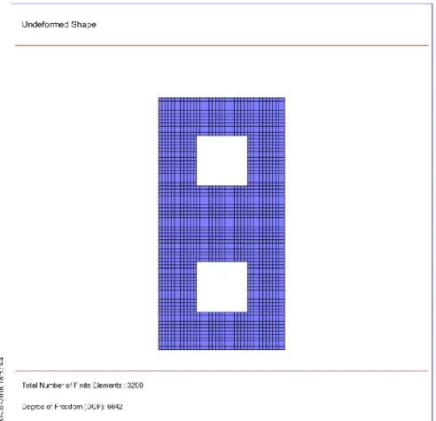
Using input data of the previous steps, a finite element analysis is performed and stresses (normal-shear)—displacements at the joints of the mesh—are calculated. Due to the actual behavior of plain masonry and the high degree of uncertainty in the previous steps, elastic analysis is a first valuable tool for such structures, especially before any repair and/or strengthening.
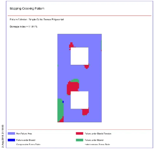
3.6. Step 6: Failure Criterion and Assessment
A failure criterion must be established for the definition of the damaged regions of the structure (as a first insight). Taking into account the conclusions of Step 2 concerning materials’ characteristics, such a criterion is proposed, and is used as an input to carry out the analysis.
These failure results are used as input data for the development of a damage index. Based on this index, the possibility of a structure to be damaged beyond a specified level (heavy, moderate, and insignificant) for various levels of ground acceleration is determined. This information is important during the analysis and redesign process for a historical structure since it gives the opportunity to investigate different scenarios with different options regarding repair/strengthening.
3.7. Step 7: Repairing and/or Strengthening Decisions and Reanalysis
According to the results of Steps 5 and 6, all the damaged regions are repaired and/or strengthened. The method to be used, the extent of the interventions, the type of the materials, etc., could be directly related to the results and are based on semi-empirical expressions for the final mechanical characteristics of masonry (see, e.g., [71]).
Last, a new structural analysis has to be performed including all the final materials, loading and structural data. Results of the analysis are subsequently used in the processes of Steps 5 and 6,
leading to a final approval (or rejection) of the decisions already taken for repair or strengthening of the existing structure.
3.8. Step 8: Explanatory Report
The last step, as a result of the proposed methodology, includes the detailed “Explanatory Report”, where all the collected information, the diagnosis, including the safety evaluation, and any decision to intervene should be fully detailed. This document is essential for eventual future analyses and interventions’ measures in the structure.
4. Computational and Mathematical Aspects
In this section, the most basic analytical constitutive laws and numerical models required for the successful implementation of the proposed methodology are presented in detail. In particular, the finite element model for the macro-modeling of masonry structures, the failure criteria, the damage indices, the performance levels and the mathematical background of fragility curves are presented.
4.1. Constitutive Laws of Masonry Materials
For the determination of the masonry compressive and tensile strength, several semi-empirical expressions are available in the literature. In the majority of these expressions, global effects contributing to the system resistance, such as buckling-effects or local-compression resistance are not considered. Recent studies [72,73] have shown that masonry codes underestimate the compressive strength of masonry with high coefficients of variation.
For the estimation of the masonry strengths of low-strength masonry, with a single leaf, the following formula have been proposed by Tassios and Chronopoulos [71]:
¦
= x
2
3
¦
− a + b¦
[in MPa]
(1)¦
=
2
3
¦
(2)where
¦ , ¦ are the compressive and tensile strength of masonry respectively; ¦ , ¦ are the compressive and tensile strength of mortar, respectively;
¦
is the compressive strength of the block/stone or brick material; is a reduction factor due to non-orthogonality of blocks (
0.5 for block stones &
2.5 for rubble stones);
is a mortar-to-block factor (
0
.
5
for rough stones and
0
.
1
for very smooth-surface stones); and
is a factor expressing the adverse effect of thick mortar joints, 1
13.5
k k0
(k = volume ofmortar/volume of masonry and k0 0.3).
However, for well-built and regular masonry structures, Tassios [74] proposed another expression for the estimation of the compressive strength:
¦
= ¦
+ 0.4 ¦
− ¦
1 − 0.8√
for ¦ >¦
(3)and
¦
= ¦
1 − 0.8√
for ¦
≤ ¦
(4)where
bm jm h
t
is the ratio between average bed (horizontal) joint thickness tjm, and average block height hbm.Based on a large database of compressive test results on masonry prisms from the literature and using regression analysis or soft computing techniques such as Artificial Neural Networks (ANNs) and Fuzzy Logic (FL), a plethora of mathematical models have been proposed for the estimation of masonry compressive strength. Detailed state-of-the-art reports can be found in the works of Sarhat and Sherwood [72], Thaickavil and Thomas [73], and Garzón-Roca et al. [75]. A common feature of these proposals (Table 1) is that they only consider the compressive strength of brick and mortar.
Table 1. Formulae for the estimation of masonry compressive strength.
Sl. No. Reference Formula
1 Engesser (1907) [76] fwc fbc fmc 3 2 3 1 2 Bröcker (1963) [77]
f
wc
0
.
68
f
bc1/2f
mc1/3 3 Mann(1982) [78]f
wc0
.
83
f
bc0.66f
mc0.18 4 Henry and Malek (1986) [79]f
wc0
.
317
f
bc0.531f
mc0.2085 Dayaratnam (1987) [80]
f
wc0
.
275
f
bc0.5f
mc0.56 Rozza (1995) [81]
f
wc
v
uf
bc
0
.
8
v
mf
mc
/
10
7 Bennett, Boyd and Flanagan (1997) [82]
f
wc
0
.
3
f
bc8 AS 3700 (2001) [83]
f
wc
h
mf
bc0.59 Dymiotis and Gutlederer (2002) [84] fwc0.3266fbc
1 0.0027 fbc0.0147fmc
10 Eurocode 6 (2005) [85]
f
wc
f
bc0.7f
mc0.3 11 Kaushik, Rai and Jain (2007) [86]f
wc0
.
317
f
bc0.866f
mc0.134 12 Gumaste, Rao, Reddy and Jagadish (2007) [87]f
wc0
.
63
f
bc0.49f
mc0.3213 Christy, Tensing and Shanthi (2013) [88]
f
wc0
.
35
f
bc0.65f
mc0.25 14 Garzón-Roca, Marco and Adam (2013) [89]f
wc
0
.
53
f
bc
0
.
93
f
mc
10
.
32
15 Sarhat and Sherwood (2014) [72]
f
wc0
.
886
f
bc0.75f
mc0.1816 Lumantarna, Biggs and Ingham (2014) [90]
f
wc0
.
75
f
bc0.75f
mc0.31 17 Kumavat (2016) [91]f
wc0
.
69
f
bc0.6f
mc0.35wc
f
, masonry compressive strength;f
bc, brick compressive strength;f
mc, mortar compressive strength;v
u, relative volume of unit;v
m, relative volume of mortar; K is a constant in Eurocode 6 formula, modified according to the National Annex for different countries. The value of this constants in the UK is 0.52 [92] while in Greece is 0.20–1.00 depending on brick/block unit properties and their arrangement;
h is a factor in Australian AS 3700 code [83] that accounts for the ratio of unit height to mortar joint thickness (1.3 for blocks of 190 mm high blocks and mortar joints with 10 mm thickness);
m is also a factor in Australian AS 3700 [83] code that accounts for bedding type (1.4 for full bedding and 1.6 for face-shell bedding).Recently, Thaickavil and Thomas [73] proposed a formula taking into account the majority of parameters affecting the masonry compressive strength. Namely, the authors, based on regression analysis on many test data (232 datasets) corresponding to the masonry unit strength of 3.1–127.0 MPa, mortar strength of 0.3–52.6 MPa and h/t ratio of 1.15–5.75, have proposed the following formula:
0.28 6 . 0 3 . 3 004 . 0 06 . 154
.
0
t h mH b mc bc wcVR
VF
f
f
f
(5)where
VF
b is the volume fraction of brick andVR
Mh the volume ratio of bed joint to mortar defined by the following equations:p u b
V
V
VF
(6)where
V
u is the volume of masonry units and Vp is the volume of prism.mV mH mH mH V V V VR (7)
where
V
mH is the volume fraction of mortar in horizontal joints andV
mV is the volume fraction of mortar in vertical joints. The volume fraction is obtained by dividing the respective volume with the corresponding total volume in the prism. The above proposed analytical formula (Equation (5)) seems to be the most reliable for the determination of masonry compressive strength [93] among a plethora of proposed equations available in the literature [76–91].4.2. Structural Modeling Techniques for Masonry Structures
As pointed out above, masonry is in fact a heterogeneous material comprising masonry units and mortar. Due to the existence of mortar joints as planes of weakness, a masonry wall exhibits distinct directional mechanical properties. Therefore, a masonry wall can be treated as an orthotropic material. Depending on the orientation of the joints to the stress directions and the applied normal stress level, four different failure modes are feasible for unreinforced masonry walls according to FEMA 356, 2000 [94]. Namely, pier diagonal tension, toe crushing, bed joint-sliding, and rocking failure can occur. The first two failure modes are considered force-controlled (brittle failure) and hence no plastic deformation capacity is considered. The last two failure modes are considered deformation-controlled (ductile failure) and a plastic deformation capacity is taken into account.
To model the structural behavior of a masonry wall, there are some influencing factors such as material properties of masonry units and mortar, dimension of the units, mortar thickness and the brittle behavior of masonry units, which should be taken into account properly. If these factors are incorporated suitably into a structural model of a masonry wall, the four above-mentioned failure modes can be simulated.
Depending on the required level of accuracy and simplicity, there are different structural modeling strategies for masonry wall elements as follows.
4.2.1. Modeling Masonry as a Three-Phase Material (Detailed Micro-Modeling Approach)
In this approach, the masonry constituents (units, mortar and unit-mortar interfaces) are modeled as they are in masonry wall elements. In other words, units and mortar in the joints are represented by continuum elements, whereas the unit–mortar interface is represented by discontinuous elements accounting for potential slip planes as shown in Figure 3b. Even though the accuracy of this approach is high, it needs high computational costs and time. In addition, the elastic and inelastic material properties of both masonry units and mortar and the unit/mortar interface mechanical property as well, are required to be determined by some realistic masonry sample tests. Therefore, this approach is mostly preferred for the analysis of small-scale experimental specimens and structural details to determine accurately their components’ stress distribution (Lourenço and Pina-Henriques, 2006 [95]; Papa, 2001 [96]; Rots, 1991 [97]; Tzamtzis and Asteris, 2003 [98]; Zucchini and Lourenço, 2006 [99]).
Figure 3. Modeling strategies for masonry: (a) typical masonry specimen; (b) detailed
micro-modeling; (c) simplified micro-modeling; and (d) macro-modeling (Lourenço, 1996 [100]).
Recently, Sarhosis and Lemos (2018) [101] proposed a detailed micro-modeling approach for the analysis of masonry couplets and prisms. In this approach, masonry constituents are represented as an assemblage of densely packed discrete irregular deformable particles bonded together by zero thickness interface elements. The advantage of this approach is that failure can occur at the masonry units, mortar and/or brick–mortar interface in a realistic manner. In this approach, the crack initiation and propagation can be traced as well.
4.2.2. Modeling Masonry as a Two-Phase Material (Simplified Micro-Modeling Approach)
In this approach, masonry units/blocks are represented by fictitious expanded units in size (Phase I) to keep the geometry consistent, however, mortar is not modeled explicitly. The fictitious expanded unit dimensions are of the same size as the original dimensions plus the real joint thickness, as shown in Figure 3c. The interface’s stiffness is represented numerically by the stiffness of the real joint. The elastic or inelastic, isotropic model is used for the behavior of the masonry units to simulate properly their possible crushing and cracking propagation patterns. The interaction between the expanded units is represented by an interface element (Phase II). To simulate the behavior of mortar joints, the properties of the mortar and the interface elements are lumped into the zero-thickness common interface elements. This approach leads to the reduction in computational intensiveness and yields a model that is applicable to a wider range of structures. In fact, the drawback of the large computational effort required by the detailed micro-modeling is partially overcome by the simplified micro-modeling strategy. Cracking in the masonry units can also be simulated by assigning potential vertical zero thickness interfaces (unit to unit) at the unit’s center lines (Lourenço 1996 [100]). Another important factor influencing the accuracy of the simplified micro-modeling strategy is the masonry units’ aspect ratio that should be taken into account. According to Schlegel and Rautenstrauch (2004) [102], aspect ratio of stone masonry units (stone shape or the ratio of stone unit length to height lst/hst) has an effect on the joint failure and load-carrying capacity of masonry walls. For example, as shown in Figure 4, the load-carrying capacity of a masonry wall increases as a result of the decreasing stone rotation with an increasing ratio of lst/hst. Furthermore, it can be observed in this figure that an increase in the stone unit dimensions in each direction (expanding stone units), would increase the ultimate load to some extent depending on the ratio of lst/hst. Therefore, it can be concluded that expanding masonry units in the simplified micro-modeling strategy may alter the accuracy of the analysis depending on the
mortar joint relative thickness. Finally, it should be kept in mind that, although this procedure is preferred to the abovementioned detailed micro-modeling approach, it is still time consuming as the masonry structure size increases [103]. This modeling strategy has been used successfully in the literature to investigate nonlinear static and dynamic behavior of masonry wall elements [104–109], masonry buildings [110,111], ancient structures [112–117], stone masonry arches and aqueducts [117–123] and masonry infilled frames [124].
Recently, Mohebkhah et al. (2018) [124] used this strategy to investigate the nonlinear dynamic behavior of an ancient dry-joint stone masonry tower subjected to earthquake excitations. The numerical model developed using the distinct element method software 3DEC [125], in which the stone blocks are assumed to behave as rigid elements connected by zero-thickness interfaces. The zero thickness interfaces between adjacent blocks were modeled using the Mohr–Coulomb slip model. Since the tower has been constructed with dry joints, both the cohesion and tensile strength at the interfaces are assumed to be zero. During the dynamic analysis, no viscous damping is assumed, the only dissipation being due to frictional sliding on the joints. This conservative assumption is often used in simulating stone masonry structures containing dry joints (Papantopoulos et al., 2002, [126]). This study shows that the tower sustains considerably large lateral drifts in each direction without collapse. This large lateral drift may be attributed to the governing failure mode of the tower, which is a sliding shear failure mode throughout the tower height.
Figure 4. Ultimate loads for different variations of stone height (hst) and of stone unit length (lst)
(Schlegel and Rautenstrauch, 2004 [102]).
4.2.3. Modeling Masonry as a One-Phase Material (Macro-Modeling Approach)
In this approach, there is no distinction between the masonry constituents (i.e., units and mortar) and in fact they are smeared out in a homogeneous, isotropic or anisotropic continuum (Figure 3d). For the cases in which blocky behavior is the dominant deformation mode such as small masonry walls or masonry structures with large masonry units, considering a masonry wall as a homogeneous media may lead to the difficulty of simulating the failure modes. However, this approach is preferred for the analysis of large-scale real masonry structures, because of the reduced time and memory requirements. On the basis of this approach, some computational models based on continuum plasticity (Lourenço, 1996 [100] and Lourenço et al., 1998 [127]) and continuum damage (Papa et al., 2000 [128]) have been developed and implemented successfully for in-plane
analysis of masonry shear walls. Lourenço et al. (1998 [127]) developed a homogeneous anisotropic continuum model for the analysis of masonry as a composite. In this model, the behavior of the composite media is stated, based on average stresses and strains, assuming different elastic and inelastic properties along the material axes.
Syrmakezis and Asteris [129]) proposed a general anisotropic (orthotropic) failure criterion for masonry under biaxial stress state, using a cubic tensor polynomial. This failure criterion was then used by Asteris and Tzamtzis [130] for the non-linear macro-modeling and analysis of unreinforced masonry shear walls under biaxial stress state using the finite element method. The proposed failure criterion takes into account all possible combinations of plane stress state and makes it easier to be included into existing software for the analysis of masonry walls. The detailed description of this methodology is given in Sections 3.3 and 3.4. Asteris [131] also investigated the influence of the masonry infill panel opening in the reduction of the infilled frames stiffness by means of this technique.
El-Dakhakhni et al. [132] developed a macro-model for in-plane analysis of concrete masonry walls with and without reinforcements. In this multi-laminate model, a masonry wall is simulated by an equivalent homogeneous media consisting two sets of planes of weakness along the head and bed joints. To determine the global behavior of the model, the influence of these planes of weakness is smeared. This modeling technique allows prediction of the different possible failure modes, whether the planes of failure follow the mortar joints or not (El-Dakhakhni et al., 2006, [132]). The advantage of this model is that it can predict the initiation and progress of different failure modes (i.e., head joint, bed joint or homogeneous media failure) in a separate or a combined manner. 4.2.4. Modeling Masonry Using Equivalent Frame Method
The most widely used method for the modeling of real cases masonry structures is the simplified analysis method (SAM). The SAM is based on the macro-element approach that has been first proposed and developed by Magenes and Della Fonata (1998) [133] to overcome the shortcomings of the previously proposed method of “story-mechanism” by Tomazevic and Weiss (1990) [134]. The SAM stems from the concept of framed buildings analysis using beam and beam– columns elements. In fact, in the SAM to simulate the in-plane behavior of a masonry wall panel, the constituent piers and spandrel beams are substituted by the equivalent beam–columns elements with appropriate mechanical properties. Therefore, sometimes the SAM is called the equivalent frame method (EFM) which is a familiar method and has been widely used to analyze RC coupled shear walls in the literature (Figure 5).
Figure 5. A schematic representation of equivalent frame model for planar walls with openings
The SAM has been used successfully by Magenes and Della Fontana (1998) [133] to analyze two multi-story masonry walls subjected to lateral loads. The SAM was then developed by Magenes (2000) [135] to be used for seismic assessment of practical and historic masonry buildings making use of displacement spectra and of the substitute-structure approach. Kappos et al. (2002) [136] investigated the effectiveness of the SAM or EFM for the design and/or assessment of masonry buildings. Penelis (2006) [137] based on the concept of the EFM proposed an approach for the pushover analysis of URM buildings. This approach is similar to the SAM of Magenes and Della Fontana (1998) [133], however, it uses an analytical approach and a Mohr–Coulomb failure criteria for flexural and shear strengths, respectively. Furthermore, the shear stiffness and ultimate shear deformation capacity of wall elements are estimated from experimental tests results (Penelis, 2006, [137]). Pasticier et al. (2008) [138] investigated the capability of a commercial software for pushover analysis of masonry buildings using the EFM. This study showed that the EFM can be used only for pushover analysis of masonry walls of usual and regular geometry (Pasticier et al., 2008, [138]). This is because the software does not take into account the effects of axial load variation in the piers’ shear strength capacity during the analysis process.
The main advantage of the SAM is that it is based on simple strength criteria of masonry piers and spandrel beams corresponding to the well-known flexural and shear failure modes (Magenes and Della Fontana, [133]). In addition, it requires low computational effort to simulate both linear and nonlinear lateral load behavior of practical large masonry wall panels. Detailed state-of-the-art reports can be found in [139–154].
In light of the above and despite the plethora of mathematical models that have been proposed for the modeling of masonry structures, for real masonry structures, it is preferable to use simplified macro-models such as modeling the masonry as a one-phase material (macro-modeling approach) while the use of more sophisticated micro-models is suggested for the modeling of special parts of the masonry structural model. Detailed works on the advantages and disadvantages among different mathematical models about masonry structures can be found in [40,100,101,155,156].
4.3. Anisotropic Finite Element Macro-Model
The basic concepts of the finite element method are well documented and are not repeated in this paper. Only the essential features are presented. In this paper, an anisotropic (orthotropic) finite element model is proposed for the macro-modeling of masonry structures. Specifically, a four-node isoparametric rectangular finite element model with eight degrees of freedom (DOF) is used (Figure 6).
x,u
y,v
2
1
3
4
a
b
a
b
Figure 6. Finite element macro-model dimensions.
The major assumption when modeling masonry behavior under plane stress is that the material is homogeneous and anisotropic. Specifically, the material shows a different modulus of elasticity in
the x direction (Ex) (direction parallel to the bed joints of brick masonry) and the y direction (Ey)
(perpendicular to the bed joints). In the case of plane stress, the elasticity matrix is defined by
xy
G
0
0
0
yx
xy
1
y
E
yx
xy
1
xy
y
E
0
yx
xy
1
yx
x
E
yx
xy
1
x
E
D
(8)where νxy and νyx are the Poisson’s ratios in the xy and yx plane, respectively, and Gxy is the shear
modulus in the xy plane. It is worth noticing that, in the case of plane stress in an anisotropic material, the following equation holds
xy
y
E
yx
x
E
(9) 4.3.1. Displacement FunctionsFigure 6 shows the four node isoparametric rectangular finite element model, with nodes 1, 2, 3, 4 numbered in an anticlockwise order. The displacements of a node have two components, namely
i i iu
v
(10)and the eight components of element displacements are listed as a vector
e
1 2 3 4 (11)The displacements within an element have to be uniquely defined by these eight values. The simplest representation is given by two linear polynomials, namely
u x y
x
xy
y
v x y
x
xy
y
,
,
a
a
a
a
a
a
a
a
1 2 3 4 5 6 7 8 (12)The eight constants
i
(where i = 1, 2, …, 8) can be evaluated easily by solving the two sets of four simultaneous equations, which will arise if the nodal coordinates are inserted and the displacements equated to the appropriate nodal displacements.4.3.2. Strain (Total)
The total strain at any point within the element can be defined by its three components which contribute to the internal work. Thus,
x
y
,
x
v
y
y
,
x
u
y
y
,
x
v
x
y
,
x
u
xy
yy
xx
(13)With displacements known at all points within the element, the strains at any point can be determined. These will always result in a relationship that can be defined in matrix notation according to:
B
e (14)where B is a suitable linear operator. 4.3.3. The Stiffness Matrix
The stiffness matrix of the finite element is defined by the general equation
eV
)
vol
(
d
DB
T
B
e
K
(15)The analytical form of the anisotropic finite element stiffness matrix is defined by integration over the area of the element (see Appendix A). Extensive research works on the modeling of anisotropic brick masonry behavior using finite elements can be found in Samarasinghe’s PhD thesis [157], Asteris’s PhD thesis [158] and a work by Asteris [159] focused on the problem of the analysis of anisotropic non-linear masonry.
4.4. Failure Criteria
The key point for a reliable seismic vulnerability assessment of masonry is the failure criterion used for the determination of masonry failure. In this section, failure criteria both for isotropic and anisotropic behavior of masonry materials are presented. Namely, two semi-empirical isotropic failure criteria, the cubic tensor polynomial failure criterion, and a failure criterion based on Artificial Neural Networks (ANNs) are presented in the following three sub-sections.
4.4.1. Semi-Empirical Isotropic Failure Criteria
Despite the distinct anisotropic nature of masonry material, many researchers use for the modeling of its failure isotropic failure criteria such as the failure criterion proposed by Kupfer and Gerstle [160] for concrete material and the Von Mises modified failure criterion proposed by Syrmakezis et al. [8,25] for modeling masonry under biaxial stress state.
The first isotropic criterion was proposed by Kupfer et al. [160,161] and has been adopted by many researchers [162–164] assuming isotropic behavior for masonry material. Based on this criterion, the failure (Figure 7) can be approximated for the three-stress state under the axis of symmetry
1
2
by the following expressions in terms of principal stress:For the case under biaxial compression by
0
ƒ
65
.
3
ƒ
ƒ
ƒ
wc 1 wc 2 2 wc 2 wc 1
(16)
wc 2 wc wt wc 1ƒ
8
.
0
1
ƒ
ƒ
ƒ
(17)and for the case under biaxial tension by
wc wt wc 1
ƒ
ƒ
ƒ
(18)It should be noted that a very small area of the heterosemous biaxial stress state is expressed by Equation (16), as can be noticed in Figure 7.
The second isotropic criterion (Figure 8) is the Von Mises modified isotropic failure criterion proposed by Syrmakezis et al. [8,25] for the modeling of masonry under biaxial stress state and has been adopted by many researchers [165–170] assuming isotropic behavior for masonry material.
Based on this criterion, the failure can be approximated for the three-stress state under the axis of symmetry
1
2
by the following expressions also in terms of principal stress:For the case under biaxial compression by
0
1
ƒ
ƒ
ƒ
ƒ
wc 2 wc 1 2 wc 2 2 wc 1
(19)for the case of heterosemous biaxial stress state (tension/compression) by
wc 2 wc wt wc 1ƒ
1
ƒ
ƒ
ƒ
(20)and for the case under biaxial tension by
wc wt wc 2 wc 1
ƒ
ƒ
ƒ
ƒ
(21)4.4.2. Cubic Tensor Polynomial
A key point for a successful application of the proposed methodology is the use of a reliable failure criterion for the modeling of the masonry failure. To this end, a tensor polynomial has been used for the modeling of the masonry failure. Specifically, according to this criterion, the masonry material is assumed to exhibit a distinct anisotropic nature and the failure surface can be described by the following equation:
¦
failure
exceeded
1
failure
1
failure
no
1
k
σ
j
σ
i
σ
ijk
F
j
σ
i
σ
ij
F
i
σ
i
F
σ
(22)where i, j, k = 1, 2,..., 6. Fi, Fij and Fijk are (strength) tensors of the second, fourth and sixth rank,
respectively.
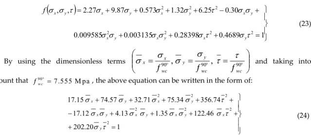
Based on the above equation, restricting the analysis to a plane stress state and assuming that a cubic formulation is a reasonably accurate representation of the failure surface and by taking into consideration the symmetry and anisotropic nature of the material [129,171,172], the masonry failure surface, known as the cubic tensor failure criterion, can be expressed by Equation (23).
wc 1 ƒ wc 2 ƒ 0 ƒ 65 . 3 ƒ ƒ ƒ wc 1 wc 2 2 wc 2 wc 1 wc 2 wc wt wc 1 ƒ 8 . 0 1 ƒ ƒ ƒ wc wt wc 1 ƒ ƒ ƒ
Figure 7. Kupfer and Gerstle isotropic failure criterion.
Axi s of sym met ry wc 1 ƒ wc 2 ƒ 0 1 ƒ ƒ ƒ ƒ wc 2 wc 1 2 wc 2 2 wc 1 wc wt wc 2 wc 1 ƒ ƒ ƒ ƒ wc 2 wc wt wc 1 ƒ 1 ƒ ƒ ƒ
1 4689 . 0 28398 . 0 003135 . 0 009585 . 0 30 . 0 25 . 6 32 . 1 573 . 0 87 . 9 27 . 2 , , 2 2 2 2 2 2 2
y x y x y x y x y x y x y x f (23)By using the dimensionless terms
¦
¦
¦
90,
90,
90 wc wc y y wc x x
and taking intoaccount that 90 7.555 M pa
w c
¦ , the above equation can be written in the form of:
1 20 . 202 46 . 122 35 . 1 13 . 4 12 . 17 74 . 356 34 . 75 71 . 32 57 . 74 15 . 17 2 2 2 2 2 2 2 y x y x y x y x y x y x (24)
Eliminating all third-order terms in Equation (24), a simplified failure criterion is derived [129,171,172]: 1 91 . 25 74 . 356 34 . 75 71 . 32 57 . 74 15 . 17 2 2 2 y x y x y x (25)
This simple form of the criterion has already been used [173–176]. In Figures 9 and 10, graphical representations of cubic and simplified failure criterion in dimensionless principal and normal stress terms are depicted. Detailed description about the cubic tensor polynomial masonry failure criterion can be found in the works of Syrmakezis and Asteris [129] and Asteris [171,172].
(a) (b)
Figure 9. Dimensionless failure surface of masonry material using the cubic tensor polynomial
failure criterion: (a) non-dimensionless normal stress terms; and (b) non-dimensionless principal stress terms.
(a) (b)
Figure 10. Dimensionless failure surface of masonry material using the simplified failure criterion:
(a) non-dimensionless normal stress terms; and (b) non-dimensionless Principal stress terms. 4.4.3. Failure Criterion Based on Artificial Neural Networks
This section summarizes the basic concepts of artificial neural networks (ANNs) as well as the architecture of the optimum ANN model developed for the modeling of masonry compressive strength. ANNs are information processing models configured for a specific application through a training process. A trained ANN has learned to rapidly map a given input into the desired output quantities (similar to curve fitting procedures) and thereby can be used as a meta-model enhancing the computational efficiency of a numerical analysis process. This major advantage of a trained ANN over conventional numerical analysis procedures, such as regression analysis, under the condition that the training and validation data cover the entire range of input parameters values, is that the results can be produced with much less computational effort [93,177–186].
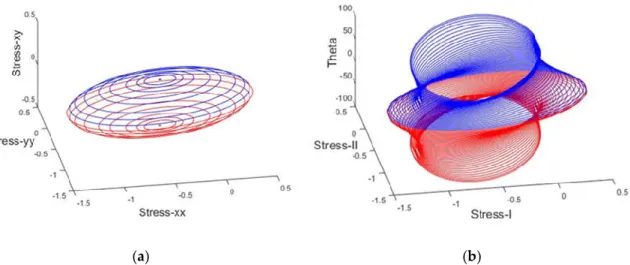
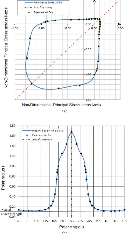
In the present study, using the available in the literature experimental results conducted by Kupfer and Gerstle (1973) [160] concerning the failure of concrete under biaxial stresses, the Back-Propagation Neural Network (BPNN) technique was used for the development of a reliable and robust ANN that can predict the failure of concrete. To this end, for each failure point (experimental data), the polar angle was used as input parameter, while the polar radius was selected as output parameter.
In light of the above, 36,900 BPNN models (900 with one hidden layer and 36,000 with two hidden layers) were studied. The parameters used for the training of NN models are summarized in Table 2. All developed ANN models were ranked based on the Root Mean Square Error (RMSE). Based on the results, the optimum BPNN model is that of 1-3-5-1 structure. This network corresponds to the case of architecture with two hidden layers of 3 and 5 neurons, respectively (Figure 11). Using this optimum ANN model, the concrete failure criterion under biaxial stress state both in dimensional principal stresses terms (Figure 12a) and in polar coordinates (Figure 12b) was produced.
Table 2. Training Parameters of BPNN models.
Parameter Value
Training Algorithm Levenberg–Marquardt Algorithm Number of Hidden
Layers 1; 2
Number of Neurons
per Hidden Layer 1 to 30 by step 1
Cost Function Mean Square Error (MSE); Sum Square Error (SSE)
Transfer Functions Hyperbolic Tangent Sigmoid transfer function (tansig); Log-sigmoid transfer function (logsig); Linear transfer function (purelin)
(a)
(b)
Figure 12. Concrete failure criterion under biaxial stress state: (a) in dimensional principal stresses
It is common practice in published literature on NN models for the authors to present the architecture of the optimum NN model without providing any information regarding the final values of NN weights. Admittedly, this practice has very little value for other researchers and practicing engineers. To be useful, a proposed NN architecture should be accompanied by the (quantitative) values of weights [186]. In such a case, the NN model can be readily implemented in an MS-Excel spread sheet, thus available to anyone interested in the issue of modeling.
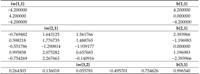
In this study, the final values of weights and biases of the optimum proposed BPNN 1-3-5-1 model are explicitly reported in Figure 13 and Table 3. By using the reported values of weights and biases, as well as the architecture of the NN (Figure 11), one can easily build an ANN-based estimator for the failure criterion of concrete under biaxial stress state.
Figure 13. Final weights and bias values of the optimum BPNN model 1-3-5-1 (the values are
presented in Table 3).
Table 3. Final weights and bias values of the optimum BPNN model 1-3-5-1.
iw{1,1} b{1,1} −4.200000 4.200000 4.200000 0.000000 −4.200000 −4.200000 iw{2,1} b{2,1} −0.769482 1.643125 1.561766 2.393966 0.598218 1.776735 1.488765 −1.196983 −0.551786 −1.290814 −1.939177 0.000000 0.995858 2.075282 0.657683 1.196983 −0.754269 2.267663 −0.140916 −2.393966 iw{3,2} b{3,1} 0.264303 0.136018 0.055781 −0.495701 0.754626 0.996540 iw{1,1}, weights values for input layer; iw{2,1}, weights values for first hidden layer; iw{3,2}, weights values for second hidden layer; b{1,1}, bias values for first hidden layer; b{2,1}, bias values for second hidden layer; b{3,1}, bias values for output layer.
![Figure 3. Modeling strategies for masonry: (a) typical masonry specimen; (b) detailed micro-modeling; (c) simplified micro-modeling; and (d) macro-modeling (Lourenço, 1996 [100])](https://thumb-eu.123doks.com/thumbv2/123dok_br/18635185.911377/12.892.152.749.117.473/modeling-strategies-specimen-detailed-modeling-simplified-modeling-lourenço.webp)
![Figure 4. Ultimate loads for different variations of stone height (hst) and of stone unit length (lst) (Schlegel and Rautenstrauch, 2004 [102])](https://thumb-eu.123doks.com/thumbv2/123dok_br/18635185.911377/13.892.232.654.525.887/figure-ultimate-different-variations-height-length-schlegel-rautenstrauch.webp)
![Figure 5. A schematic representation of equivalent frame model for planar walls with openings (Magenes, 2000, [134])](https://thumb-eu.123doks.com/thumbv2/123dok_br/18635185.911377/14.892.252.622.812.1116/figure-schematic-representation-equivalent-frame-planar-openings-magenes.webp)