Nuno Filipe Ferreira Lopes
Licenciado em Ciências de Engenharia
Development and implementation of
strategies for the incorporation
of reinforcing elements in aluminium alloys
by solid state processing
Dissertação para obtenção do Grau de Mestre em Engenharia Mecânica
Orientador: Professora Doutora Rosa Maria Mendes
Miranda
Co-orientador: Professor Doutor Telmo Jorge Gomes dos
Santos
Março de 2012
Copyright
Development and implementation of strategies for the incorporation of reinforcing elements in
aluminium alloys by solid state processing
©Nuno Filipe Ferreira Lopes, FCT-UNL, 2012
A Faculdade de Ciências e Tecnologia e a Universidade Nova de Lisboa têm o direito, perpétuo
e sem limites geográficos, de arquivar e publicar esta dissertação através de exemplares
impressos reproduzidos em papel ou de forma digital, ou por qualquer outro meio conhecido ou
que venha a ser inventado, e de a divulgar através de repositórios científicos e de admitir a sua
cópia e distribuição com objectivos educacionais ou de investigação, não comerciais, desde que
i
Agradecimentos
A realização deste trabalho apenas foi possível graças ao contributo, empenho e apoio de
várias pessoas às quais é imprescindível agradecer.
Em primeiro um especial agradecimento à minha Orientadora, Professora Rosa Maria
Mendes Miranda pela oportunidade de realizar este desafiante trabalho, assim como, pela
disponibilidade, empenho e interesse no desenvolvimento deste trabalho
Um sincero obrigado ao meu Co-Orientador, Professor Telmo Santos, pelo seu apoio,
orientação e tempo disponibilizado na realização prática deste trabalho, assim como pela
amizade demonstrada.
Um sincero obrigado a todos os Professores do Núcleo de Tecnologia Industrial, pelo
interesse demonstrado e pelas ajudas preciosas na realização deste trabalho.
Um especial agradecimento aos Srs. António Campos e Paulo Magalhães por toda a sua
assistência técnica neste trabalho, assim como pelo apoio e grande amizade sempre
demonstrada. Não podia deixar de agradecer também ao Mestre João Gonzalez, por toda a ajuda
prestada.
Uma especial abraço ao meu colega João Russo pela amizade demonstrada durante a
realização deste trabalho, assim como os necessários momentos de distracção.
Aos meus colegas e amigos, também futuros engenheiros, um muito obrigado pela ajuda
e força demonstrada no decorrer desta vida académica. Um especial abraço para os meus
amigos Filipe Marques, Jorge Bernardo, Hélder Guerra, Rodrigo Pires, Gonçalo Sorger, Duarte
Lousa, João Violante, Luís Almeida e Tiago Baptista.
A toda à minha família em especial, aos meus País e Irmão um muito obrigado por todo o
apoio e carinho demonstrado durante todos estes anos.
Aos meus grandes amigos de sempre um profundo obrigado por todos os momentos de
distracção e apoio durante estes anos de faculdade, e principalmente durante a realização deste
iii
Resumo
Este trabalho visou estudar diferentes estratégias de processamento de superfícies por
fricção linear para a produção de compósitos de matriz metálica A primeira consistiu numa pré
deposição de partículas sobre o material base e posterior processamento. Na segunda
utilizaram-se pinos consumíveis preenchidos com partículas de reforço. Em cada uma destas estratégias
usou-se corrente eléctrica num processo sob patente.
Como substrato utilizou-se alumínio AA5083-H111 e como reforço, partículas de
carboneto de silício e alumina com tamanhos médios de 35 e 45 µm.
A pré deposição de partículas de reforço revelou-se mais eficaz que o uso de ferramentas
consumíveis com partículas. Estes últimos produziram revestimentos com uma distribuição não
homogénea de partículas e baixa interligação entre o substrato e o reforço.
Pré depositando partículas de alumina, observou-se maior extensão e profundidade com
um aumento de dureza no reforço de 60 %, enquanto que com partículas de carboneto silício o
aumento de dureza foi de 300 %, embora com extensões e profundidades da camada reforçada
menores que os observados para a alumina nas mesmas condições processuais e menor
homogeneidade dos revestimentos.
Com a passagem de corrente eléctrica verificou-se um aumento de extensão e
profundidade (500 e 40 % respectivamente), mas um decréscimo de dureza (10 %), com a
v
Abstract
This investigation aimed to study new surface processing strategies to produce reinforced
surface metal matrix composites by Friction Stir Processing. The first consisted on pre-placing
reinforcing particles over the surface, while the second used consumables drilled holes filled
with reinforcing particles. Each strategy was investigated using an electric current in a process
under patenting.
Aluminium AA5083-H111 plates were used as base material. Silicon carbide and alumina
particles with median sizes of 35 and 45 µm, respectively, were used.
Pre deposition of reinforcing particles proved to be more effective than the use of
consumable tools packed with particles. The last ones produced coatings with a non
homogeneous distribution and poor bonding between the substrate and the reinforcing coating.
The pre deposition of alumina produced a higher extension and depth of reinforced layer
and an increase in hardness of 60%, while silicon carbide produced an increase in hardness of
300 %, though in a smaller extension and depth than alumina under the same processing
conditions.
Using the electric current a significant raise of 500% and 40% was observed in extension
vii
Palavras Chave
Processamento por fricção linear
AA5083-H111
Carboneto silício
Alumina
Depósito por fricção linear
Compósitos superficiais de matriz metálica
Keywords
Friction stir processing
AA5083-H111
Silicon carbide
Alumina
Friction stir deposition
ix
Índice
Agradecimentos ... i
Resumo ... iii
Abstract ... v
Palavras Chave ... vii
Keywords ... vii
Table index ... xi
Figure index ... xiii
Abbreviations and Symbols ... xvii
1 Introduction ... 1
1.1 Objectives ... 2
1.2 Structure ... 2
2 State of art ... 3
2.1 Base Materials ... 3
2.1.1 Aluminum alloys ... 3
2.1.2 Magnesium alloys ... 5
2.1.3 Copper alloys... 5
2.2 Solid Processing ... 5
2.2.1 Process parameters ... 7
2.2.2 Multiple-Pass FSP ... 11
2.3 Methods of reinforcement ... 13
2.4 Reinforcement materials ... 16
2.4.1 Ceramic reinforcing ... 17
2.4.2 Metallic reinforcements ... 24
2.4.3 Nanotubes ... 26
2.4.4 Copper ... 26
2.5 Conclusion ... 27
3 Experimental set-up... 29
3.1 Materials characterization ... 29
3.2 Equipment ... 30
3.3 Clamping base system ... 31
3.4 Electric system ... 31
3.5 Testing description ... 35
x
3.5.2 Friction Stir Processing (FSP) with consumable tool with drilled holes packed
with particles-P2. ... 37
3.6 Characterization techniques ... 40
3.6.1 Polishing procedure ... 40
3.6.2 Metallography ... 41
3.6.3 SEM/EDS ... 42
3.6.4 Hardness testing ... 42
3.7 Conclusions ... 44
4 Results and discussion ... 45
4.1 Friction stir process with predeposition of reinforcing particles. (P1) ... 45
4.1.1 Evaluation of parameters in friction surfacing (P1_P). ... 45
4.1.2 Friction stir process reinforced with alumina particles (P1_A). ... 46
4.1.3 Friction stir process reinforced with silicon carbide particles (P1_S). ... 57
4.2 Friction stir process with consumable driller tool packed with particles (P2). ... 64
4.2.1 Evaluation of parameters in process (P2_P) ... 64
4.2.2 Friction stir process with consumable driller tool packed with alumina particles (P2_A). 69 4.2.3 Friction stir process with consumable driller tool packed with silicon carbide particles (P2_S) ... 74
4.3 Friction stir process with predeposition of reinforcing particles using electric current (P1_E). ... 84
4.3.1 Friction stir process with predeposition of reinforcement with alumina (P1_E_A). ... 84
4.3.2 Friction stir process with predeposition of reinforcing silicon carbide particles using electric variant (P1_E_S). ... 94
4.4 Friction stir process with consumable driller tool with electric variant (P2_E). ... 94
5 Final conclusions and suggestions for future work ... 97
References ... 99
Annexes ... xix
A1 – Technical drawing of FSP tool body. ... xx
A2 – Technical drawing of FSP tool shoulder profiles. ... xxi
xi
Table index
Table 2.1 – Series of aluminium alloys and main alloying elements [1]. ... 4
Table 2.2 – Treatments specifications [1]. ... 4
Table 2.3 - Key benefits of friction stir welding and friction stir processing [28]. ... 7
Table 2.4 - Process parameters [44]. ... 16
Table 2.5 - Summary of the mean Al2O3 cluster size, Al matrix grain size and micro hardness value of the SCLs produced using various number of FSP passes [23]. ... 21
Table 2.6 - Tensile properties of the composite (standard deviations are shown in parenthesis) [24]. ... 25
Table 3.1 - AA5083 H111 chemical composition. ... 29
Table 3.2 - AA5083 H111 physical properties... 29
Table 3.3 - AA5083-H111 mechanical properties ... 30
Table 3.4 - AL AW 2007-H4 aluminium alloy physical properties ... 30
Table 3.5 - AL AW 2007-H4 alloy mechanical properties ... 30
Table 3.6 - Trial group process one description. Conventional FSP with and without electric variant. ... 37
Table 3.7 - Consumable pins developed and respective designation. ... 39
Table 3.8 - Process 2 description ... 40
Table 4.1 - Parameters of P1. ... 45
Table 4.2 – SEM analyses from process one, reinforced with alumina particle ... 54
Table 4.3 - Parameters of process one with silicon carbide. ... 57
Table 4.4 - Parameters of process two. ... 64
Table 4.5 – Macrographs from test group P2_P, and values for extension and height. ... 68
Table 4.6 - Parameters of process two with alumina powders. ... 69
Table 4.7 - Parameters of process two with silicon carbide particles. ... 74
xiii
Figure index
Figure 2.1 - Schematic illustration of FSP [27]... 6
Figure 2.2 - FSP tool pin profiles exemples [20]. ... 8
Figure 2.3 - Effect of pin profiles on FSP zone hardness [20]. ... 9
Figure 2.4 – Macrographs of cross sections of nugget zone after first pass with different pin profiles [36]. ... 9
Figure 2.5 – Hardness profiles across FSP stirred zones after three passes with different tool profiles at a rotating speed of 1500 rev/min [36]. ... 10
Figure 2.6 - Shoulder geometries [38]. ... 10
Figure 2.7 - Tilt angle definition [27]. ... 11
Figure 2.8 - Multiple passes of FSP [39]... 12
Figure 2.9 - Optical microscopic images of samples processed by different passes in AMCZ and transition region from composite coating to aluminium alloy substrate: a) AMCZ after one pass; b) AMCZ of two passes; c) AMCZ after three passes; d) transition region after one pass, e) transition region after two passes; and f) transition region after three passes (17.64 kN axial force) [39]. ... 12
Figure 2.10 - Hardness profile of cross-section in a multi-pass FSP [40]. ... 13
Figure 2.11 - Schematic illustration of the groove FSP setup, a) groove, and b) toll aligned with groove [12]. ... 14
Figure 2.12 - FSP procedure: a) Cuter groove with inserted particles; b) Closing the groove with particles; c) FSP with pin tool; c) multiple passes of FSP [43]. ... 14
Figure 2.13 - Macrographs of bead cross section, with different placements of grooves [28]. .. 15
Figure 2.14 - Schematic representation of the drilled holes in surface reinforcing [6]. ... 16
Figure 2.15 - Variation of Brinell hardness in as-cast, FSPed A356 and composite samples [27]. ... 18
Figure 2.16 - SEM image of particle dispersion in hybrid composite produced by FSP [27]. ... 18
Figure 2.17 - Microhardness values of specimens FSPed a) without SiC particles and b) with SiC particles in different traverse speeds [12]. ... 19
Figure 2.18 - a) Wear rate of samples as a function of sliding distance for BS and SMMNC, b) Variation of friction coefficient BM and SMMNC [43]. ... 20
Figure 2.19 - Cross section micrographs of the SCL fabricated using one a), three b) or four c) FSP passes showing Al2O3 particles clustering/dispersion within the stirred zone [23]. ... 21
Figure 2.20 - Tensile properties of the composites and FSP materials produced by different passes [25]. ... 22
xiv
Figure 2.22 - a) Effect of hybrid ratio of reinforcements on the average friction coefficient at
normal applied loads of 2, 5, and 10 N, b) Effect of hybrid ratio of reinforcements on wear
volume losses at normal applied loads of 2, 5, and 10 N [57]. ... 24
Figure 2.23 - SEM images showing uniformly distributed NiTi particles in various parts of the nugget region of FSP composites a)–c) and of annealed composites d)–f) [64]. ... 25
Figure 2.24 - Methodology of repair of copper–nickel 70/30 using DMD and FSP. First the corrosion hole is machined to a regular shape. This is followed by laser deposition and FSP. The surface is finally machine to disire finish. [55]. ... 27
Figure 3.1 - Milling cotter at DEMI. Degrees of freedom representation ... 31
Figure 3.2 – Cross section of the simulated tool ... 32
Figure 3.3 – Electric densety in process two. ... 32
Figure 3.4 – Electric flow in the tool. ... 33
Figure 3.5 – Analysis montage. (A) Detail from interface between BM and consumable pin. .. 34
Figure 3.6 – Labview front panel. ... 34
Figure 3.7 – Test names for investigation. ... 35
Figure 3.8 - Methods of reinforcement. (A) With alumina particles, (B) with silicon carbide particles ... 36
Figure 3.9 - Tool profile without electric current. ... 37
Figure 3.10 – Schematic procedure for process two. ... 38
Figure 3.11 Tool section view. ... 39
Figure 3.12 – Optical microscope from DEMI. ... 41
Figure 3.13 – Leica DWI 5000 M inverted geometry microscope used for both macroscopic and microscopic analysis. ... 42
Figure 3.14 – Vickers Hardeness Testing Machine. ... 43
Figure 3.15 – Vickers hardness profiles for trial group P1. ... 43
Figure 3.16 - Vickers hardness profiles for trial group P2 ... 44
Figure 4.1 – Macrograph of tracks from test group P1_P. ... 46
Figure 4.2 – Macrograph from tracks for trial group P1_A. ... 47
Figure 4.3 - Cross section micrographs of test sample P1_A_TS1. (A) Macrographs of bead cross section in BF, (B) Macrographs of bead cross section in DF, (C,D) Details of interface zone. ... 48
Figure 4.4 - Cross section micrographs of test sample P1_A_TS2. (A) Macrographs of bead cross section in BF, (B) Macrographs of bead cross section in DF, (B,C) Details of reinforced layer in BF, (E,F) Details of reinforced layer in DF. ... 49
xv
Figure 4.6 - Cross section micrographs of test sample P1_A_TS3. (A) Macrographs of bead
cross section in BF illumination, (B) Sliding of reinforced layer in BF, (C) Macrographs of bead
cross section in DF illumination, (D,E) Details of interface zone in DF, (F) Sliding of reinforced
layer in DF, (G) Burr with alumina particles ... 51
Figure 4.7 – EDS image and points of analyses. ... 53
Figure 4.8 - – Hardness profiles from test samples: (A) P1_A_TS1, (B) P1_A_TS2, (C) P1_A_TS3 ... 56
Figure 4.9 - Hardness profile along cross section for P1_A_TS1 to TS3. ... 57
Figure 4.10 - Macroscopic observation from tracks for trial group P1_S. ... 58
Figure 4.11 - Cross section micrographs of test sample P1_S_TS1. (A) Macrographs of bead cross section, (B,D) Details of interface zone in RS, (C) Details of interface zone in AS. ... 59
Figure 4.12 - Cross section micrographs of test sample P1_S_TS2. (A) Macrographs of bead cross section, (B,C) Details of interface zone in RS, (D) Details of interface zone in AS. ... 60
Figure 4.13 - Cross section micrographs of test sample P1_S_TS3. (A) Macrographs of bead cross section, (B,C,D) Details of interface zone, (E) Details of burr in AS. ... 61
Figure 4.14 - Cross section micrographs of test sample P1_S_TS4. (A) Macrographs of bead cross section, (B,C,D,F) Details of interface zone in RS. ... 62
Figure 4.15 – Hardness profiles from test samples: (A) P1_S_TS1, (B) P1_S_TS2, (C) P1_S_TS3 ... 63
Figure 4.16 – K índice variation in test. ... 65
Figure 4.17 - Macrograph observation from tracks for trial group P2_P1 to P9. ... 66
Figure 4.18 - Macrograph observation from tracks for trial group P2_P10 to P15. ... 67
Figure 4.19 – Macrograph observation from tracks for trial group P2_A. ... 70
Figure 4.20 – Macroscopic detail from test group P2_A. ... 70
Figure 4.21 - Macrographs of bead cross section for test group P2_A. ... 71
Figure 4.22 - Cross section micrographs of test sample P2_A_TS3 in DF. (A) Macrographs of bead cross section, (B,D) Concentration of alumina particles, (C) Detail of interface zone in AS. ... 72
Figure 4.23 – Hardness profiles from test samples: (A) P2_A_TS1, (B) P2_A_TS2. ... 73
Figure 4.24 - – Hardness profiles from test sample P2_A_TS3. ... 74
Figure 4.25 - Macrograph observation from tracks for trial group P2_S. ... 75
Figure 4.26 – Macrograph of waviness from test group P2_S. ... 76
xvi
Figure 4.28 - Cross section micrographs of test sample P2_S_TS1 and P2_S_TS2. (A)
Macrographs of bead cross section from P2_S_TS3, (B) Macrographs of bead cross section
from P2_S_TS4,(C) Detail of alumina particles concentrations, (D, E) Detail of alumina
particles concentrations in interface zone. ... 78
Figure 4.29 - Cross section micrographs of test sample P2_S_TS5. (A) Macrographs of bead cross section, (B, C) Detail of alumina particles concentrations. ... 79
Figure 4.30 - Hardness profiles from test samples: (A) P2_S_TS1, (B) P2_S_TS2. ... 81
Figure 4.31 - Hardness profiles from test samples: (A) P2_S_TS3, (B) P2_S_TS4. ... 82
Figure 4.32 - Hardness profile for P2_S_TS5. ... 83
Figure 4.33 - Macrograph from tracks for trial group P1_E_A. ... 85
Figure 4.34 - Macrograph from tracks with test samples removable zones, (A) test samples from TS1 To TS6, (B) test samples from TS7 to TS13 ... 86
Figure 4.35 – Macrographs from cross sections tests samples, (A) P1_E_A_TS1, (B) P1_E_A_TS2, (C) P1_E_A_TS7, (D) P1_E_A_TS8. ... 86
Figure 4.36 - Cross section micrographs of test sample P1_E_A_TS3. (A) Macrographs of bead cross section in BF, (B) Macrographs of bead cross section in DF, (C,D) Details of surface zone in BF and DF respectively, (E,F,G,H) Details from interface zone BF and DF respectively. .... 88
Figure 4.37 - Cross section micrographs of test sample P1_E_A_TS4. (A) Macrographs of bead cross section in BF, (B) Macrographs of bead cross section in DF, (C,D) Details of surface zone in BF and DF respectively, (E,F) Details from interface zone BF and DF respectively, (G) Detail from surface zone in the RS. ... 89
Figure 4.38 - Cross section micrographs of test sample P1_E_A_TS4. (A) Macrographs of P1_E_A_TS3, (B) Macrographs of P1_E_A_TS4, (C,D) Details of surface of P1_E_A_TS3, (E,F) Details of surface of P1_E_A_TS4, (G,H) Detail from interface of P1_E_A_TS3, (I,J) Detail from interface of P1_E_A_TS4. ... 91
Figure 4.39 - Hardness profiles from test samples: (A) P1_E_A_TS3, (B) P1_E_A_TS4 ... 93
Figure 4.40 – Hardness profile along cross section for P1_RA_TS3 to TS4. ... 94
xvii
Abbreviations and Symbols
Al2O3 Alumina
AS Advancing side
BM Base material
EDS Energy dispersive X-ray spectroscopy
FGM Functionally graded material
FSP Friction stir processing
FSW Friction stir wending
HAZ Heat affected zone
MMC Metal matrix composite
RS Retreating side
SEM Scanning electron microscopy
SMMC Surface metal matrix composite
TMAZ Thermo-mechanically affected zone
1
1
Introduction
Attention has been given to aluminium alloys in applications where low weight is
required. However, aluminium alloys have limited mechanical strength. The incorporation of
reinforcing particles on the surface or in the bulk would benefit this material for high
demanding applications. So, an investigation was conducted aiming to assess the potential to
use solid state processing techniques to reinforce aluminium alloys enhancing mechanical
properties, specially on the surface. Friction Stir Processing (FSP) was considered for this study.
FSP is a technique based on the fundamentals of Friction Stir Welding (FSW), and in the
last years, an increased in this technique has been verified for applications in manufacturing
industries, that allows the reinforcing of material surfaces. This technique, in theory, is
considered less expensive and more versatile than other competing technologies, for achieving
surface reinforcement composites. However, FSP process has the disadvantage of lack in
process control, in terms of particle distributions. This lack of control is due to unpredictability
in viscoplastic material flow during FSP process. So, investigation is needed to identify
parameter control and their effect on surface characteristics but also on new strategies to
reinforce the surfaces leading to the production fo materials with a chemical, structural and
functional gradient as FGMs.
However, limited work exist on this matter, thus investigation is needed to identify the
best strategies for reinforcing Al, the effect of processing parameters on particle distribution and
2
1.1
Objectives
This study was conducted in the framework of a research project funded by FCT/MCTES
“Technologydevelopmentsoffrictionstirprocessingtoproducefunctionallygradedmaterials
and improve surfaces for advance engineering applications –FRISURF”.
The main objective was to investigate different strategies based on convectional FSP,
with the purpose of surface reinforcing a ductile alloy adding hard ceramic particles improving
FSP reinforcement techniques.
The following specific objectives can be highlighted:
1. deposit reinforcing particles on aluminium alloys by different
techniques and process the surfaces by FSP
2. produce surface layers with hard ceramic particles- SiC and Al2O3;
3. assess the use of assisting techniques to FSP process, namely with
electric current;
4. characterize mechanical and structurally the metal matrix composites
surfaces produced.
1.2
Structure
The present work is structured in five chapters.
Chapter 2 describes the state of the art addressing process concepts for the subsequent
result analysis.
Chapter 3 presents the experimental procedure adopted including set-up and test
planning. A brief description of material and reinforcements strategies is done, as well as, the
techniques and procedures used for surface characterization.
Chapter 4 reports the results and discussion and is divided in four main subjects,
concerning the characterization reinforcements by strategy and material tested. Results from
metallography, image processing, SEM/EDS and hardness are presented.
3
2
State of art
Materials with improved mechanical properties have become of great importance for
engineering nowadays. Surface metal matrix composites (SMMC) are a unique class of these
materials.
Much attention has been paid to Friction Stir Processing (FSP) as a way to produce
SMMC as reinforcements elements to ductile alloys. This technique is based on Friction Stir
Welding (FSW). Most studies on this area focus on using FSP to process base materials such as
aluminum, copper, magnesium, and a number of polymers.
Materials can be added during FSP to improve base materials tribological and mechanical
properties for surface reinforcements of aluminium alloys, magnesium alloys, and copper.
Details of the benefits and limitations of FSP will be presented, along with examples of
potential applications.
2.1
Base Materials
As said previously the base material (BM) used on studies for reinforcement are
aluminium, magnesium, copper and polymer nanocomposites. These materials are used do to
their unique mechanical properties that make them an object of intense studies for a very wide
applications in advance engineering.
2.1.1 Aluminum alloys
Aluminium alloys are present in a wide variety of industrial applications due to their good
relation weight/volume due to low density, high resistance to corrosion, good formability that
4
In automobile and aerospace industries, this material ensures a good performance and
lower fuel consumptions, due to a low relation weight/volume. Due to corrosion resistance,
naval and chemical industries have also a high interest in this alloys.
A vast range of aluminium alloys exist, each one with different composition and
properties. Aluminium alloys are presented in Table 2.1. Alloys from series 2XXX, 6XXX and
7XXX are thermally treated [1] while the others can be mechanically worked.
Table 2.1 – Series of aluminium alloys and main alloying elements [1].
Series Main Elements Other elements
1XXX Pure aluminium -
2XXX Cu Mg, Li
3XXX Mn
4XXX Si
5XXX Mg
6XXX Mg, Si
7XXX Zn
8XXX Li, Sn, Fe, Cu and Mn
According to ulterior treatments, the alloys have a number of designations. Table 2.2
depicts the designation of treatments in Al alloys.
Table 2.2 – Treatments specifications [1].
Designation treatment Specification
F Without any treatments
O Annealed
H Mechanical treatments
Fist digit specification Specification
H1X Cold deformation
H2X Cold deformation and partial annealed
H3X Cold deformation and stabilization
T Thermal treatments
Due to the high interest in these alloys, a number of techniques is being studied to
improve its properties and increase their applications. FSP with reinforcement particles is one of
5
surface aluminium based composites, and showed that SiC particles were well distributed in the
Al matrix and good bounding with the Al matrix was achieved. Later, Lim et al [3] found that
the addition of SiC particles into an aluminium matrix lead to an increase in wear resistance.
2.1.2 Magnesium alloys
Magnesium alloys are also object of studies for the same reasons as aluminium alloys, but
also because magnesium allows show good possibilities in substituting aluminium in aerospace,
automobile industries, and plastic in the electronic and computer industries for their weight
saving and good thermal and electric conductivity. However, mechanical properties such as
hardness are not sufficient to enhance their applications [3]. Magnesium alloy such AZ31 has
been studied for reinforcement in order to enhance mechanical properties [3-8]. Lee et al. [9]
added SiC particles by FSW of a magnesium alloy and reported an improvement in hardness
and wear characteristics of the weld zone. Chen et al. [10] investigated the wear properties of a
AZ91 magnesium alloy and identified two main wear regimes, a mild wear regime and a severe
wear regime. Most of recent researches have demonstrates that surface reinforcing is achievable,
and that magnesium alloys properties were increased [3,4,11].
2.1.3 Copper alloys
Copper is mostly used for various thermal and electronic applications, such as electronic
packaging, electrical contacts and resistance welding electrodes. This is due to the good thermal
electric conductivity, high plasticity, excellent resistance to corrosion and oxidation [12].
However, low mechanical stench and undesirable wear resistance limit the applications for this
material [13-17]. Do to the electrolytic co-deposition of ceramic particles for fabrication of
metal matrix composites; these studies are very interesting for a larger field of industrials
applications, especially in cases where high abrasive and protective characteristics are needed
[12,15].
2.2
Solid Processing
FSP is a solid state process that can generate localized heating, plastic deformation and
stirring in a relatively short duration [18-20]. FSP was first developed by Misha et al. [2] using
the basic principles of Friction Stir Welding (FSW).
FSP technique has a wide range of applications, for example, to eliminate defects in cast
parts, reduce weight in vehicles enhancing performance [11, 22-25], repair equipment in naval
industry, where the material used is subjected to high corrosion [26].
FSP uses a non-consumable rotating tool and a pin of different geometries and profiles,
and a shoulder constraining the material plasticized by the pin. The friction between the
6
mechanical conditions are achieved, the tool initiates a translation movement as represented in
Figure 2.1
Figure 2.1 - Schematic illustration of FSP [27].
Plastic deformation imposed by the pin and shoulder rotation, generates friction heat that
softens the material without reaching its melting point, making possible the translation
movement. The material is moved around the pin and constricted by the shoulder.
7
Table 2.3 - Key benefits of friction stir welding and friction stir processing [28].
Metallurgical
benefits Technical benefits
Environmental
benefits Energy benefits
Solid state
process;
Low distortion of
workpiece;
No loss of
alloying
elements;
Excellent
metallurgical
properties at the
processed area;
Fine
microstructure;
Absent of
cracking.
Depth of the
processed zone can
be adjusted simply
by changing the
length of the pin;
Processing results
can be accurately
controlled by
optimizing tool
design and process
parameters;
One-step technique;
Good dimensional
stability and repeatability regardless of atmospheric conditions, worker`s experience and
number of parts to
produce;
Automated process.
No shielding gas
is required;
Eliminate griding
wastes; Eliminate solvents required for surface degreasing and cleaning;
Reduced noise;
Consumable
materials saving,
such as rugs, wire
or other gases.
Low energy
consumption
since heat input
comes from
friction and
plastic
deformation;
Improve materials
use (e.g.. joining
thickness) allows
reduction in
weight;
Low energy
needed than is
fusion processing;
FSW replaces
fastener use in
joiningof“non
-weldable”alloys
thereby reducing
the weight of
aircraft,
automobile or
ship, which leads
to a lower fuel
consumption
2.2.1 Process parameters
Process parameters are very important, because they determinate the amount of heat
generated and plastic deformation, affecting material flow around the non-consumable tool, thus
determining the results obtained. For these reasons, it is necessary a deep understanding of these
8
The most important parameters are:
Tool geometry – As previous studies [29-35] tool geometry can be considered the key
factor for controlling the material flow and the homogeneity of particle distribution
within the stirred zone. Different pin profiles are available, some of which are depicted
in Figure 2.2.
Figure 2.2 - FSP tool pin profiles exemples [20].
For a better comprehension of pin profiles influence in FSP intense investigation has
been conducted. This investigation focus on the influence of the pin profile in particle
distribution, grain size and hardness, and the behavior of viscoplastic material flow
around the pin.
Elangovan et. al. [20] showed relative improvement in microhardness with certain pin
profiles, pins with live edges like square and triangular profiles show better results than
straight cylindrical and taper cylindrical. Threaded cylindrical profiles also show good
9
Figure 2.3 - Effect of pin profiles on FSP zone hardness [20].
Mahmoud et al. [36] studied the pin profiles influence, combined with rotation and
advancing speeds in multipass processing. Figure 2.4 shows macroscopic aspects of
nugget cross sections produced by different pin profiles at different rotating speeds. The
authors observed that using a square pin, SiC particles were more homogeneously
distributed in the nugget zone, while with other pin profiles large clustering areas of SiC
were observed.
Figure 2.4 – Macrographs of cross sections of nugget zone after first pass with different pin profiles
[36].
The authors also performed hardness profiles in tests with different pin profiles at a
rotational speed of 1500 rev/min and with three passes, and showed that with a square pin
a more stable profile and higher values were achieved in comparison with circular and
10
results are obtained with a square pin profile, but wear rate of this tool is much higher
compromising tool life and process costs.
Figure 2.5 – Hardness profiles across FSP stirred zones after three passes with different tool
profiles at a rotating speed of 1500 rev/min [36].
Shoulder profiles are also of great importance especially in FSP, as they are responsible
for the improvement of the interaction shoulder/work piece, by entrapping plasticized
material. Thus, the amount of plastic deformation increases, resulting in an enhancement
of material mixing [37]. According to Rajiv et al [38] several shoulder profiles can be
used, as showed in Figure 2.6.
Figure 2.6 - Shoulder geometries [38].
Tool rotation rate – As spindle speed rises, material plastic deformation becomes more
intense, increasing heat input, which enables more material mixing. Therefore, it is
possible to achieve a greater grain size refinement, equiaxial grains, material
11
a SiC particle reinforced composite on a aluminum surface, rotational speed of 1500
rev/min was not enough to form a sound nugget when pin diameter where 3 and 7 mm,
and the height and width of the nugget zone tend to increase with the rotation speed.
Transverse speed – Affects mainly the time of exposure to friction heat and material
viscosity provoked by the rotation speed of the tool. Low speeds result in larger
exposing time to high temperatures that may not by desirable, originating some defects,
such grain growth and severe clusters. However, high speed may result in lower heat
input that causes lack of stirring in friction processed zone yielding poor tensile
resistance. Elangovan et al. [34] showed that with a speed of 0.76 mm/s superior tensile
properties can be obtained regardless of pin profiles. However, transverse speeds
depend of the rotation speed chosen, meaning that transverse speed depends of the
rotational speed chosen.
Tilt angle – It defines the angle between the tool axis and the work piece as shown in
Figure 2.7. A good choice of the tilt angle ensures that the shoulder moves the material
more efficiently from the front to the back of the pin, and improves the quality of the
surface finish. Usually, a maximum of 5º angle is used in FSP process.
Figure 2.7 - Tilt angle definition [27].
Tool vertical force – This force is applied by the tool shoulder in the axial direction of
the tool, and is responsible for the amount of plasticized material and material
consolidation. Very high or too low forces, lead to undesirable defeats such as, grain
growth, coarsening during cooling and shear lips for high forces, and poor material
consolidation for low forces. Tool vertical force is responsible for the amount of
material deposition in the BM surface.
2.2.2 Multiple-Pass FSP
Multiple passes of FSP consists in passing more than one time with FSP tool over the
same track on the BM. This is done to improve several characteristics of FSP. Yang et al. [39]
12
homogeneous distribution of ceramic particles. Authors produced a Al6061/Al2O3
nano-composite surface layer, with multiple passes of FSP as depicted in Figure 2.8.
Figure 2.8 - Multiple passes of FSP [39].
They also concluded that an increased number of passes causes a more uniforme
dispersion of fine clusters and a good distribution of Al2O3 particles as shown in Figure 2.9. that
represents cross sections of tracks with one, two and three passes of FSP. Analyses from a) to c)
represents one to three passes respectively, and from d) to f) the interface zone is observed from
one to three passes respectively.
Figure 2.9 - Optical microscopic images of samples processed by different passes in AMCZ and
transition region from composite coating to aluminium alloy substrate: a) AMCZ after one pass; b) AMCZ of two passes; c) AMCZ after three passes; d) transition region after one pass, e) transition
13
Nakata et al. [40] applied multiple passes of FSP and observed an increase of hardness
profile of about 20 HV, and an increase in tensile strength (1.7 times higher), as shown in
Figure 2.10, where the highest values were achieved in the left zone that correspond to the multi
passes. Also hardness profile is more homogeneous than in the right side that corresponds to a
simple FSP pass.
Figure 2.10 - Hardness profile of cross-section in a multi-pass FSP [40].
However, some studies [41,42] using multiple passes presented a lower ductility in
comparison with single passes.
Multiple passes of FSP can improve homogeneity but can also be undesirable because
some defects may appear, like low ductility.
2.3
Methods of reinforcement
Few methods of reinforcement have been reported and in most studies reinforcing
powders are mixed with a small amount of volatile solvent such as methanol, in order to form a
thin reinforcement layer, preventing the escape of reinforcing powders.
The most common method consists of machining grooves in the BM to insert the
reinforcing particles. The dimensions of the groove have to do with the volume of reinforced
powder to insert in the BM. The groove is normally aligned with the central line of the
rotational pin as showed in Figure 2.11, to prevent sputtering of the reinforcing powders and its
14
a) b)
Figure 2.11 - Schematic illustration of the groove FSP setup, a) groove, and b) toll aligned with
groove [12].
Some methods consist in machining the groves and then closing these with one FSP pass
without pin, in order to close an entrap the reinforcing particles, as depicted in Figure 2.12.
Figure 2.12 - FSP procedure: a) Cuter groove with inserted particles; b) Closing the groove with
particles; c) FSP with pin tool; c) multiple passes of FSP [43].
Gandra et al [28] performed tests where the groove was aligned with the central line of
the rotational tool, and also placed laterally to the tool on the advancing and retreating sides, and
observed that in some samples where the groove was placed laterally, it was not possible to
close the grooves as depicted in Figure 2.13 a) and c). The author also concluded that the
15
Figure 2.13 - Macrographs of bead cross section, with different placements of grooves [28].
Another method consists in machining holes in the BM to insert reinforcing powders as
can be seen in Figure 2.14. The method uses holes in order to make a more uniform distribution
of the reinforcing powders. However, the authors were not conclusive about the influence of
16
Figure 2.14 - Schematic representation of the drilled holes in surface reinforcing [6].
Spraying the particles over the surface of the BM is another strategy to introduce particles
on FSP surfaces. A mixture of reinforcing particles with a small amount of volatile solvent like
methanol is used. Another method is thermal spray where the BM is blasted with the reinforcing
particles grits to a surface roughness of about 10µm, and in order to increase the surface
roughness and therefore the adhesion of the coating to the substrate. A plasma spray (PS)
system is normally used. Zahmatkesh et al. [44] used this technique with the following
parameters, as showed in Table 2.2.
Table 2.4 - Process parameters [44].
Spray parameters Unit
Stand off distance 10 cm
Plasma gas (Ar) flow rate 40 l/mim
Arc current 500 A
Voltage 44 V
Powder feed rate 30 g/min
Carrier gas ( ) flow rate 3 l/min
2.4
Reinforcement materials
A large range of materials are used for surface reinforcements, the majority being hard
17
Al2O3, AlN . This allows improving BMs, as mentioned in chapter 2.1, as hardness and wear
resistance.
2.4.1 Ceramic reinforcing
Hard ceramic particles have proved to increase hardness, wear resistance, and tensile
properties of surface composites. For this, several studies have been conducted to understand
and improve these reinforcements. Most of the studies performed with ceramic particles, use
SiC and . Mishra et al. [2] reported the first successful results on the fabrication of SMMC
with ceramic particles. Mahmoud et al. [36] successfully produced a surface metal matrix
reinforcement, Kurt et al. [47] reported that the higher micro hardness (150 HV) of the SiC was
successfully obtained for a specimen under a rotating speed of 100 rpm and a travel speed of 15
mm/min.
SiC – These hard ceramic particles are widely used in the fabrication of SMMC using
FSP, this is due to the properties of SiC particles (SiCp). As stated above, the first results on
fabrication of SMMC were reported by Mishra et al. [46], where the SiCp were mixed with
methanol and them applied to the surface of aluminium plates. The authors showed that the
SiCp were well distributed in the aluminium matrix, and a good bounding was achieved. Garcia
et al [48] noticed that the wear resistance of AA6061/SiCp composites increased with the
volume fraction and size of reinforcements. Kurt et al. [47] incorporated SiCp in a AA1050
alloy, using FSP with various tool rotations and transverse speeds. The authors demonstrated
that using the correct parameters, a decrease in grain size and increase in hardness of the BM
can be achieved; also good interfacial condition between the SiCp and the BM was achieved.
The authors reported that microhardeness improves with the increase of rotational speed, and
reached maximum value of 150 HV with a rotational speed of 1000 rpm and a transverse speed
of 15 mm/min. These high values of Al/SiC composites were attributed to the presence of the
SiCp, which also improved the bending and yield strengths, which was 60 MPa to the plain
specimen and 84 MPa for SiCp reinforced specimen.
Other studies [27,49] used SiC particles with the addition of solid lubricants like graphite
and MoS2, in order to improve the tribological properties of composites under sliding wear
conditions. Alidokht et al. [27] reported a good dispersion of the SiC and MoS2 particles, in a
A356 aluminium alloy, and an increase in wear resistance, but a decrease in hardness in
comparison with Al/SiC composites as shown in Figure 2.15. This decrease in hardness was due
18
Figure 2.15 - Variation of Brinell hardness in as-cast, FSPed A356 and composite samples [27].
Figure 2.16 - SEM image of particle dispersion in hybrid composite produced by FSP [27].
In previous studies only aluminum alloys have been reinforced with SiCp, but this hard
ceramic particles are also used to reinforce other materials, like magnesium and copper alloys.
Morisada et al. [4] reported to have successfully dispersed SiCp in a AZ31 alloy with FSP, and
concluded that the insertion of SiC particles promoted the grain refinement of the AZ31 matrix.
The authors also noticed an increase in micro hardness of 80 HV in the stirred zone. An
evaluation of the grain growth at elevated temperatures was also performed by the authors, who
reported that the fine grain structure of the AZ31 produced by FSP was unstable above 300ºC,
and with the SiC particles the fine grain structure was maintained at elevated temperatures
around 400ºC.
Barmouz et al.[12] studied the production of a copper reinforced metal matrix composite
19
copper without SiCp, the hardness increased in the nugget zone with the increase in transverse
speed (Erro! A origem da referência não foi encontrada. a), reinforced with SiCp the hardness
decreases with the increase in transverse speeds (Figure 2.17 b).
Figure 2.17 - Microhardness values of specimens FSPed a) without SiC particles and b) with SiC
particles in different traverse speeds [12].
Al2O3 – These hard ceramic particles are also very used in the production of SMMC, for the same reasons as SiCp, and because alumina particles provoke less wear in FSP tools. Most
studies performed on this subject reported a successful fabrication of SMMC with alumina hard
ceramic particles [23,36,53].
Zahmatkesh et al. [43] reported that Al2O3 clusters were almost homogenously distributed
20
aluminium alloy reinforced by a mixture of aluminium and Al2O3 powders, the authors observed
an increase in the average microhardness about 230 HV and surface friction coefficient and
wear rate dropped as depicted in Figure 2.18.
a) b)
Figure 2.18 - a) Wear rate of samples as a function of sliding distance for BS and SMMNC, b)
Variation of friction coefficient BM and SMMNC [43].
Other studies [11,23,34,36] concluded that a good dispersion of nano-size Al2O3 particles
varies with the number of FSP passes performed, normally a good dispersion is achieved in the
surface composite layer produced by three and four passes. Shafiei-Zarghani et al. [23] applied
multiple passes producing a Al/Al2O3 nano-composite surface layer and concluded that
increasing the number of passes causes more uniform dispersion of fine clusters and a good
distribution of Al2O3 particles as showed in Figure 2.19, where it is noticeable that, with one
pass, some alumina particles concentrations are observed, and with three and four passes no
21
Figure 2.19 - Cross section micrographs of the SCL fabricated using one a), three b) or four c) FSP
passes showing Al2O3 particles clustering/dispersion within the stirred zone [23].
In this study, the authors reported an increase in hardness with increasing number of FSP
passes, using an AA6082 commercial Aluminium alloy, and concluded that such increase was
due to a more uniform distribution of alumina particles and to a decrease in the matrix grain size
as seen in Table 2.3. Maximum values of micro hardness were achieved with four passes (312
HV) and the wear resistance also increased.
Table 2.5 - Summary of the mean Al2O3 cluster size, Al matrix grain size and micro hardness value
of the SCLs produced using various number of FSP passes [23].
Number of FSP passes
Mean Al2O3 cluster size
(nm)
Mean matrix (Al) grain size
(µm)
Zener limitinggrain
size (µm)
Micor hardenss value (Hv)
1 476 5.1 2.11 159
2 254 2.44 1.13 186
3 125 0.75 0.56 267
4 76 0.48 0.34 312
Besides the improvements in hardness and wear, Sharifitabar et al. [25] found out that
increasing the number of passes to four, led to the improvement of tensile and yield strengths,
22
elongation suffers a decrease, this is observed in specimens with and without reinforcing
particles, has showed in Figure 2.20.
Figure 2.20 - Tensile properties of the composites and FSP materials produced by different passes
[25].
Faraji et al. [11] investigated microstructure, wear properties and micro hardness of an
AZ91 reinforced with Al2O3 by means of FSP, and concluded that grain size and particle
distribution are highly affected by FSP parameters and the number of passes. Wear resistance
increases significantly and the magnesium alloy passes from severe wear to mild wear, due to
particle reinforcement as seen in Figure 2.21. This figure represents wear rate of a processed
base material compared to samples reinforced with alumina particles with different pin profiles
23
Figure 2.21 - Wear rate in the base metal and the friction stir processed specimens in different
conditions [11].
Surface-hybrid-composites – Hybrid metal matrix composites are engineering materials
reinforced by a combination of two or more different type and/or form of substance. This is
done in an attempt to combine advantages from the different substances and provides a high
degree of freedom in material design [55]. It was reported by Misha et al [20] that hybrid
composites of SiC and Al2O3 exhibited better wear resistance than those with only SiC, and
Al2O3. The advantage of using hybrids composites especially SiC and Al2O3 composites, is that
both composites complement each other. Some studies documented that SiC is more effective
than Al2O3 in wear resistance and in the increase of hardness, while Al2O3 is more stable and
inert, providing a better tolerance to corrosion and a better temperature behaviour.
Mahmoud et al. [57] used different ratios of SiC and Al2O3 on a commercially pure
aluminium AA1050-H24, to produce hybrid composites. The authors reported an almost
homogenously distribution over the nugget zone by FSP without any defects except some small
voids formed around the Al2O3 particles. It was also reported that the hardness increased to
about 60 HV with SIC particles at 100% and decreased proportionally with the increase of
Al2O3 particles. Friction coefficient decreases with the increase of Al2O3 particles as depicted in
Figure 2.22 a) regardless the applied load. Wear characteristics were very random and depended
24
a) b)
Figure 2.22 - a) Effect of hybrid ratio of reinforcements on the average friction coefficient at
normal applied loads of 2, 5, and 10 N, b) Effect of hybrid ratio of reinforcements on wear volume losses at normal applied loads of 2, 5, and 10 N [57].
2.4.2 Metallic reinforcements
Nickel – Hard ceramic particles are normally used as reinforcements in the metal matrix.
However, these materials have some disadvantages like low ductility, poor wettability, and
particle matrix debonding or presence of porosity or particle clusters. Many techniques were
developed in order to prevent these defects, and an alternative approach was to substitute the
hard ceramic particles by Nickel particles, that have high strength (400 MPa), high stiffness,
good temperature properties, and good oxidation resistance. However, many studies struggle
with the serious challenges of processing metallic particle reinforced MMC, most specifically
Ni particles.
Normally, the processing of metallic particles is achieved by disintegrated metal
deposition (DMD) [59], but FSP can be used instead of DMD. However, few studies have been
made in this direction. Yadav et al. [24] studied a commercially AA1050 aluminium alloy with
Ni particles, and concluded that Ni particles can be successfully embedded in aluminium and
the process lead to a grain refinement of the matrix, and a three fold increase in 0.2% proof
stress while an appreciable amount of ductility was retained. The authors also compared their
work with results obtained with hard ceramic particles studies [58-61] as showed in Table.2.6.
25
Table 2.6 - Tensile properties of the composite (standard deviations are shown in parenthesis) [24].
Material 0.2 Proof stress (MPa)
UTS
(MPa) % elongation N
Base aluminium 35 (0.6) 72 (1) 39 (0.6) 0.37
FDPed Al 82 (2) 90 (3) 35 (2) 0.15
Al-7% Ni composites 104 (3.7) 127 (7) 25 (2.6) 0.2
Al-11.6% Al2O3 86 165 8
Al-22% SiC - 11 8
Al-TiB2 in situ 128 164 6.3
Nitinol (NiTi) – Nitinol is a nickel titanium alloy used due to its shape memory effect and
superelasticity. Shape memory effect is the ability to undergo deformation at one temperature,
and then recover its original [62, 63]. Studies reported on the use of NiTi wires, but few have
been made in the dispersion of NiTi powders in a metal matrix. Dixit et al. [64] reported to have
successfully produced a NiTi reinforced AA1100 composite using FSP, and that the particles
were uniformly distributed as can be seen in Figure 2.23. Good bonding with the matrix was
achieved and no interfacial products were formed during FSP. The authors suggest that under
adequate processing, the shape memory effect of NiTi particles can be used to induce residual
stress in the parent matrix. Most importantly, experimental samples in this study show an
improvement in mechanical properties such as micro hardness.
Figure 2.23 - SEM images showing uniformly distributed NiTi particles in various parts of the nugget
26
Iron – Iron reinforcing is very attractive for high temperature applications, because these
particles are stable at elevated temperatures. Normally these alloys are achieved by rapid
solidification and mechanical alloying, but FSP can be a suitable substitute of these techniques.
According to Lee et al. [13] a Al-10 at. and using a %Fe powder in their work, the authors
showed that FSP can be applied to produce aluminium base nanocomposites from powder
mixtures, the composite produce was fully dense with enhanced modulus of 91 GPa, and tensile
strengths of 217 MPa. However, the authors suggested that more work is needed in the
optimization of FSP parameters in order to further improve the mechanical properties.
2.4.3 Nanotubes
Multi-walled carbon nanotubes (MWCNT) – The addition of MWCNT into a number of
metallic materials as reinforcing fibres is topic of recent interest due to the unique mechanical
and physical properties of this material, like very high tensile strengths [65-67]. FSP was used
by Lim et al. [68] to produce a composite of aluminium alloy with MWCNT, and the author
confirmed that nanotubes were embedded in the stirred zone and that the multi walled was
retained. With tool rotational speeds of 1500 and 2500 rpm an increase in shoulder penetration
is observed and consequently nanotubes distribution increases. However, a completely uniform
distribution was not achieved when regular tangle nanotubes were used as base material, and its
was also suggested to future works that multiple FSP pass should improve in the dispersion of
the nanotubes.
With the objective of weigh reduction on several vehicles, FSP was used in the
production of a MWCNT/AZ31 surface composite by Morisada et al. [5]. The authors
concluded that MWCNT can be dispersed into a AZ31 matrix by FSP and that microhardness
increases to values of 74 HV. The addition of MWCNT promotes a grain refinement by FSP.
2.4.4 Copper
Due to corrosion and constant wear, many navy weapons systems and other support
equipments need constant repairs. These repairs are highly expensive and normally are made by
laser-assisted direct metal deposition (DMD), et al [54] uses FSP on a multi-layered
copper-nickel 70/30, in order to reduce the number of defects produced by DMD. The methodology is
27
Figure 2.24 - Methodology of repair of copper–nickel 70/30 using DMD and FSP. First the
corrosion hole is machined to a regular shape. This is followed by laser deposition and FSP. The surface is finally machine to disire finish. [55].
The authors concluded in this research that with FSP nugget porosity was approachably
0.35% compared with 3.3% and 1.3% in DMD, also that FSP homogenizes elemental
composition. Tensile and corrosion tests revealed that FSP copper-nickel 7/30 had a higher
yield-strength, lower ductility and higher corrosion rate than DMD copper-nickel 70/30.
2.5
Conclusion
Friction stir processing is a very attractive technology for solid state processing for the
production of MMC and SMMC. Several authors successfully manufactured MMC and SMMC
with significant improvements in BM properties, such as hardness, wear resistance, corrosion
resistance, thus proving that FSP is a suitable technique for the reinforcement of a wide range of
materials. Materials such as aluminium, magnesium and cooper have great impact in modern
industry, in the substitution of other materials, especially due to weight reduction and high
corrosion resistance. For this, a large investment is being made by the scientific and industrial
communities.
Despite the intense studies on this subject, work is still to be done to optimize techniques
and reduce defects, so that this technique can be applied in a larger scale. The optimization
involves processing parameters and development of new variants for applying FSP to produce
29
3
Experimental set-up
3.1
Materials characterization
A commercial AA5083 (AlMg 4.5 Mn 0.7) cold hardened was used as BM in this
investigation.
The AA5083-H111 aluminium alloys were supplied by LANEMA, in plates with
200×150×8 mm dimensions. The mechanical, physical and chemical properties of the alloy
were provided by the supplier and are summarized in the following tables:
Table 3.1 - AA5083 H111 chemical composition.
Chemical composition (weight %)
Si Fe Cu Mn Mg Cr Zn Ti+Zr Al
0,4 4 0,05
0,4 0,4 0,1 1 4,9 0,025 0,25 0,15
Table 3.2 - AA5083 H111 physical properties
Physical properties
Density 2,66 g/
Modulus of elasticity 71000 MPa
Linear thermal expansion coef. (20°-100°) 23,8×
Thermal conductivity (20°C) 105-120 W/mK
30
Table 3.3 - AA5083-H111 mechanical properties
Mechanical properties Ultimate tensile
strength UTS (MPa)
UTS0.2 (MPa) Brinell Hardness
min. max. min.
73
275 285 125
As reinforcing material SiC , and Al2O3 were used in grain sizes of 35 and 45 µm
respectively.
Al AW 2007-H4 aluminium alloy was supplied by EUROFERRAMENTAS, in a rod
with 20 mm diameter. The mechanical and chemical properties information for the AL AW
2007-H4 are summarized in the following tables:
Table 3.4 - AL AW 2007-H4 aluminium alloy physical properties
Chemical composition (weight %)
Si Fe Cu Mn Mg Cr Zn Ti+Zr Al
0,491 0,649 3,664 0,568 0,562 0,042 0,112 0,039
Table 3.5 - AL AW 2007-H4 alloy mechanical properties
Mechanical properties Yield Strenght
(N/ )
Yield point
(N/ ) Vickers Hardness
458,57 12,13 112
3.2
Equipment
The equipment used in this study is a milling cutter machine available at DEMI in
Universidade Nova de Lisboa – Faculdade de Ciencias e Tecnlogia. The milling cutter
comprises a moving framework were the working table is attached, moving in the X,Y,Z axis as
depicted in Figure 3.2. Tool rotation and tilt angle were provided by the milling cutter head.
This equipment allows the control of travelling speed (X,Y,Z) and tool rotation speed (C-axis).
Since it has no vertical force control, processing can be preformed controlling the head position
31
Figure 3.1 - Milling cotter at DEMI. Degrees of freedom representation
3.3
Clamping base system
Clamping system was developed, in order to test a variant of the process using electric
current and to successfully clamp aluminium plates to the work piece.
Since this process is under patenting, limited information can be provided.
3.4
Electric system
In this investigation it was used a variant of process, consisting of applying an electric
current to assist the conventional FSP softening the BM during FSP processing.
All the electric components of the process were adequately insulated in order to avoid any
electric current into the milling cutter that could provoke damage.
Using software CST Studio Suit simulations were made, to determinate electric density
passing through the system and the electric current flow. Materials for the different components
of tool and fixing system were selected. Figure 4.1 represents the material chosen from the
software database.
X-axis
Z-axis
32
Figure 3.2 – Cross section of the simulated tool
Figure 3.3 shoes electric density that passes through the tool and fixing system. Point one
represents the point chosen for the entry of current and point two represents the exit of current
of the system.
Figure 3.3 – Electric densety in process two.
This software also allows to determinate the electric current flux, and taking into account
that electric current prefers the path with less resistance, Figure 3.4 is more a confirmation that
all the parts of the system were well developed. Figure 3.4 shows electric current flux in the
tool.
Toll copper ring
Consumable pin
from aluminium
Toll body from
CK45 Steel
Anchorage base
system from
CK45 Steel
Aluminium plate
Copper bar in
anchorage
system
1
33
a) b)
Figure 3.4 – Electric flow in the tool.
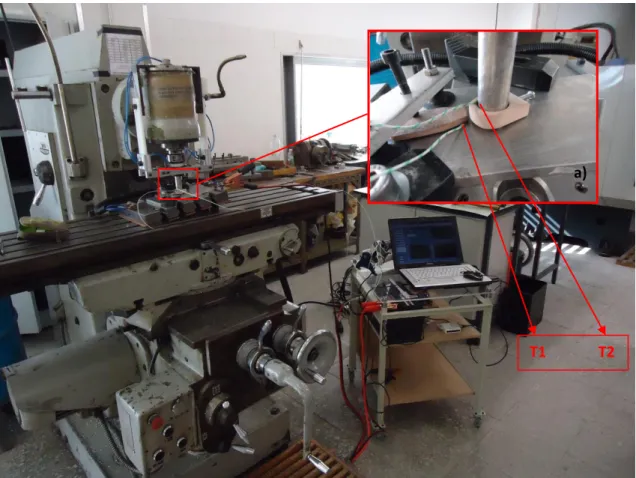
A number of preliminary tests were performed using software Labview to evaluate heat
contribution (ºC), current (A), and Voltage (V) to the process. Figure 3.5 depicts set up. These
tests were performed with no speeds involved, temperature one was registered from
thermocouple one placed in the aluminium plate, and temperature two was registered from
thermocouple two placed in consumable tool. Both thermocouples were placed as close as
34
Figure 3.5 – Analysis montage. (A) Detail from interface between BM and consumable pin.
Figure 3.6 represents the front panel from software Labview, with a number of controls
and graphics corresponding to acquisition of temperature, current and voltage for initial test.
The control panel allows the control of all variants, and is prepared to accommodate AC and DC
current.
Figure 3.6 – Labview front panel.
T1 T2
![Figure 2.4 – Macrographs of cross sections of nugget zone after first pass with different pin profiles [36]](https://thumb-eu.123doks.com/thumbv2/123dok_br/16554036.737271/30.892.134.762.613.954/figure-macrographs-cross-sections-nugget-zone-different-profiles.webp)
![Figure 2.5 – Hardness profiles across FSP stirred zones after three passes with different tool profiles at a rotating speed of 1500 rev/min [36]](https://thumb-eu.123doks.com/thumbv2/123dok_br/16554036.737271/31.892.182.717.174.566/figure-hardness-profiles-stirred-passes-different-profiles-rotating.webp)
![Figure 2.10 - Hardness profile of cross-section in a multi-pass FSP [40].](https://thumb-eu.123doks.com/thumbv2/123dok_br/16554036.737271/34.892.222.673.250.595/figure-hardness-profile-cross-section-multi-pass-fsp.webp)
![Figure 2.11 - Schematic illustration of the groove FSP setup, a) groove, and b) toll aligned with groove [12]](https://thumb-eu.123doks.com/thumbv2/123dok_br/16554036.737271/35.892.144.742.109.304/figure-schematic-illustration-groove-setup-groove-aligned-groove.webp)
![Figure 2.13 - Macrographs of bead cross section, with different placements of grooves [28]](https://thumb-eu.123doks.com/thumbv2/123dok_br/16554036.737271/36.892.159.745.98.761/figure-macrographs-bead-cross-section-different-placements-grooves.webp)
![Figure 2.14 - Schematic representation of the drilled holes in surface reinforcing [6]](https://thumb-eu.123doks.com/thumbv2/123dok_br/16554036.737271/37.892.149.739.120.498/figure-schematic-representation-drilled-holes-surface-reinforcing.webp)
![Figure 2.15 - Variation of Brinell hardness in as-cast, FSPed A356 and composite samples [27]](https://thumb-eu.123doks.com/thumbv2/123dok_br/16554036.737271/39.892.203.686.107.405/figure-variation-brinell-hardness-cast-fsped-composite-samples.webp)
![Figure 2.17 - Microhardness values of specimens FSPed a) without SiC particles and b) with SiC particles in different traverse speeds [12]](https://thumb-eu.123doks.com/thumbv2/123dok_br/16554036.737271/40.892.256.643.252.872/figure-microhardness-values-specimens-particles-particles-different-traverse.webp)
![Figure 2.20 - Tensile properties of the composites and FSP materials produced by different passes [25]](https://thumb-eu.123doks.com/thumbv2/123dok_br/16554036.737271/43.892.136.779.192.667/figure-tensile-properties-composites-materials-produced-different-passes.webp)