Pedro Miguel Amado Rodrigues Leonardo
Licenciado em Engenharia Informática
Child Programming: An adequate Domain
Specific Language for programming specific
robots
Dissertação para obtenção do Grau de Mestre em Engenharia Informática
Orientador :
Vasco Miguel Moreira Amaral,
Prof. Auxiliar,
Universidade Nova de Lisboa
Júri:
Presidente: Doutor Francisco de Moura e Castro Ascenção de Azevedo
Arguente: Doutor André Leal Santos
iii
Child Programming: An adequate Domain Specific Language for program-ming specific robots
Copyright cPedro Miguel Amado Rodrigues Leonardo, Faculdade de Ciências e Tec-nologia, Universidade Nova de Lisboa
Acknowledgements
I would like to express my appreciation for all of those who have helped and cooperated with me in the past academic years. I need to highlight that without their support, all of this work would have not be the same.
To Professor Dr. Vasco Amaral, who I have sought for advice and guidance in this dissertation development, I want to share my greatest gratitude. Thank you for your effort in helping me in this chapter of my academic life.
A thankful note of appreciation is given to Artica enterprise group for sharing their knowledge and creativity. Especially for André Almeida and Guilherme Martins, I want to show my appreciation for allowing the use of your robot, Farrusco. I have earned a great perspective in our technological world thanks to you.
To Colégio Campo de Flores and Jardim Escola Natel, I want to show my thankfulness for conceding the opportunity to perform this scientific study.
I want to show my thankfulness to Catarina and Ricardo for lending me their lan-guage ArduinoFlow, helping me in this study.
My mother Teresa, father Gabriel and brother Nuno had a tremendous importance for the development of this work. Here, I want to share my deepest thanks for the en-couragement that you gave me since the beginning of my life. Nancy as well, I want to thank you for your help, for giving me confidence and being so supportive during my academic chapter.
I would like to thank to my friends André, Cristiano, Fábio and João for accompany-ing me in this stage my life.
Abstract
Due to the limited existence of dedicated robot programming solutions for children (as well as scientific studies), this work presents the design and implementation of a vi-sual domain specific language (DSL), using the Model-Driven Development approach (MDD), for programming robotics and automaton systems with the goal to increase pro-ductivity and simplify the software development process. The target audience for this DSL is mostly children with ages starting from 8 years old.
Our work implied to use the typical Software Language Engineering life cycle, start-ing by an elaborate study of the user’s profile, based on work in cognitive sciences, and a Domain analysis. Several visual design paradigms were considered during the design phase of our DSL, and we have focused our studies on the Behavior Trees paradigm, a paradigm intensively used in the gaming industry. Intuitive, simplicity and a small learn-ing curve were the three main concerns considered durlearn-ing the design and development phases.
To help validating the DSL and the proposed approach, we used a concrete robotic product for children built with the Open Source Arduino platform as target domain. The last part of this work was dedicated to study the adequacy of the language design choices, compared to other solutions (including commercial technologies), to the target users with different ages and different cognitive-development stages. We have also studied the ben-efits of the chosen paradigm to domain experts’ proficient on robot programming in dif-ferent paradigms to determine the possibility to generalize the solution to difdif-ferent user profiles.
Resumo
Devido à existência limitada de soluções dedicadas à programação de robôs para cri-anças (tal como estudos científicos), este trabalho apresenta o desenho e implementação de uma Linguagem de Domínio Específico (LDE) visual, utilizando a abordagem de De-senvolvimento orientado a Modelos, para a programação de robots e sistemas autóno-mos, com o objetivo de aumentar a produtividade e simplificar o processo de desenvol-vimento desoftware, tendo como público-alvo crianças que se insiram num grupo etário a partir dos oito anos.
O nosso trabalho aplica o ciclo de vida característico na Engenharia de Software e Lin-guagens de Programação, estudando o perfil dos utilizadores alvo, baseado em trabalhos de ciências cognitivas e análise de Domínio. Estudou-se os diversos paradigmas visuais para a fase de desenho da nossa LDE, destacando-se asBehavior Trees, sendo este um pa-radigma bem-sucedido e intensamente utilizado na área dos videojogos. Dado o perfil dos utilizadores, os principais objectivos a manter durante as fases de desenvolvimento e desenho da linguagem são simplicidade e uma curva de aprendizagem reduzida.
De forma a validar a LDE proposta, utilizámos um produto robótico para crianças, construído sobre a plataformaOpen SourceArduino. A última fase deste trabalho foi de-dicada ao estudo das decisões tomadas no desenho da linguagem, comparando-a com outras soluções (incluindo tecnologias comerciais) numa avaliação empírica com os utili-zadores alvo. Desta forma, foi possível observar qual o paradigma visual mais adequado para crianças pertencentes a um respectivo grupo etário. Igualmente, analisámos os be-nefícios deste paradigma com peritos no domínio da robótica, de forma a determinar a solução desenvolvida para diferentes perfis de utilizadores.
Contents
1 Introduction 1
1.1 General Introduction . . . 1
1.2 Problem Description and Motivation . . . 2
1.3 Context . . . 3
1.4 The solution . . . 4
1.5 Language Validation . . . 4
1.6 Dissertation organization . . . 4
2 Software Languages 7 2.1 Modeling Languages . . . 7
2.2 Model Driven Development . . . 8
2.3 Domain Specific Languages . . . 8
2.4 DSLs Development Methodologies . . . 9
2.4.1 Modeling and Metamodeling . . . 9
2.4.2 Model transformation . . . 9
2.4.3 Code generation . . . 10
2.4.4 DSL usability evaluation . . . 10
2.4.5 Languages metamodeling Workbench . . . 12
2.5 Visual Languages Paradigms . . . 12
2.6 Summary . . . 17
3 Entertainment and Education Technologies for Children 19 3.1 Lego MindStorms . . . 19
3.2 Scratch . . . 20
3.3 Visual Programming Languages for Arduino . . . 21
3.3.1 Scratch for Arduino . . . 22
3.3.2 ModKit . . . 22
3.3.3 Amici . . . 23
3.3.5 Minibloq . . . 25
3.4 Software Languages for Robots . . . 25
3.5 Summary . . . 29
4 Domain Analysis 31 4.1 User Profile . . . 31
4.2 Case study . . . 34
4.2.1 Arduino Platform . . . 35
4.3 Domain Model . . . 36
4.3.1 Robotic Terms and Concepts . . . 38
4.3.2 Domain Model Specification . . . 39
5 Language Design 41 5.1 Metamodel . . . 41
5.1.1 Abstract Syntax – Relations and Properties . . . 42
5.2 Concrete Syntax . . . 46
6 Implementation 49 6.1 Development Process . . . 49
6.2 Editing the metamodel with EMFATIC and Eugenia tools . . . 51
6.3 Code generation . . . 51
6.3.1 Behavior Tree data structure . . . 52
6.3.2 Generating code . . . 53
6.4 Editor . . . 55
7 Evaluation Process 57 7.1 How to evaluate . . . 58
7.2 Identify Visualino’s goals . . . 58
7.3 Experiments general procedure . . . 59
7.4 Prepared Material for the experiments . . . 62
7.4.1 Slides . . . 62
7.4.2 Exercises . . . 63
7.4.3 Questionnaires . . . 66
7.4.4 Working equipment and environment . . . 72
7.5 Experiments Process . . . 74
7.5.1 Pilot Session . . . 74
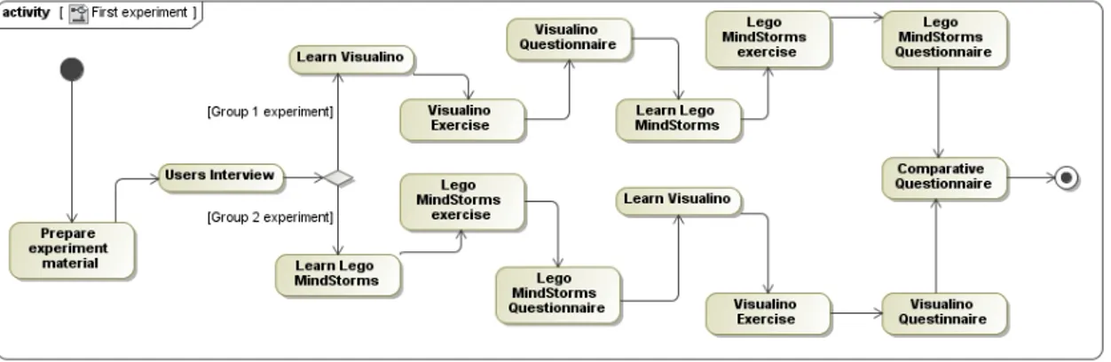
7.5.2 The First experiment . . . 74
7.5.3 The Second experiment . . . 76
8 Results Analysis 81 8.1 Results from the first experiment . . . 81
CONTENTS xv
8.2.1 Group 1 experiment . . . 89
8.2.2 Group 2 experiment . . . 92
8.3 Threats to validity . . . 94
8.4 Conclusion of the analysis . . . 95
9 Domain-experts language validation 97 9.1 Domain experts profiles and Evaluation Process . . . 97
9.1.1 Learning phase . . . 98
9.1.2 Exercise contents . . . 98
9.1.3 Questionnaire . . . 99
9.2 Results analysis . . . 100
9.3 Experiment final remarks . . . 102
10 Conclusions 103 10.1 Dissertation Summary . . . 103
10.2 Contributions . . . 103
10.3 Future Work . . . 104
A Appendix 109 A.1 Slides used for each experiment . . . 109
A.1.1 Visualino slides . . . 109
A.1.2 Lego MindStorms slides . . . 112
List of Figures
1.1 Arduino Board . . . 3
2.1 DSLs’ usability evaluation process [11] . . . 11
2.2 Visual Programming Languages paradigms . . . 13
2.3 Dataflow paradigm example, describing a robot behavior . . . 14
2.4 Workflow paradigm example, describing a robot behavior . . . 15
2.5 Statechart paradigm example, describing a robot behavior . . . 15
2.6 Behavior Tree paradigm example, describing a robot behavior . . . 16
3.1 Lego MindStorms’ Programming Language . . . 20
3.2 SampleScratchscript . . . 21
3.3 Scratch for Arduinosample script . . . 22
3.4 Modkitsample script . . . 23
3.5 Amici example program . . . 24
3.6 Ardublock example program . . . 25
3.7 Minibloq example program . . . 26
4.1 Farruscorobot . . . 35
4.2 Feature Model . . . 37
4.3 Domain Model . . . 39
5.1 Node and links Metamodel fragment . . . 42
5.2 Control Nodes Metamodel fragment . . . 43
5.3 Leaf Nodes Metamodel fragment . . . 44
5.4 Enumerated types from the metamodel . . . 44
5.5 Components Nodes Metamodel fragment . . . 45
5.6 Sensing Nodes Metamodel fragment . . . 46
5.7 Complete Metamodel . . . 46
6.2 Devices involved in the DSL . . . 50
6.3 Editor Interface . . . 56
7.1 General process for the DSL evaluation . . . 61
7.2 Solution for the Visualino exercise . . . 64
7.3 Solution for the Lego Mindstorms exercise . . . 65
7.4 Solution for the ArduinoFlow exercise . . . 65
7.5 Visualino Questionnaire . . . 67
7.6 Lego Questionnaire . . . 68
7.7 ArduinoFlow Questionnaire . . . 69
7.8 Comparative Questionnaire . . . 71
7.9 Groups that composed the first experiment . . . 74
7.10 Process taken for each group . . . 75
7.11 Groups that composed the second experiment . . . 76
7.12 Process taken for each group . . . 79
8.1 Group 1 time spent in the exercises for each language – started with Visualino 83 8.2 Group 2 time spent in the exercises for each language – started with Lego MindStorms . . . 83
8.3 User program snapshot containing a condition implementation error . . . 84
8.4 User program snapshot containing a correct implemented condition . . . 85
8.5 User program snapshot containing a condition implementation error in Lego 85 8.6 User program snapshot containing a well-implemented condition in Lego MindStorms . . . 86
8.7 Comparative questionnaire answer by each Group . . . 86
8.8 Questionnaires answers from both groups . . . 87
8.9 Descriptive statistics – Wilcoxson results . . . 88
8.10 Answers regarding blocks ease of use for each Language . . . 88
8.11 Group 1 time spent in the exercises for each language – started with Visualino 90 8.12 Questionnaires answers from Group 1 . . . 91
8.13 Answers regarding blocks ease of use for each Language . . . 92
8.14 Group 2 time spent to complete ArduinoFlow’s exercises . . . 93
8.15 Questionnaires answers from both groups . . . 94
9.1 Time spent in the exercise for each language and domain expertise profile 100 9.2 Blocks appreciation . . . 101
9.3 Visualino general appreciation . . . 101
A.1 Visualino’s slides – part 1 . . . 109
A.2 Visualino’s slides – part 2 . . . 110
A.3 Visualino’s slides – part 3 . . . 111
LIST OF FIGURES xix
A.5 Lego MindStorms’ slides – part 1 . . . 112
A.6 Lego MindStorms’ slides – part 2 . . . 113
A.7 Lego MindStorms’ slides – part 3 . . . 114
A.8 Visualino’s slides – part 1 . . . 114
List of Tables
3.1 Robot Interaction Languages . . . 27
3.2 Robot Languages characteristics . . . 28
3.3 Robot Languages characteristics . . . 28
3.4 Robot Language Tool features . . . 28
3.5 Robot Languages Tool features . . . 29
4.1 Piagetian Stages of Development . . . 32
4.2 Children characteristics . . . 33
5.1 Control Nodes concrete syntax . . . 47
5.2 Leaf Nodes concrete syntax . . . 48
5.3 Links concrete syntax . . . 48
7.1 First experiment evaluation . . . 60
7.2 Second experiment evaluation . . . 61
7.3 Hardware characteristics used in the experiments . . . 72
7.4 Software programs used in the experiments . . . 73
7.5 Robots Characteristics . . . 73
7.6 User Profile . . . 76
7.7 Characteristics from each group . . . 76
7.8 Group 1 User Profile . . . 77
7.9 Technological background from group 1 . . . 77
7.10 Group 2 User Profile . . . 78
7.11 Technological background from group 2 . . . 78
8.1 Group 1 time spent for each task example in Visualino . . . 82
8.2 Group 1 time spent for each task example in Lego MindStorms . . . 82
8.3 Group 2 time spent for each task example in Lego MindStorms . . . 82
8.4 Group 2 time spent for each task example in Visualino . . . 82
8.6 Group 1 time spent for each task example in Lego MindStorms . . . 90 8.7 Group 2 time spent for each task example in ArduinoFlow . . . 92
1
Introduction
1.1
General Introduction
Nowadays, we are witnessing a strong presence of increasingly complex system designs in several areas, commonly called cyber physical systems [1] (CPS) that combine both computer systems and electronic elements. These projects, also called embedded sys-tems, can be found in the Aerospace Industry, Telecommunications, Automotive, Chemi-cal, Civil, Energy, Health, Manufacturing, Transportation, Entertainment and Education. Typically, these systems are intended for different users profiles, from the most so-phisticated, deep technology knowledge and programming skills, up to less advanced – adults to children. Systems complexity is increasing and heavily dependent on its ac-tual operating domain. These require domain experts to perform increasingly complex tasks and activities. When developing these kind of systems, it is essential to do atradeoff between usability aspects and adequacy of user control to operate the systems involved and complex tasks they can perform.
Interfaces design, and especially languages suitable to user profiles, has been an an-swer to achieve this tradeoff. However, developing these languages is a recent activity in computer engineering that raises many issues related to the systematic approaches, development tools, re-use of components strategy, validation etc..
Robotics’ area is a branch of technology that deals with different electronic compo-nents. Each one of those components requires specific programming concepts that will define its job with the surrounding environment. Electronics prototyping field has in-numerous technologies such as Arduino1 and Lego MindStorms2. These technologies
1http://arduino.cc/
seek to relate programming concepts with hardware expertise, in order to create interac-tive objects or environments. Artists, designers and creainterac-tive people – which may have no technological background – are the main target users for these platforms. However, given the current state of technology, the user must have some experience with program-ming concepts, as for example the Arduino language resembles C/C++ languages, and has its own programming tool for compilation and upload code to the Arduino board.
Due to these well-succeeded achievements in electronic engineering field that Ar-duino brought to the robotic community, various projects have been created within el-ementary and high school environment. Arduino became an additional working and creative platform in education[2] [3].
Programming concepts along with Robotic ideas gave benefits in children learning process, mainly due to interactive aspects since students have the opportunity to observe the code that they develop, such as a simple blink of an LED on the Arduino board.
1.2
Problem Description and Motivation
The current state of the art in programming technologies of rover robots for children is still greatly excluding the younger ages because it is still hard for them to program in a textual language with a complex syntax full of programming languages concepts.
However, to design an appropriate domain specific language for children is far from being a trivial task. There is no unique profile, and several factors related mostly to age, like the maturity level, that can influence widely in the design.
The pertinent question it arises is if it is possible to build a dedicated DSL, that re-moves the programming details, to control a rover robot, and at the same time allows children to easily get acquainted with it and have still the possibility to program complex behavior?
The objective of this work is to study and implement, in the domain of Robotics ap-plications, the adequate language constructs and metaphores for a DSL designed for children. Since the DSL is intended to be used in an education environment (primary and secondary), visual elements and textual concepts should be appropriate to the target users. Low learning curve is a mandatory requirement such as productivity increment in creating new programs.
1. INTRODUCTION 1.3. Context
1.3
Context
The DSL development counted with a Robot consisting with common components and functions in the robotic area. The work is being developed under a collaboration between the group ASE CITI/Departamento de Informática and Artica, a company that special-izes in development of robotic and audio-visual solutions. Artica provides the Robot and case studies with children that will help evaluate the DSL usability. Farruscois the name of the provided robot which is composed by an Arduino board – attached to this board, there is a set of sensors and actuators components. This robot own a typically physi-cal configuration for the components set, although it is possible to change it. Farrusco’s consist on the following components:
• An Infra-red Distance sensor;
• Two collision detectors sensors, namedbumpers;
• Two motors for each wheel;
• A motor named Servo, that actuates under the Distance Sensor;
• A simple LED over the Arduino board.
The Arduino board is showed in figure 1.1, with itspinsfor sensors and actuators con-nections.
Figure 1.1: Arduino Board
Farrusco, being the chosen robot for the development of this work, is directed to per-sons with low levels of knowledge in programming and electronic areas. Thus, when designing a simple behavior for Farrusco, e.g. activate both wheel motors so it can move forward, it is necessary some time and effort taken by users. The time spent in learning robotic and programming concepts could also add low levels of motivation for the user.
1.4
The solution
In order to develop a suitable solution, it was necessary to study and analyze the current domain of rover robots for children. This analysis encompasses the study of different user profiles that represent possible target users for the developed DSL. The robot domain had to be limited due to its extensive area and the diversity of concepts and technologies it contains.
The different types of visual programming paradigms were analyzed as well, so we could properly adapt the DSL’s usability to the user profiles and the specific robotic do-main. Behaviors trees, dataflow and workflow diagrams were the visual paradigms con-sidered in the development of the DSL.
According to the domain experts point of view, we decided to study and analyze the behavior tree paradigm as a visual language, since it has a great success in other domain areas (e.g, coordinating autonomous agents in video games), addressing its applicability to younger age groups. In this way, we access what could be the best paradigm for programming robots, both for children of different ages and at the same time determine the increasing productivity of using such paradigm with the domain experts.
Through a Model-Driven develoment (MDD) approach, it was possible to formalize and create the DSL metamodel covering the specific details from the domain analysis. It also provides an agile development considering possible DSL improvements made along the research. Eclipse workbench and Eugenia tool were the technologies used for the DSL development.
1.5
Language Validation
A great effort was invested in planning and organizing the empirical studies required to evaluate the design of the language. Namely, we looked at the visual paradigms, and design constructs of the language.
As we will describe in the next chapters, we achieved a set of conclusions and learnt lessons that serve as input for the design of a future new evolution of the proposed lan-guage in this document.
1.6
Dissertation organization
The dissertation is organized in ten sections:
On chapter 2 the state of the art of this project is analyzed. It includes the themes of Games Engines, Augmented Reality, Visual Programming Languages, Modeling Lan-guages and DSLs.
1. INTRODUCTION 1.6. Dissertation organization
also compares languages and robotic tools for children, highlighting important as-pects for each technology;
• On chapter 3 is presented the state of the art, which shows technologies involving the robotic area, and programming tools for children;
• Chapter 4 shows the domain analysis and the proposed solution for the DSL devel-opment. It also describes the user profile characteristics;
• Chapter 5 presents the language design details.
• On Chapter 6 are presented implementation details and the process taken for the DSL development;
• Chapter 7 introduces the evaluation process for the DSL;
• Chapter 8 describes the results taken from the case studies presented in the previous chapter;
• Chapter 9 contains the language evaluation and validation with Arduino domain experts;
2
Software Languages
In recent years, there has been a growing number of languages used for creating and drawing software, as the interest in engineering languages.
Likewise, the use and creation of DSLs have become increasingly dominant. DSLs focus and describe certain aspects of a system or a particular software fraction. Modeling languages have become very important in model-driven development context. The use of models and metamodels is part of modeling languages. Without the existence of multiple programming and modeling languages, certainly the MDD1 approach would not have
much relevance.
There are many similarities between modeling and programming languages such as:
• Both are used to describe software;
• After transformed and/or compiled, both have to be executed.
2.1
Modeling Languages
Domain specific models are designed to increase the abstraction level that programming languages provide, using concepts that identify the domain of a given problem [4]. With this approach, it is possible to generate final applications produced using a programming language. These applications correspond to the model representing the abstract form of the problem domain. End applications’ generation process is usually supported by a frameworkorAPIthat uses a specific domain generator [4].
A modeling language can be used to express knowledge or systems in a specific struc-ture, defined by a consistent set of rules. The language can be either graphical or textual.
A language is composed by a syntactic notation, which may contain an infinite number of elements. This corresponds to a language’s abstract syntax, which defines the con-cepts and how they can relate with each other. The concrete syntax defines the concon-cepts’ presentation, together with the semantics that gives meaning to those concepts [5].
2.2
Model Driven Development
Model-Driven development approach, also known as Model-Driven architecture, is a technique or a set of methods for software development, that is a trademark of Object Management Group in the scope of the Model Driven Architecture2. The modeling
con-cepts refer to domain concon-cepts instead of mapped into broad technological notions, so full potential of Model Driven Development can be achieved. Models are essential arti-facts that describe specific concepts for a target domain. Those contain abstract represen-tations of the knowledge that manage a certain domain [6]. Through MDD, a system is defined by a model that is in conformity with a metamodel.
A model contains problems and concepts that vary by domain. Distinct domains require different languages. DSLs came to solve this problem, allowing the use of domain concepts on the models’ specification [7].
2.3
Domain Specific Languages
Domain Specific Languages have the same characteristics as any other language com-posed by three essential elements:
• Abstract syntax describes the language structure, with its properties, rules and re-lations;
• Concrete syntax explains the language notations, i.e., it describes how language’s elements are represented (visual, textual or a mixed);
• Language semantics defines the concepts’ meaning described in abstract syntax.
A domain is limited by an area of interest and knowledge, characterized by a group of concepts and terms understood by persons of that field. Domain analysis is a fundamen-tal piece for a DSL development. Without the domain concepts clear, it is not possible to understand which are the important requirements needed to implement and design the DSL. Domain experts give important information so it is possible to express problems and concepts at a higher level of abstraction. This can be achieved trough a careful anal-ysis of the domain’s features. A Feature model can represent those domain concepts and features in a form of a tree. It describes how each concept relates to another.
2. SOFTWARELANGUAGES 2.4. DSLs Development Methodologies
The conceptual distance between the problem area and the language used is reduced. The DSL presents concepts that are familiar to the target users within their working do-main, instead of general computer terms [8]. The DSL is defined through concepts and features specific to the problem domain, which improve the usability and comprehen-sibility for the end-users. The main goal for any DSL is its expressiveness power on its target domain [9]. Solution details are hidden from the user, and domain experts do not need to worry about those specific details. This dramatically reduces the development time for a target solution.
Domain specific modeling relates the final application characteristics with domain concepts[6]. However, this technique is not suitable when the application domain is not entirely known.
2.4
DSLs Development Methodologies
As previously said, domain analysis is one of most important factors for starting to de-velop a DSL. This section describes common methodologies used in DSLs dede-velopment.
2.4.1 Modeling and Metamodeling
Modeling is used for designing systems, making their comprehension easier. At the same time, they also specify the required functionalities for the target system. Models are used for designing purposes, this happens when the problem domain requirements are too complex to represent in textual code. Thus, models are used to add an higher abstraction layer and hide code implementation.
Metamodeling is a formalism to specify software languages [10]. Metamodeling is the gathering of a collection of concepts within a certain domain. A metamodel is a model used to specify a language [10]. Abstract syntax is defined through a metamodel. It de-scribes language’s rules, properties and relations [10]. This also applies to the concrete syntax of the language. Any model that specifies language’s details and concepts is con-sidered as a metamodel.
The model is an abstraction of the actual real world concept. Models are commonly represented with elements, their connections and special symbols. Modeling provides: a cleaner architecture presentation; conceptual simplicity; efficiency implementation; scal-ability and flexibility [7].
2.4.2 Model transformation
A model transformation is a function from abstract syntax models I1, .., In to abstract syntax models O1, .., Om [10]. These transformations are defined in the syntax struc-ture metamodels. This could be achieved through transformation languages, e.g., ATL3,
Stratego4. Through rules and mapping functions defined in the elements from the origi-nal model, it is possible to create a new model based on the old one.
These languages are used in the relationship between the domain metamodel and the framework metamodel, used to generate code. A model’s instance could be transformed to a verification model that evaluates the instance model’s properties.
2.4.3 Code generation
Code generation can be regarded as a form of semantics [10]. The target language, usu-ally has a lower abstraction level than the original. This requires the construction of a code generator. There are several tools designed for this purpose, such as JET5, Xpand6, EGL 7. A code generator parses the instance of the model as a tree, and generates the
corresponding code blocks. The generator is implemented and prepared to translate the model to the chosen programming language code.
2.4.4 DSL usability evaluation
DSLs are a way to increase productivity, using concepts of the problem domain. Typically, DSLs target users do not need a deep knowledge in programming languages concepts. DSLs came to fill the gap between domain experts and computational solutions plat-forms [11]. Human/Computer Interaction presents the same objectives as DSLs. Both should increase the users’ efficiency, while performing their duties without having to cause extra organizational costs [11]. The language engineer must get involved in the target domain, so he can study and analyze specific problems, concepts and terms. At the same time, the engineer developer shall have the ability to build the target language [11]. The evaluation of User Interfaces is related with a qualitative software characteristic named Usability. It is defined by quality standards in terms of achieving the Quality in Use8. Usability is defined as: "the extent to which a product can be used by specified users
to achieve specified goals with effectiveness, efficiency and satisfaction in a specified context of use" [12]9. There are forms to evaluate usability such as:
• Formally through some analysis techniques, taking models and simulations, e.g measuring the elapsed time to complete a given task.
• Automatically by a computerized procedure. This is possible when application prototypes are available.
• Empirically, through experiences where users test the application. This technique is recommended at all stages of development;
4 http://strategoxt.org/ 5 http://www.eclipse.org/modeling/m2t/?project=jet 6http://www.eclipse.org/modeling/m2t/?project=xpand 7http://www.eclipse.org/proposals/egl/
8ISO/IEC 9126 Quality Standards. 2004. http://www.iso.org/iso/
2. SOFTWARELANGUAGES 2.4. DSLs Development Methodologies
• Heuristically, auto evaluating the product, based on self-judgments.
Building a new DSL, three main design objectives are required[11]:
• The language should capture the domain expressivity;
• It must ensure compliance with the standards of a given domain;
• It should overcome previously identified problems in the domain.
DOMAIN ENGINEERING
Specify context of use & user and organizational requirements
Elect domain concepts and identify usability requirements
and meaning of attributes in given context for user profiles
USER & CONTEXT
MODEL
DESIGN THE LANGUAGE
Produce design solutions
Find which attributes are meaningful for domain concepts
and relate them by their identified dependency, find metrics that will indicate it
LANGUAGE MODEL
IMPLEMENTATION & TESTING
Evaluate design against requirements
Calculate metrics and check conformance with requirements,
create user or expert based evaluations FIND DISTANCE BETWEEN MODELS Plan the process Conceptual distance is minimized
Figure 2.1: DSLs’ usability evaluation process [11]
As proposed in [11], the usability evaluation should be done during the DSL develop-ment. According to this proposal, usability requirements should be gathered/identified during Domain Engineering stage and at the same time, domain concepts are collected. During theDesign The Language stage, each domain concept should be identified as its relevance within the specific domain. InImplementation and Test stage, the language en-gineer should validate the usability requirements’ list. Each stage is depicted in figure 2.1.
2.4.5 Languages metamodeling Workbench
Metamodeling tools allow a simplified development process of a DSL. These tools offer features to develop the language metamodel, establishing relations, properties and rules to the models. Visual editor is created with these tools as well, so end-users could pro-duce new models and generate the corresponding code. There is a wide choice of tools for the DSL development, such asEclipse Modeling Framework10that usesGraphical Mod-eling Framework 11 to design models. Microsoft has one DSL development tool, named Visual Studio Visualization and Modeling SDK (the old DSL Tools)12. It features the same
general functionalities asGraphical Modeling Framework.
Eugenia13 is a tool for Eclipse Workbench that generates automatically the visual ed-itor (GMF) and its corresponding concepts, through a single annotated metamodel, the Ecorefile.
2.4.5.1 Workbench selection
The chosen metamodeling workbench for the DSL implementation wasEugeniaforEclipse. This tool simplifies the generation process of models to implements a GMF editor [13]. It offers an extensive list of functionalities for developing the DSL. Creating a new GMF ed-itor from scratch brings some challenging aspects, since it has many configurable details. Eugenia provides a higher-level abstraction, hiding the complexity of GMF [6]. These characteristics allow a rapid prototyping phase, so users can be involved earlier in order to achieve their feedback.
2.5
Visual Languages Paradigms
A visual programming language allows the user to implement programs, through the manipulation of visual elements or objects. This manipulation is performed in a visual way, allowing the user to understand quickly programming mechanisms, increasing their accessibility to new systems [14]. Users with no programming background may imple-ment programs in a simpler form.
A visual programming language is represented by a meta-model, as opposed to tex-tual programming languages. These textex-tual languages representation is made through grammars practices [10]. Visual languages are classified according to the expression type used. They can use expressions based on forms, icons, diagrams or even the combination of these techniques. Figure 2.2 depicts visual programming language paradigms, each one with their own type of visual expression.
10http://www.eclipse.org/modeling/emf/
11http://www.eclipse.org/modeling/gmp/
12http://archive.msdn.microsoft.com/vsvmsdk
2. SOFTWARELANGUAGES 2.5. Visual Languages Paradigms
Figure 2.2: Visual Programming Languages paradigms
Iconic / Graphical Elements based VPLs
The visual programming languages based on icons or graphical elements, hold figures (icons) denoting objects in the program with their own corresponding function or real world representation [15]. Tile-based languages are represented by graphical tiles (el-ements) which can be manipulated by the programmer as building blocks [16]. Typi-cally this type of VPLs14 programs are created by building a vertical sequence of tiles, maintaining a sequential execution from top to bottom. They also present spatial con-cerns, since each tile is directly connected to its corresponding attached tile – there are no edges or arrows to describe icons/nodes relationships. The following chapter shows several languages which apply this visual programming paradigm such as Scratch pro-gramming language. Icons and visual artifacts are usually combined with other language paradigms, since they are able to represent specific problem domain aspects [14].
Form based VPLs
Form-based paradigm is similar to a spreadsheet, in which the form is typically shaped as a grid and its contents are represented by cells. Forms corresponds to an abstraction of conventional paper forms, which facilitates non-experts users to organize data into a structured representation (e.g, tables) [15]. The user programs by creating a form and specifying its contents, commonly seen in commercial spreadsheets [14]
Diagrammatic VPLs
Diagrammatic VPLs are based on nodes (which may represent program states or func-tions), and edges (corresponding to transitions or arrows which symbolize a flow of work). We may characterize the diagrammatic VPLs in other three sub categories – Flowcharts, StateCharts and Behavior Trees. These are interesting to study since they
can represent states, work flows or even data flow processing, relevant to describe au-tonomous agents programs/behaviors. Flowcharts depicts algorithms or processes, through the step boxes ordered by arrows which arrange the program structure and its corre-sponding flow – activities and decisions are expressed through this paradigm nodes.
Dataflow
Dataflow paradigm provides a view of computation which shows the data flowing from one filter function to another through the representation of arcs [17]. In theDataflow exe-cution model, a program is represented by a directed graph where the nodes of the graph represent primitive instructions (e.g arithmetic or comparisons functions). Directed arcs between the nodes represent the data dependencies between the instructions [18]. This programming paradigm allows the representation of control-flow or data structures exe-cution.
Labview15 language and Openwire library16are software solutions which apply the dataflow paradigm in their programs.
Figure 2.3: Dataflow paradigm example, describing a robot behavior
WorkFlow
Workflows are a similar way to express information-processing scenarios. A Workflow is defined by nodes or blocks that represent data processes and connections, which char-acterizes the link between those nodes. The links represent the relationships that apply constraints on the execution model. Figure 2.4 shows an example of aworkflowprogram. Typically, Workflow models represent operations or sequence of operations which may correspond to a single entity (e.g. an electronic component). This is the main difference between Workflow and Dataflow paradigms. Dataflow paradigm define operations with input and outputs [17] clearly separated – this paradigm defines the structure of a sys-tem through the components which composed it. The Workflow paradigm declares the sequence of operations for a single entity/component.
15http://www.ni.com/labview/
2. SOFTWARELANGUAGES 2.5. Visual Languages Paradigms
YAWL17is an example of a workflow system, based on a modeling language which uses the Workflow paradigm to handle transformations, resourcing requirements and control-flow dependencies.
Figure 2.4: Workflow paradigm example, describing a robot behavior
Statechart
Figure 2.5: Statechart paradigm example, describing a robot behavior
Statecharts is another diagrammatic visual programming paradigm based on finite state automata. The states diagrams are used to represent behaviors of a system, describing the current state of the system itself, and the arrows define the transitions/behaviors between states. Figure 2.5 depicts an example of this visual programming paradigm, characterizing a robot behavior; in this particular case, its own speed and direction.
Statechart [19] visual language uses the conventional state diagrams to specify soft-ware requirements.
Behavior Trees
A different way to represent a visual language may be throughBehavior Trees. These act as an alternative to state machines and are composed by an hierarchy of behaviors, with an objective to fulfill. Each node may have a specification that determines how the actions of its children will be executed, which may be in parallel or sequentially. Children return its status to the parent node, and this successively until the root of the tree [9]. A behavior tree is a structure containing behaviors organized in a tree. It is composed by a com-plex behavior which is mapped into smaller simple behaviors through its branches [20]. This descending order of complexity provide a structured manner to define complex be-haviors through simple tasks hierarchically defined. The behavior tree concept is com-monly used to encode game artificial intelligence agents [21] by gaming and artificial intelligence domain experts, in a modular, scalable and reusable manner [22] – valuable characteristics in a DSL.
Figure 2.6 shows a simple robot behavior through theBehavior Treeparadigm. It con-tains two control nodes: Parallel and Decide nodes. These two nodes control thebehavior tree’sflow and execution states. Parallel node simply runs all of its children at the same time. The decide node decides which children should run at a specific time and situation. Leaf nodes represent the most primitive actions that could be taken by an agent.
Figure 2.6: Behavior Tree paradigm example, describing a robot behavior
2. SOFTWARELANGUAGES 2.6. Summary
Visual Programming Language remarks
There are significant differences between visual programming language concepts and textual languages. It is, therefore, a different way of programming, whether for an ex-perienced programmer or a person who has no background/programming knowledge. The programmer can focus the solution through visual elements which handle lower information density. However, this type of programming languages also comprise neg-ative aspects – e.g., the language’s implementation area/surface tends to increase over complex solutions, making its analysis and reading difficult to achieve. Containersare blocks that group several developed elements of code. Conversely, they also prevent the occurrence of syntax errors, a fairly common problem in textual languages and the auto-matic parallelization of code, an important characteristic which is one of the most difficult challenges presently [18]. Empirical studies also demonstrated that visual languages are more intuitive and quick to understand when compared to textual languages [23].
2.6
Summary
In this chapter we analyzed Modeling and Domain-Specific Languages along with the Model Driven approach. We also showed typical methodologies and the development process to implement a new DSL. It is important to highlight the iterative process within the DSL implementation and design, in order to evaluate its usability and identify pos-sible language flaws or domain concepts that could mislead the target user. The domain analysis provides the essential specific concepts and knowledge necessary to support the language design.
3
Entertainment and Education
Technologies for Children
Children have a desire to explore and experience the physical and conceptual environ-ment [24]. Several technologies have been developed in the areas of Computer Science and Robotics, in order to aid children’s development. Obviously we cannot disregard the works, applications and languages already made in this domain, so we can take it as an advantage in order to study its features, limitations and visual paradigms and further compare those with our DSL. Visual languages introduce programming concepts to chil-dren[25], while Robots perform the developed code in the real world. Children have the opportunity to observe their own developed program, running in a physical robot. The following sections demonstrate languages and current technologies for children, present-ing their goals and objectives.
3.1
Lego MindStorms
Lego MindStormsis perhaps the most known technology in Educational robotics, having children as target users. Several case studies [26] have been done about this technology in order to understand which are the main individual needs of children, when working with robots. Lego MindStorms’ approach is to combine the concepts of hardware and software, so the users could develop and deploy programs containing behaviors which shall be executed by the robot. The robot is built by children, so they could understand connections mechanics and each component’s function, such as sensors and actuators.
as execution control element, e.g loops, conditions, arithmetics, or an actuate block that interacts with the robot components, e.g motors. The sequence of blocks is constructed by a behavior’ flowchart, structuring the program’s blocks. Each block may contain options or arguments to trigger a specific action, e.g. the sound block shows a list of possible sounds that can be played by the robot. Figure 3.1 shows an example made with this programming language.
Figure 3.1: Lego MindStorms’ Programming Language
These robots contain negative factors, like the constant need for recalibration of its sensors and motors. Lego MindStorms’ Tool contains a function to solve this problem. This is one important feature to identify, since calibration is a common problem in the robotic world. The visual language brings appealing icons and figures, but the develop-ment of complex behaviors may become difficult [27]. The increasing number of blocks and the size of the flowchart becomes difficult to analyze and read the program solution. Thus, non-trivial behaviors are difficult to implement in a visual programming language like this.
3.2
Scratch
Scratch1 is a pedagogic programming tool that has children as target users. TheScratch grammar is based on a collection of graphical “programming blocks”, and it aims to teach basic programming concepts in a simpler and creative way. It proposes an easy to
3. ENTERTAINMENT ANDEDUCATIONTECHNOLOGIES FORCHILDREN 3.3. Visual Programming Languages for Arduino
learn approach, through visual elements. In order to avoid syntax errors,Scratchhas no ambiguous syntax or punctuation of traditional textual programming languages, which could lead to user’s frustration and consequent leave of the language [28] [29]. Scratch’s blocks are shaped to fit together only in ways that make syntactic sense. Those blocks represent programming concepts, such as control loop structures (forever, repeat) or con-ditionals. Each type of block suggests how it connects to a different block:
• Loopscontrol blocks are C-shapped suggesting that blocks should be placed inside.
• Blocks that return values are shaped according to the types they return (oval for numbers, hexagons for booleans).
• Conditional blocks have a hexagon-shaped spaces which indicates a boolean is re-quired.
Concepts like parallelization are presented abstractly – launching two sequences of blocks at the same time creates two independent threads that execute in parallel. Scratch main-tains the concepts of basic programming given that its goal is to introduce children the programming concepts and logical reasoning. Figure 3.2 shows a simple script onScratch workbench. Whenever the mouse pointer goes over the game character, it should move 5 steps, followed by a pause of 5 seconds.
Figure 3.2: SampleScratchscript
Implementing games or programs using a visual interface with objects and personal elements, such as photos, icons or figures, increase children motivation and willingness to explore, since the user works on personally-meaningful projects [28]. Thus, the child can create a graphical program, enabling the creation of multiple animations, games and interactive stories.Scratchplaced high priorities in personalization and diversity so chil-dren with widely varying interests could work on projects that they care deeply about. Therefore, project customization is one of the most important features ofScratch[28].
3.3
Visual Programming Languages for Arduino
3.3.1 Scratch for Arduino
Scratch for Arduino2 combines Scratch visual programming language, presented previ-ously, with Arduino’s concepts and features. This tool provides a graphical interface to produce projects for Arduino’s interactive objects, e.g. robots, instead of Scratch’s game character.
Scratchoriginal blocks were adapted to Arduino main functions, such as write and reading for Analog and Digital pins belonging to Arduino board. Figure 3.3 shows a simple project with a sequence of blocks containing Arduino functions, such as pins volt-age control and conditionals blocks together with Arduino sensors information.
This technology has a developed firmware that should be compiled and uploaded to the board before developing a solution. Without this firmware, developed projects are not possible to communicate with Arduino, since the firmware works as a bridge be-tween the computer which has installedScratch for Arduino. Arduino board does not pro-cess any data, it simply actuates motors and delivers sensors information to its attached server/PC. This server processes all the information and decides which Arduino’s mo-tors should activate. If the connection between the devices is made by a physical cable (the link is commonly maintained by USB cable), the robot will only operate within the cable range.
Figure 3.3: Scratch for Arduinosample script
Users’ developed projects are not compiled or uploaded to the board, making it im-possible to maintain the behavior when the connection between the two devices is can-celed. In order to maintain the execution of the developed project, the connection be-tween the Arduino and the attached server, must remain plugged.
3.3.2 ModKit
Modkit3 technology is a similar tool withScratch for Arduino, presented previously.
Con-sequently, it is also based inScratchvisual programming language. It has specific blocks for programming Arduino microcontrollers. Bringing programming concepts to the real
2http://seaside.citilab.eu/scratch/arduino
3. ENTERTAINMENT ANDEDUCATIONTECHNOLOGIES FORCHILDREN 3.3. Visual Programming Languages for Arduino
world is the main goal for this technology, combining robotic concepts with program-ming logical thinking [30]. Children as the target audience forModkit, can develop, com-pile and upload projects to Arduino board, being able to observe the developed behavior in the real world platform.
Blocks’ shape and the workflow programming are similar to Scratch. These blocks have a nomenclature analogous to Arduino’s commands and functions.Modkitfollowed this approach, so that users with earlier Arduino knowledge could be able to fit in quickly to Modkit. Users with no Arduino knowledge would be able to understand these con-cepts, preparing them to program in the original Arduino textual language [30].
Blocks’ shapes suggest the way they fit with each other as previously mentioned lan-guages. This tool runs over any Web browser, allowing automatic updates without users’ configuration. An example of this language and tool is shown in figure 3.4.
Figure 3.4: Modkitsample script
This tool allows to develop Arduino and Arduino compatible software using: graph-ical blocks, traditionally text code. The graphgraph-ical developed program is automatgraph-ically translated to text-based code, so users can observe what the block code would look like in textual form. Therefore, code analyses shall be easier for experienced users.
Modkit specifies Arduino platform as its target domain. Arduino’s world is very broad, containing too many concepts and robotic solutions, makingModkita general so-lution for visual programing projects.
3.3.3 Amici
As opposed to previous technologies, Amici4 has its own graphical interface elements and a new visual way to develop program. It is based on blocks as well, with a program structure similar with Arduino’s projects. The graphical projects developed through this technology can be translated to Arduino textual code. This feature presents the same positive aspects mentioned inModkitlanguage.
Amicidoes not provide a detailed graphical interactivity as the languages presented previously. Figure 3.5 shows a project developed inAmici’s workbench. There are two
Figure 3.5: Amici example program
block’s sequences, SetupandLoop. These two functions characterize the Arduino code –Setup’s sequence is executed only once when the program starts and it initializes vari-ables and pin modes; Loop’s sequence allows the program to change and respond, con-secutively. Arduino textual code is also split in these two functions.
Icons’ shapes suggest which block connects to another, in a simpler form comparing these characteristic with previous languages. Amici focuses on robotic aspects, present-ing blocks with this kind of information, such as LEDs actuators, motors. The input parameters are adapted according to block’s characteristics, i.e. is defined a LED block, its input parameters could beON or OFF. Figure 3.5 shows a LED pin which contains both status (ON and OFF); pin 7, representing a robot’s Servo, takes degrees values as input parameters.
3.3.4 ArduBlock
Ardublock5is another block programming tool for Arduino. It is a plugin for the Arduino IDE, that generates code for Arduino Workbench.
Colorful blocks represent the different graphic programming elements and concepts, such as yellow blocks imply control structures (loop or conditions). Each block has a meaningful shape that defines its connection to others. Complex programs are difficult to implement, since the blocks’ size limits the designing area. There are specific blocks for robotic components, such as Servos and Buzzers.
Figure 3.6 depicts anArdublock program. It shows specific robotic blocks, counting with Servo and Buzzer components. It shows delay function, an Arduino concept and main feature.
Ardublockfeatures the same goals as the previous Visual Languages.
3. ENTERTAINMENT ANDEDUCATIONTECHNOLOGIES FORCHILDREN 3.4. Software Languages for Robots
Figure 3.6: Ardublock example program
3.3.5 Minibloq
This technology6 presents an interface different from all the others, while maintaining the use of blocks for developing programs. The blocks are represented via icons with no textual reference explaining its meaning or purpose. These icons suggest the function performed by the respective block. The pallet contains all language’s blocks, describing each block function and its respective details of use, when the mouse pointer passes over a single element.
All blocks have the same shape (rectangles), and are distinguished by its own color and icon. Minibloqhas robotic specific blocks, such as Motors, Buzzers and Servo. The remaining blocks count with general characteristics from Arduino, like time, pin voltage control (digital or analog), loops, and conditions. Figure 3.7 depicts a program containing pin voltage blocks, which change a LED state every 500 milliseconds (classic blinking behavior).
While developing a solution, it is possible to choose which Arduino board the pro-gram is going to operate. A representative figure contains the board model, indicates pins numbers, actuators and sensors connections.
As the previous languages, this tool also presents the actual Arduino code built through the developed graphical project. This tool presents a new feature – it is possible to com-ment blocks in the project diagram, removing them from the execution model. This char-acteristic allows a better control of the developed program, for analyzing and reading purposes.
3.4
Software Languages for Robots
This section analyses a group of applications for robots, that use visual elements and some functionalities to specify their programs. The study was conducted over a series of technologies, shown in table 3.1. Both children and adults are the target users for these applications, having differences in their programming knowledge and technical background. Applications’ goal may vary slightly between them.
Table 3.3 shows Visual Programming Languages for Arduino. These aim to teach
Figure 3.7: Minibloq example program
children and adults to program, in a graphical way. Some of them, show Arduino textual code while programming with visual elements, lowering the abstraction level, encour-aging the learning of low level code. This characteristic violates DSL’s principles. Code details should remain hidden to its target users.
Beyond Arduino world, there are robotic educational technologies with different com-plexity levels. Some of them are shown in table 3.2. They have various characteristics such as simulation environment (RoboMind), used for testing behaviors. Others, com-bine hypothetic simulation scenarios with robots actuating in the real word environment, such as Flowbotics Studio or Microsoft Robotics Developer Studio. These languages/-tools use robot-domain concepts and terms so domain experts and other users can de-velop new programs in a simpler form.
Following this line of thought, it is necessary to identify such language’s function-alities and concepts. Each language has its own purpose, justifying its characteristics and features. Relevant details are shown in table 3.4 and 3.5. These details include the following functionalities:
• Code upload - Language Tool must provide a way to upload code to the target robot, since the robot should execute the compiled code.
• Simulation - Some tools have a simulation environment to test the developed code/-diagram.
• Descriptive Editor - The language tool should describe each one of the concepts or provide a documentation manual, so users could understand how to build a new program.
• Calibration system - Robots are composed by several components. Some of those components require maintenance, such as wheels direction. The language tool should offer this functionality via a graphical interface or some specific command.
3. ENTERTAINMENT ANDEDUCATIONTECHNOLOGIES FORCHILDREN 3.4. Software Languages for Robots
Table 3.1: Robot Interaction Languages
Name Abbreviation Description
Logoa LoG Textual language designed for children, that
handles a turtle-robot.
RoboMindb RM This programming language handles a robot
in a virtual scenario.
leJOSNXjc leJ Java programming language to Lego
Mind-Storms robot.
RobotLab Labviewd RLab Famous Lego MindStorms’ visual program-ming language. Behaviors are programmed through flow diagrams.
ACTOR LABe AcL Visual Programming Language based on
graphs, that determines events (Lego sensors information) logic flow.
Dialog OSf DiOS Graph visual language, that combines voice
recognition with robot behaviors.
Flowbotics Studiog FbSt Time line containing robot programmed be-haviors.
Microsoft Robotics Developer Studioh
MS Visual Language based on graphs which al-lows programming robot behaviors. It is pos-sible to display programs in a simulation envi-ronment
Scratch for Arduino S4A Arduino Programming Language based on Scratch Language
ModKit MK Visual programming language for Arduino
based on blocks
Amici Amc Programming language for Arduino prepared
with robotic concepts
Ardublock ArBl Plug-in for Arduino IDE, containing a graphi-cal interface to develop Arduino programs
Minibloq MQ Visual Programming Language based on
blocks with specific robotic icons
Table 3.2: Robot Languages characteristics
LoG RM leJ RLab AcL DiOS FbSt MS
Paradigm Textual Textual Textual Visual Visual Visual Visual Visual High
ab-straction level
- - - X X X X X
Periodic events
- - X X X - X X
Config -urable blocks
- - - X X X - X
Containers - - - X - - - X
Visual metaphor
- - - Dataflow
and Work-flow Data flow Data flow Time-line Ac-tions Work-flow Data flow
Table 3.3: Robot Languages characteristics
S4A MK Amc ArBl MQ
Paradigm Visual Visual Visual Visual Visual
High abstraction level - - - -
-Periodic events - - - -
-Configurable blocks - - - X X
Containers X X X X X
Visual Metaphor Tiles-based Tiles-based Tiles-based Tiles-based Icons and tiles based
Table 3.4: Robot Language Tool features
RM leJ RLab AcL DiOS FbSt MS
Code up-load
- - X X - X X
Simulation Merely Simula-tion
- X Real-Time
control
- Time line X
Descriptive editor
X X X X X X X
Calibration system
- - X - - X
-Server/PC control
3. ENTERTAINMENT ANDEDUCATIONTECHNOLOGIES FORCHILDREN 3.5. Summary
Table 3.5: Robot Languages Tool features
S4A MK Amc ArBl MQ
Code upload - X X X X
Simulation - - - -
-Descriptive editor X X X X X
Hardware data - - - -
-Calibration system - - - -
-Server/PC control X - - -
-3.5
Summary
In this chapter we presented technologies suitable to children, particularly programming languages regarding the robotic domain in order to explore their visual paradigms, spe-cific functions and features for each tool environment. As presented earlier, the languages developed to children still use many programming concepts, leaving aside domain spe-cific notions that could help the target user to get a better acquaintance with the language and its platform environment.
4
Domain Analysis
In this chapter we present an analysis of the target user profile and study case which will be used to evaluate our proposed solution.
4.1
User Profile
This chapter studies relevant and general end-users characteristics that will help propos-ing a suitable solution. It provides a brief introduction to children’s aspects and tech-nologies. There is a need to assess what is currently understood about the target users so it could be possible to create user profiles. A User Profile is a detailed description of the target users attributes that typically reflect a range, not a single attribute (e.g., ages 8 – 12). The user profile will ensure who are the target users and will help to recruit the right test subjects for future usability activities. It is vital to recruit the right users, otherwise the collected results data would be worthless [31].
Children have their own likes, dislikes, curiosities, and needs[35]. They have simi-larities and differences that are studied through Child development theories. One ma-jor theoretical perspective interesting for this dissertation subject relies on Cognitive-Developmental of children.
Cognitive-Development
Jean Piaget believed that children act as scientists in order to discover how the world and environment works [33]. ThePiagetianstages of cognitive development contain basic no-tions that define children behaviors, and should be very helpful in describing key stages of intellectual and language development. Table 4.1 depicts the Piagetian stages, which Piaget believed that people move through these stages of development, allowing them to think in new, more complex ways.
Stage Age Important aspects for Interactive Products Design
Sensorimotor Birth - 2 Preconceptual
Thought
2 - 4
Intuitive Thought
4 - 7 Children start to use words and symbols to express themselves. They are able to distin-guish reality from fantasy as well.
Concrete op-erational
7 - 11 During this stage, children are able to clas-sify things and understand notions as Con-servation and Reversibility. They are still not able to think abstractly; Conversely, children develop their logical thinking at this stage.
Formal opera-tions
11+ Children are able to think hypothetically, dealing with events and possible situations regarding the physical world.
Table 4.1: Piagetian Stages of Development
4. DOMAINANALYSIS 4.1. User Profile
Sociocultural
Urie Bronfenbrenner claim that the development of a child is made through a complex system that is divided in other sub-systems with many interactions. This sub-systems contain the relationships with individual’s contexts, such as cultural, social and their immediate environment. Bronfenbrenner also affirms that a human being’s environment (from the family to economic contexts) have a strong position in their life course from childhood through adulthood. Thus, it is important to study children’s specific related context, such as their culture, socioeconomic status and many other aspects that are part of the human being environment.
Users characteristics
In order to design a suitable software solution for children, it is relevant to study chil-dren’s characteristics such as: Dexterity, Speech, Reading, Background knowledge and Interaction style [36]. Since children’s fine motor control is not equal to that of adults, input devices could lower their performance while working on software related tasks. Children’s speech is not a relevant characteristic to analyze since it is merely interesting for voice recognition applications. Reading skills, being the primary way to communicate with a computer, need to be analyzed as well. That is why we should consider studying their background knowledge before any implementation effort [36]. Children often have success in learning interfaces based on familiar aspects (background characteristics) [36]. These aspects give us the power to acquire knowledge more effectively who are the target users along with their characteristics. Table 4.2 depicts the relevant issues to ac-knowledge before the evaluation with the users, taking into consideration children’s characteristics.
Table 4.2: Children characteristics
Category Characteristic
Physical
Age Gender Energy level Cognitive development Development stage
Sociocultural and Economic level Socioeconomic Status Relationships
Background Knowledge Academic year
Subjects’ grades
Technological Background
Computer Access Internet Access
Other technological devices