Anthony Machado Dos Santos
Manufacture and characterization of a micro
fuel-cell
Anthony Machado Dos Santos
Manuf actur e and c har acter ization of a micr o fuel-cell
Universidade do Minho
Escola de Engenharia
Dissertação de Mestrado
Ciclo de Estudos Integrados Conducentes ao Grau de
Mestre em Engenharia Eletrónica Industrial e Computadores
Trabalho efectuado sob a orientação do
Professor Doutor Luís Miguel Valente Gonçalves
Carlos Alberto Jorge Leite Faria
Anthony Machado Dos Santos
Manufacture and characterization of a micro
fuel-cell
Universidade do Minho
A
CKNOWLEDGMENTS
The realization of this dissertation was only possible with the support of several people, who I want to leave my profound gratitude.
To my tutors, Professor Luís Gonçalves, from Departamento de Electrónica Industrial from Universidade do Minho and Carlos Faria, from Investigação e Engenharia de Produto e Energia, Unipessoal Lda, for all their help, support, scientific guidance, encouragement and dissertation review.
To all my laboratory colleagues, for all the assistance, suggestions and orientation about the several equipment’s and procedures used on this dissertation.
To all my friends, for all the help and motivation that was given to me.
To those who have always been present to support me with both the dissertation and personally, Pedro Gradíssimo, Davide Melo, Mário Lama, Domingos Ferreira and António Coutinho. To all my family, for all the encouragement and loyalty that they have given me.
A most special thanks to my partner, for having given me inspiration, encouragement and support to be able to complete this project.
R
ESUMO
Hoje em dia, os equipamentos eletrónicos alimentados a bateria estão prestes a alcançar um ponto decisivo. Com o consumo energético dos componentes eletrónicos a seguir uma tendência decrescente e as baterias a aumentarem as suas capacidades, torna-se necessário procurar tecnologias alternativas para continuar a evoluir. As células de combustível são consideradas o próximo grande passo em termos de energia devido às suas várias vantagens, como a sua eficiência e a sua reduzida pegada ambiental. Com células de combustível é possível alcançar altas densidades energéticas mantendo uma elevada eficiência e um peso reduzido, algo essencial para pequenos equipamentos eletrónicos. No entanto, os elevados custos ainda impedem as células de combustível de se imporem nos vários mercados, desde dispositivos eletrónicos a sistemas de transporte.
Esta dissertação pretende estudar a possibilidade de adaptar uma célula de combustível com membrana de troca iónica para a mais económica célula de combustível de metanol direto, assim como os vários circuitos auxiliares necessários para obter melhor desempenho na célula. A célula utilizada foi uma Horizon Mini PEM fuel cell. Estes circuitos são o sistema de abastecimento de combustível, que possibilita o correto fornecimento de combustível à célula, um sistema de gestão de energia, de forma a permitir a célula fornecer uma tensão de saída adequada para uso, e um sistema de controlo, para efetuar a gestão de todos os sistemas referidos anteriormente.
Foram realizados vários testes, incluindo testes na célula, para tentar melhorar as suas capacidades. O sistema de abastecimento de combustível foi criado recorrendo a uma microbomba para fornecer o combustível e um conversor step-up para alimentá-la. Várias simulações foram realizadas numa primeira fase, com a implementação a ser efetuada em
breadboard. O sistema de gestão de energia foi criado usando um conversor step-up da Linear
Technology e componentes auxiliares, de forma a fornecer uma tensão de saída viável na célula, tendo sido implementado em circuito impresso. O sistema de controlo que deveria ter sido produzido tinha por base a plataforma Arduino e o microcontrolador Atmel ATMega 328.
A
BSTRACT
Nowadays, battery powered electronic devices are reaching a decisive point. With components energy consumption following a decrease tendency and batteries steadily improving their capacities, it is now necessary to look for other technologies to keep evolving. Fuel cells are considered the next big evolution for energy due to their great advantages, like efficiency and low environment impact. With fuel cells, it is possible to achieve high power density while keeping high efficiency and maintaining a low weight, which are key features to small electronic equipment. However, high prices are still keeping fuel cells from a breakthrough in all kinds of uses, from electronics to transport systems.
This dissertation intends to study the possibility of adapting an existing proton exchange membrane fuel cell to the cheaper to use direct methanol fuel cell, as creating several auxiliary circuits that are essential to a better performance of the fuel cell. The used fuel cell was a Horizon Mini PEM fuel cell. These circuits are a fuel supply system, for a correct fuel supply to the cell, a power management system, to enable the cell to have an adequate voltage for external usage, and a microcontroller system, to control all the previously referred systems.
Several tests were done, including performance tests for the fuel cell, to try to improve its capabilities. The fuel supply system was created using a micropump to provide fuel and a step-up converter to power it. Various simulations were made initially, and the first implementation was made on a breadboard. The power management system was created using an existing Linear Technology step-up and auxiliary components, to provide an eligible output voltage for the cell, being implemented on a printed circuit board. The control system was not produced, but was intended to using as basis the Arduino platform and the Atmel ATMega 328 microcontroller.
INDEX
Acknowledgments ... iv
Resumo ... vi
Abstract ... viii
Figure Index ... xiii
Table Index ... xvii
Equation Index ... xvii
1. Introduction ... 1 1.1 Background ... 1 1.2 Motivation ... 1 1.3 Objectives ... 2 1.3.1 Proposal ... 2 1.4 Dissertation’s organization ... 3 2. State Of Art ... 5 2.1 Fuel cells ... 5
2.1.1 Evolution of fuel cells ... 5
2.1.2 Fuel Cells Components ... 8
2.1.3 Fuel Cells Classification ... 10
2.2 Proton Exchange Membrane Fuel Cell ... 15
2.2.1 Proton Exchange Membrane Fuel Cell Emergence ... 15
2.2.2 Proton Exchange Membrane Fuel Cell applications ... 17
2.2.3 Advantages of Proton Exchange Membrane Fuel Cell ... 18
2.2.4 Problems with Proton Exchange Membrane Fuel Cell ... 21
2.2.5 Future of Proton Exchange Membrane Fuel Cell ... 23
2.3 Direct Methanol fuel cell ... 23
2.3.1 Direct Methanol Fuel Cell emergence ... 24
2.3.2 Direct Methanol Fuel Cell applications ... 24
2.3.3 Advantages of direct methanol fuel cells ... 26
2.3.4 Problems with direct methanol fuel cells ... 29
2.3.5 Direct Methanol Fuel Cell future ... 31
3.1 Fuel Cell ... 33
3.1.1 The given PEMFC ... 33
3.1.2 Operating principle of PEMFC ... 34
3.1.3 Operating principle of DMFC ... 38
3.2 Auxiliary Systems... 40
3.2.1 Fuel Supply subsystem ... 40
3.2.2 Power management subsystem ... 42
3.2.3 Control subsystem ... 45
4. Implementation and preliminary testing ... 47
4.1 Auxiliary Circuits Implementation ... 47
4.1.1 Fuel Supply System Implementation ... 47
4.1.2 Power Management System Implementation ... 59
4.1.3 Control System Implementation... 59
5. Tests and Results ... 61
5.1 Auxiliary Circuits testing and results ... 61
5.1.1 Fuel Supply System tests... 61
5.1.2 Power Management System tests ... 63
5.2 Fuel Cell ... 68
5.2.1 Fuel cell performance with different methanol concentration ... 70
5.2.2 Fuel cell performance with different air supply ... 74
5.2.3 Fuel cell performance with different intermediate cleaning ... 75
5.2.4 Identified problems with the fuel cell testing ... 76
6. Conclusions and future work ... 79
6.1 Conclusions ... 79
6.1.1 Fuel cell ... 79
6.1.2 Fuel Supply System ... 80
6.1.3 Power Management System ... 80
6.1.4 Control System ... 81
6.2 Future Work ... 81
F
IGURE
I
NDEX
Figure 2.1 – Grove’s Gas Voltaic Battery is considered the first fuel cell in history [1]. ... 6
Figure 2.2 – Ludwing Mond was the first to use the fuel cell denomination. Mond’s cell has been the basis of fuel cell development, being only implemented almost one century after it’s creation [2]. ... 6
Figure 2.3 – Francis Bacon was responsible for the creation of the alkaline fuel cell, one of the most importants developments in the fuel cell deparment [3]. ... 7
Figure 2.4 – A bacon fuel cell was chosen by NASA to provide energy for the Apollo spatial module [4]. ... 7
Figure 2.5 – A typical PEM schematic, with its several components [6]. ... 9
Figure 2.6 – Reactions and products of a solid oxyde fuel cell [8]. ... 11
Figure 2.7 - Reactions and products of a molten carbonate fuel cell. [9] ... 12
Figure 2.8 - Reactions and products of a phosphoric acid fuel cell [10]. ... 13
Figure 2.9 - Reactions and products of a alkaline fuel cell [11]. ... 13
Figure 2.10 - Reactions and products of a proton exchange membrane fuel cell [12]. ... 14
Figure 2.11 - Reactions and products of a direct methanol fuel cell [13]. ... 15
Figure 2.12 – Grubb and Niedrach are considered the creators of PEMFC ... 16
Figure 2.13 – General Electric was responsible for the PEMFC powering the Gemini project [14]. ... 16
Figure 2.14 – Japan is leading worldwide in home PEMFC systems.[15] ... 17
Figure 2.15 – The Toyota Mirai is one of the first fuel-cell powered vehicles for common users. ... 18
Figure 2.16 – Comparison between energy produced in several common power suply, including fuel cell[17] ... 19
Figure 2.17 – The Hyundai Tucson PEMFC powered shows a better performance when compared with diesel or petrol version ... 20
Figure 2.18 – The Toshiba Dynario was one of the first DMFC powered devices available to the mass market. It failed to gain traction. ... 26
Figure 2.19 – All the methanol advantages brought the possibility of the creation of a methanol based economy, instead of the tradicional oil based economy ... 28
Figure 3.1 - The Horizon Mini PEM Fuel cell [35]. ... 33
Figure 3.2 – Composition of the MEA [37]. ... 35
Figure 3.3 - A Nafion® membrane from Dupont. ... 36
Figure 3.4 - Operation process of PEMFC ... 38
Figure 3.5 – Operation process of DMFC ... 40
Figure 3.6 - The Bartels MP5 Micropump [46]. ... 41
Figure 3.7 - Operation principle of Bartels MP5 Micro pump [46]. ... 41
Figure 3.8 - Technical data of the MP5 Micro pump ... 42
Figure 3.9 - The Atmel ATMega 328p ... 45
Figure 3.10 - ATMega 328P features ... 46
Figure 4.1 – Micropump testing setup. ... 48
Figure 4.2 - Positive 10k resistor voltage waveform (100V, 75Hz) ... 51
Figure 4.3 - Full 10k resistor voltage waveform (100V, 75Hz) ... 51
Figure 4.4 - Positive 10k resistor voltage waveform (100V, 100Hz) ... 51
Figure 4.5 - Full 10k resistor voltage waveform (100V, 100Hz) ... 52
Figure 4.6 - Boost converter generic schematic ... 53
Figure 4.7 - Energy storing phase of boost converter operation ... 54
Figure 4.8 - Energy powering phase of boost converter operation ... 54
Figure 4.9 - Variables chart on a boost converter ... 55
Figure 4.10 - PSIM interface ... 56
Figure 4.11 - Simview interface ... 57
Figure 4.12 - Boost converter simulation circuit ... 57
Figure 4.13 - Boost converter simulation results ... 58
Figure 4.14 - Boost converter simulation output voltage wave ... 58
Figure 4.15 - The LTC3108 with its auxiliary components [49]. ... 59
Figure 5.1 - Boost converter implementation on breadboard ... 61
Figure 5.2 - Resulting voltage wave (channel 2) of the boost converter, as seen on a digital oscilloscope ... 62
Figure 5.3 - Voltage output of the boost converter, seen on a digital multimeter... 62
Figure 5.4 - Power management system assembled on breadboard, with a soldered LTC3108 in the center ... 63
Figure 5.5 - Test setup for the LTC3108 based power management system ... 64
Figure 5.6 - Oscilloscope analysis of the power management system ... 65
Figure 5.8 - Upper side of the designed PCB, with several capacitors and connectors ... 67
Figure 5.9 - Under side of the designed PCB, with LTC3108 and the inductor ... 67
Figure 5.10 - First testing setup. ... 69
Figure 5.11 - Second testing setup, with similar configuration of the first. ... 69
Figure 5.12 - Final testing setup, with the fuel cell on another position, for better airflow. .... 70
Figure 5.13 - Air flow testing setup with micropump. The setup was similar with fan and without dedicated air supply. ... 74
Figure 5.14 - Connection between tubing of the fuel cell and micropump. This transition was responsible for many of the bubble formed. ... 77
T
ABLE
I
NDEX
Table 1 – Horizon Mini PEM Fuel Cell properties [35]. ... 34
Table 2 - Characteristics of the considered ICs for the energy management system. ... 44
Table 3 - Results obtained with the fuel cell ... 68
Table 4 - Fuel cell output voltage comparison ... 73
E
QUATION
I
NDEX
Equation 3.1 ... 37 Equation 3.2 ... 37 Equation 3.3 ... 37 Equation 3.4 ... 39 Equation 3.5 ... 39 Equation 3.6 ... 39 Equation 4.1 ... 52 Equation 4.2 ... 52 Equation 4.3 ... 52L
IST OF ABBREVIATIONS AND ACRONYMS
PEMFC Proton exchange membrane fuel cell
DMFC Direct methanol fuel cell
R&D Research and development
PhD Doctor of philosophy degree
DC-DC Direct current to direct current
PEM Proton exchange membrane
MEA Membrane electrode assembly
GDL Gas diffusion layer
SOFC Solid oxide fuel cell
MCFC Molten carbonate fuel cell
PAFC Phosphoric acid fuel cell
AFC Alkaline fuel cell
GE General Electric
NASA National Aeronautics and Space
Administration
NEDO Department of the New Energy and Industrial
Technology Development Organization
CHP Combined heat and power
IC Integrated circuit
MOSFET Metal oxide semiconductor field effect
transistor
PWM Pulse width modulation
IDE Integrated development environment
1. I
NTRODUCTION
1.1 Background
The dissertation is the final curricular unit from the master’s degree in industrial electronics engineering and computers, from Universidade do Minho, whose purpose is to promote initiative, decision making and creative and critical thinking. The dissertation consists of an individual research and development work lasting one year.
This dissertation and its R&D work are integrated in a PhD thesis and some of the work is the result of a joint effort between both master’s degree student and doctoral researcher. The remaining tasks will be developed by the student, always under the guidance of both mentors.
1.2 Motivation
Nowadays everyone uses devices that are battery powered, be it a laptop, a smartphone or a MP3 player. The portable electronic breakthrough has given everybody the capability to have in their pocket more processing power than the one than was necessary to send Apollo 13 to the moon. Almost every one of these devices are battery powered and while batteries have advantages, technology is now reaching a point where the increase of capacity necessary to keep a device powered on is so massive that the portability of said device is compromised.
This first happened with laptops and it is now seen on tablets, smartphones and smartwatches, all smaller devices whose portability is increasingly crucial. After years in which components manufacturers have been able to decrease energy consumption, physical limitations are now being reached that makes impossible to keep this reduction without sacrificing performance. It is therefore necessary to look for alternative power source to this kind of devices and fuel cell can be easily considered as one of the best options to keep evolving.
Fuel cells can bring great benefits to users and manufacturers, like their high efficiency and low environmental impact and make it possible to achieve higher power density while maintaining a high efficiency and keeping the whole weight down, all key features to small electronic
equipment. However, high prices are still keeping fuel cells from a breakthrough in the most different kind of uses.
1.3 Objectives
This dissertation intends to study the possibility of adapting an existing proton exchange membrane fuel cell to be used with methanol as fuel, turning it into a direct methanol fuel cell.
Alongside with the fuel cell several auxiliary circuits will be studied, designed and implemented, including a fuel supply circuit, a DC-DC converter and a microcontroller, all necessary to create a complete fuel cell powered system. A majority of the components used in these circuits will be commercially available versions with established reputation in order to enhance the system reliability.
This dissertation expectation is to confirm the potential of fuel cell as an energy source to small electronic devices and verify its viability as a superior energy source. Difficulties on the manufacturing process are expected, even resorting to massively employed techniques. With successful integration on an electronic device, it is expected to be proven the possibility to produce fuel cell that can be used on everyday equipment’s and encourage the study of this technology as a solution to increase gadgets autonomy.
1.3.1 Proposal
The first goal is adapting the fuel cell. The fuel cell will be a Direct-Methanol Fuel Cell (DMFC), a specific kind of Proton- Exchange Membrane Fuel Cell (PEMFC), which uses methanol as fuel and water as oxidizing agent. The designed fuel cell will use a proton-exchange membrane commercially available and will use a system of micro channels to direct both fuel and oxidizing agents. The fuel cell should be able to provide a 0,2 ampere current with a voltage of about 1 volts and have a size of about 32 cm2. Secondly, a fuel cell prototype should be implemented, following the design previously obtained. Various prototypes made of multiple manufacturing processes will be implemented in different phases to examine the reliability, accuracy and performance of the different manufacturing methods. Both these goals will be completed by the doctoral thesis student and are not part of this particular dissertation. However, the final prototype will be used for a later analysis and integration.
Simultaneously, a series of circuits necessary for the correct functioning of the cell will be designed, implemented and tested. These circuits are vital to the fuel cell system and its implementation on an electronic equipment.
Power management circuit: this circuit will be responsible for the conversion of current and voltage values obtained from the fuel cell to values that suit the specific use of the system.
Fuel supply circuit: this circuit will be responsible for the correct supply of the fuel cell and consists of various components.
The whole fuel cell system will be controlled by a programmable microcontroller. This microcontroller shall be responsible for startup management in the fuel cell and for the enabling and disabling of the system circuits in due course.
After all these circuits and systems are designed and implemented, they will be coupled together and the system will be tested as a whole. The cell will be then analyzed and characterized in order to verify if the expected performance is achieved. Operation temperature will be between 20 to 90º C, current output from 250 mA to 1 A and voltage output between 3.3 to 5 V. The size of the cell will also be considered.
If all these goals are completed, the cell shall be tested on an electronic device and its performance analyzed and compared to a normal lithium ion battery.
1.4 Dissertation’s organization
This dissertation is organized into seven chapters.
In the present chapter is presented the background of this dissertation, the motives and objectives that were proposed.
The second chapter presents the whole coverage of the state of art, including an introduction to fuel cells and their evolution, operation process and classification. While all fuel cells are addressed, the greater focus is on both proton exchange membrane fuel cell and direct methanol fuel cell.
Chapter three addresses the theoretical study needed for the completion of the dissertation, including the fuel cell study and the auxiliary system study.
Chapter four presents the implementation of all the circuits addressed in chapter three. The testing methodology is also presented as some of the problem and solutions found during the project’s accomplishment.
Chapter five shows the testing and results achieved during and after implementation. These results are from both the individual circuits as well as the complete and final design.
Chapter six presents the conclusions of the obtained results and proposes improvements that could be made on future work.
2. S
TATE
O
F
A
RT
2.1
Fuel cells
A fuel cell is an electrochemical device that converts chemical energy into electrical energy. For this, the device must have a series of necessary elements and a fuel and oxidizing agent supply. Fuel cells have been developing since their discovery in mid-nineteenth century and have diverged for several different operating principles and components with their evolution.
The fuel cell operating principle was discovered by William Grove in 1839. The continuous fuel cell development and study was prolonged on the nineteenth century, but the scientific community unanimously regarded them as too expensive to use on a real life situation. The emergence by then of technologies like internal combustion engine and electromagnetic induction, both with manufacturing costs substantially lower and a considerably higher simplicity level only strengthened that idea. The start of the space war resurrected fuel cell, as this kind of mission needed a higher level of efficiency. Research and development funded by the American space agency, as by various industrial companies, are still present in today’s fuel cell.
As mentioned previously, a fuel cell is a device that transforms chemical energy into electrical energy, provided that there are two elements present, fuel and carburant. The fuel used, also called reducing agent, is the hydrogen, in its pure version or embedded in a compound, while the carburant, also called oxidizing agent, is oxygen. The cell is also composed of two electrodes, one negative, the anode, and one positive, the cathode, and an electrolyte between them.
2.1.1 Evolution of fuel cells
The first device that can be considered a fuel cell in its most primordial form is the gas voltaic battery developed by the physicist William Robert Grove. This battery combined hydrogen and oxygen with a platinum catalyzer, being the first recorded case of creating an electrical current from an electrochemical reaction, and is presented on figure 2.1 [1].
Figure 2.1 – Grove’s Gas Voltaic Battery is considered the first fuel cell in history [1].
The term fuel cell was used firstly by the German chemist Ludwig Mond, in 1889, in collaboration with his assistant Carl Langer. Using as base a gas named Mond-gas, derived from coal, Mond’s fuel cell was able to provide 6 A per 0.1 m2 at 0.73 V. This cell introduced the fundamental basis that are still used in nowadays cell and can be seen on figure 2.2. At this point, other chemists were investigating fuel cells, but the general conclusion was that, despite the good performance in a laboratory environment, the cost associated with fuel cells were too high for real world usage. Only in the mid-twentieth century designs were produced using Mond’s cell as basis. Engineering professor Francis Bacon presented a system capable of producing 5 kW [2].
Figure 2.2 – Ludwing Mond was the first to use the fuel cell denomination. Mond’s cell has been the basis of fuel cell development, being only implemented almost one century after it’s creation [2].
While initially fuel cell development was focused on coal as fuel, other types of cells were created with the continuous evolution and research. Emil Baur and his colleague Preis
developed the first solid oxide fuel cell in 1937 and Bacon was responsible for the great evolution of the alkaline fuel cell, also called the Bacon cell in his honor [3]. Bacon and his cell can be seen on figure 2.3.
Figure 2.3 – Francis Bacon was responsible for the creation of the alkaline fuel cell, one of the most importants developments in the fuel cell deparment [3].
The alkaline fuel cell became one of the most important development in fuel cell history. Pratt & Whitney Aircraft, after licensing the Bacon Fuel Cell, was chosen by the National Aeronautics and Space Administration (figure 2.4) to develop an alkaline fuel cell to be used as power supply for the auxiliary unit of the Apollo spatial module. This cell was able to supply power to the communication, water production and life support systems for two weeks [4].
The American space program opened a new opportunity window for the fuel cell development. General Electric was one of the companies involved and had one of the most ambitious research program. This effort became productive when two researchers, Willard T. Grubb and Leonard Niedrach started their investigation on the “ion exchange membrane cell” that became the Proton Exchange Membrane Fuel Cell in 1955. First able to generate only 0.02 W, the “Grubb-Niedrach fuel cell” was simpler in design and operation than Grove’s cell, and was further improved when Niedrach was able to devise a way of depositing platinum onto the fuel cell. This final design was used by NASA in its Gemini Program, and consisted of 96 cell in three parallel group of 32 cells, able to provide 1 kW.
The following decades brought great advancements on fuel cell technology, with the Cold War embargos and oil crisis forcing manufacturers to invest on fuel cell research as a viable alternative energy. Concerns about air pollution also instructed the reduction of harmful vehicle exhaust gases and was eventually adopted in many countries around the world. Low ecological footprint and high efficiency were to become two of the main reasons for fuel cell adoption. In this context, Direct Methanol Fuel Cell (DMFC) were created in the mid-fifties. Initially, the performance was quite low, but more recent investigations brought together DMFC and PEMFC, by using Proton-Exchange Membranes (PEMs) on DMFC, increasing performance and endurance from DMFC.
2.1.2 Fuel Cells Components
Although there are several types of fuel cells, all have the same basis constitution: two plates, which can be bipolar, an electrolyte, two catalyzers, an anode and a cathode, and two sealants. The electrolyte and catalyzer ensemble can also be called, on certain fuel cells, as membrane electrode assembly (MEA), constituted by a membrane that works as electrolyte, the two catalyzer and also two gas diffusion layers (GDL). The fuel is provided through the anode, while the carburant is delivered by the cathode.
Each of these components have distinctive functions. The GDL grant a direct and uniform access of the fuel and carburant to the catalyst layers. This increase the rate of each semi reaction, for a superior performance. The electrodes allow a reaction between oxidizer and fuel without causing corrosion or consumption thereof. One of the fundamental conditions of the electrodes is being electronics conductor, necessary due to the need for contact between fuel,
electrolyte and electrode. The electrolyte has as its purpose enabling diverse ions (H+, OH-, O 2
-, CO2-3, others) flowing from one electrode to the other, across the electrolyte [5].
Figure 2.5 – A typical PEM schematic, with its several components [6].
Fuel Cell Components Analysis
Each of the components of the fuel cell has a specific purpose, with all parts working together. All fuel cells share the same key components, but in some cases, like on proton exchange membrane fuel cells and direct methanol fuel cells, a different terminology is used. These components can be seen on figure 2.5.
Electrolyte
The electrolyte (proton exchange membrane on DMFC and PEMFC) function is to simultaneously allow protons (hydrogen ions) originating from the anode to pass through it and prevent electrons from doing the same, forcing them to go through the collector from the anode to the cathode, providing therefore electric energy. Another function of the electrolyte is to be a barrier between both gas layers.
Catalyzer
The catalyzers, anode and cathode, are electrodes that contain catalysts that causes the fuel to undergo an oxidation reaction, which generates both protons and electrons. The catalyst most used is platinum since it is the best material to achieve a lower activation energy on both
oxidation and reduction reactions. Nickel can also be used as catalyst on the cathode. Both catalyzer must be simultaneously on contact with fuel, oxidizer, electrolyte and gas distribution layer.
Gas Diffusion Layer
The GDL is located between catalyzers and diffuser plates. The GDL is usually a porous material composed of a dense array of carbon fibers, functioning as an electronic connection between plates and catalyzers. This allows the passage of reactant components and also the byproducts of the reactions, like water and heat. It also protects the catalyzers from erosion or corrosion and is generally hydrophobic to improve water transport. This hydrophobia is commonly obtained by treating the GDL with Teflon®.
Diffuser plates
The diffuser plates are responsible to provide both fuel and oxidizer and dispose the water and heat resulting from the reactions. They are also responsible to carry the current away from the cell and it is through these plates that it is possible to connect several cells in series.
Retainers
The retainers are the external part of the fuel cell and have as function avoid gas leaks that could arm the cell’s performance. The materials used must be stable in acid and humid environments and also tolerate hydrogen and air contact at the fuel cells operation temperature. The retainers are also called gaskets.
2.1.3 Fuel Cells Classification
As previously mentioned, several kinds of fuel cells exist nowadays. While they share the same basic constitution, these cells differ on type of electrolyte used in its manufacture, sort of fuel employed and operating temperature. As such, different fuel cells see different real world application, although some are competing with each-other. The following cells are currently the most used, but several other are also on production and many more are still on a R&D status [7].
Solid Oxide Fuel Cell
Solid oxide fuel cells (SOFC) are one of the most recent designs of fuel cell created. While older designs require delicate and expensive materials, like precious metals or acids, the SOFC was the design resulting from trying to reduce material costs and take advantage from the produced heat.
SOFC uses, as the name indicates, a solid oxide electrolyte, using cheaper ceramic materials comparing with other fuel cells. Their operating temperature is around 500 to 1000 ºC, a high value that improves reaction kinetics. SOFC are one of the most efficient design of fuel cell commercially available, with efficiency that can reach over 60% when converting fuel to electricity and even 80% if the produced heat can be harnessed. They can provide from 2 kilowatts to some megawatts.
Advantages of SOFC are their low cost, high efficiency and stability and a great fuel flexibility. However, the high operating temperatures needed causes long start-up times and compatibility issues [8].
Figure 2.6 – Reactions and products of a solid oxyde fuel cell [8].
Molten Carbonate Fuel Cell
Molten carbonate fuel cells (MCFC) use a molten carbonate salt suspended in a porous ceramic matrix as the electrolyte. Their operating temperature is very high, about 650 ºC, which allows the reaction to occur well without the boost provided by noble metal catalysts. As with SOFC, efficiency can attain values as high as 80% if heat harnessing is considered. They are able to supply power values in the megawatts range.
The great advantage of MCFC is the capability of using various fuels, like coal-derived fuel gas, methane or natural gas. However, MCFC need CO2 to be injected to the cathode. The liquid
nature of the electrolyte also causes problems, as does the high operating temperature [9].
Figure 2.7 - Reactions and products of a molten carbonate fuel cell. [9]
Phosphoric Acid Fuel Cell
Phosphoric Acid Fuel Cells (PAFC) uses both anode and cathode made of carbon and silicon structure with a fine platinum catalyst layer and a phosphoric acid electrolyte between them. Their operating temperature is around 180 ºC and they have an output between 100 and 400 kilowatts, with an efficiency that can reach 70%.
The PAFC is one of the oldest designs available and almost every fuel cell sold before 2001 is a PAFC. Their greatest advantage is their high resistance to the presence of carbon dioxide. However, they have a low power density, especially when compared with methanol based fuel cells. They are used to power fuel cell equipped vehicles like buses and are still being researched for other uses [10].
Figure 2.8 - Reactions and products of a phosphoric acid fuel cell [10].
Alkaline Fuel Cell
Alkaline fuel cells (AFC), also called by some the Bacon fuel cell, are one of the first and probably the most developed designs of fuel cell. The electrolyte used is an alkaline one, like potassium hydroxide, and is normally fueled by pure hydrogen. While originally their operating temperature could go as high as 250 ºC, they are now around 70 ºC and even reach values as low as 23 ºC. With efficiency reaching 60%, they are the cheapest fuel cells to manufacture.
AFC have several advantages, like high output voltage and low manufacturing costs, due to the cheap electrolyte and the usage of not-noble materials on the electrodes. However, they are highly sensible to carbon dioxide presence. The usage of pure hydrogen also is a disadvantage for this fuel cell technology [11].
Proton Exchange Membrane Fuel Cell
Proton Exchange Membrane Fuel Cells (PEMFC) are one of the most promising and simpler fuel cell designs. The electrolyte is a water-based acidic polymer membrane and the cell has a low operating temperature, between 30 and 100 ºC. This forces the usage of sophisticated catalyzers and electrodes, which use platinum or other noble metal as catalyzer.
PEMFC use pure hydrogen as fuel and have a very low tolerance to CO: more than 10 parts per million can heavily decrease the cell’s performance. They also must have a complex water management system, as the membrane must always be humid, but not without too much water to not compromise the performance. Efficiency range between 30 to 40%. However, even with all these disadvantages, PEMFC are one of the fuel cell technology with the bigger probability of a breakthrough, has they also have many advantages: they are one of the few cell whose power requirements are dynamic, they have an high power density and can be miniaturized. Water is the only waste product, and that makes them one of possible “power source of the future”, especially in terms of vehicles. Several manufacturers are currently implementing PEMFC systems on new vehicle prototypes [12].
Figure 2.10 - Reactions and products of a proton exchange membrane fuel cell [12].
Direct Methanol Fuel Cell
Direct Methanol Fuel Cells (DMFC) are one of the most recent fuel cell technology, being created during the 1990s by several American institutions. DMFC are very similar to PEMFC,
using a similar configuration with a polymer membrane as electrolyte. However, the anode on the DMFC is able to extract hydrogen directly from liquid methanol, its fuel, hence the name. Operating temperatures are low, from 20 to 90 ºC, though the cell efficiency is also lower, ranging the 30%.
Most of the advantages of the DMFC comes from its fuel. Methanol is inexpensive, has a high energy density and can be easily transported and stored. It also has de possibility to be supplied in cartridges. The main disadvantage of the DMFC is its low power requirements. This makes the DMFC ideal for low power mobile electronic devices, either as substitute to the traditional ion battery or as a charger [13].
Figure 2.11 - Reactions and products of a direct methanol fuel cell [13].
2.2 Proton Exchange Membrane Fuel Cell
PEMFC are one of the most successful fuel cell design being used on many real world cases.
2.2.1 Proton Exchange Membrane Fuel Cell Emergence
PEMFC first originated in the early 1960s, when NASA was financing several companies to come up with a clever and efficient fuel cell design to be used on their Project Gemini. Thomas Grubb and Leonard Niedrach are credited as the inventors of the PEMFC, when working with General Electric (GE) on a fuel cell design for the US Navy (figure 2.12). Fueled by hydrogen, the first cell was compact and portable, but expensive, as the catalysts were made of platinum.
Figure 2.12 – Grubb and Niedrach are considered the creators of PEMFC
GE was responsible to the greatest improvements on PEMFC in the 60s and 70s. Project Gemini 5 and later Project Gemini flights were all powered by PEMFC made by GE, after initial problems forced NASA to go for batteries on Project Gemini 1 through 4 (figure 2.13). GE was also responsible for the creation of a technique called water electrolysis that allowed the use of PEMFC as undersea life support power supply [14].
Figure 2.13 – General Electric was responsible for the PEMFC powering the Gemini project [14].
The 70s also saw many vehicles manufactures to see PEMFC as a potential future for the motoring world. The oil embargo resulting from the Cold War forced this manufacturer to look for alternatives as fuel and PEMFC were already showing great potential. Several German, Japanese and US manufacturers experimented on PEMFC, increasing power density of PEMFC and developing and improving hydrogen fuel storage.
The 90s brought more attention to the PEMFC. Germany, Japan, UK and California were seriously investing on PEMFC as an alternative power source and expecting hydrogen fueled vehicles to really be the future of motoring. The 90s also brought the creation of DMFC (explained later), a methanol fueled derived design based on PEMFC.
2.2.2 Proton Exchange Membrane Fuel Cell applications
PEMFC are now the most used kind of fuel cell worldwide. PEMFC characteristics indicate it to be best as a substitute to common batteries on small devices or in vehicles, as in CHP source on small houses.
Japan CHP funding program
By 2007, Japan was one of the leading country on PEMFC technology and increasing concerns about environmental issues forced the Japanese government to adopt new policies about these aspects. The New Energy and Industrial Technology Development Organization (NEDO), a Japanese administrative agency, started a program to introduce fuel cell vehicles and stationary fuel cells on Japanese society.
The latter had great success, with sales beginning on 2009 and with more than 13000 PEMFC stationary system implemented on Japanese homes. Japanese car manufacturers are also starting to invest on PEMFC as an alternative power source thanks to this program [15].
Hyundai and Toyota’s commercial Fuel Cell vehicles
All the investment made by manufacturers on the 70s is started to yield serious results, with several manufacturers vehicle manufacturer has a fuel cell based concept vehicle, though these models are not commercially available, functioning only to show the progress that manufacturers have made with the technology.
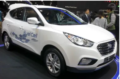
However, South Korean manufacturer Hyundai launched in 2012 the Hyundai Tucson ix35 FCEV, the first mass produced fuel cell vehicle. Already available on South Korea and USA, the Tucson is to be made available on fifteen countries worldwide this year.
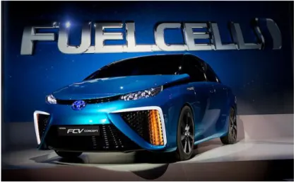
Japanese manufacturer Toyota also launched a fuel cell powered vehicle, the Toyota Mirai. Like the Hyundai, the Mirai was initially only available on its home country, but has since expanded sales to the USA and is expected to launch in some EU country this year [16].
Figure 2.15 – The Toyota Mirai is one of the first fuel-cell powered vehicles for common users.
2.2.3 Advantages of Proton Exchange Membrane Fuel Cell
Hydrogen advantage as a fuel
Environment friendly
Hydrogen is probably the more environmentally friendly fuel available right now. The only byproduct of using a PEMFC is water and hydrogen isn’t even toxic, causing no harm to the planet.
Fuel Efficient
Hydrogen is one of the most powerful and efficient fuel. Compared to gasoline or methanol, hydrogen produces more energy per kilogram. Theoretically, an amount of hydrogen could take a fuel-cell powered car twice as far as a car running on the same amount.
Easy production
Hydrogen is the most abundant element in the universe and can easily be produced locally from several sources, like biomass, coal or water. Electrolysis is one of the best way to obtain hydrogen from water.
Proton Exchange Membrane Fuel Cell advantages relative to batteries
PEMFC can be seen as one of the biggest challenger to the lithium batteries, particularly on electric vehicles. PEMFC introduces several advantages relative to lithium batteries that can be exploited by fuel cell powered vehicles.
PEMFC have the highest energy density of all the fuel cells, which means more power available to the user or a bigger mileage for the same consumed fuel. For example, the Toyota Mirai has a performance of about 3.5 l/100 km of fuel, while the similar Prius, with electric and gasoline motor, has a performance of 4.2 l/100 km, while having a smaller engine.
PEMFC also introduces other advantages, being more compact than lithium batteries and being generally simpler. PEMFC charging is also a lot simpler and faster than lithium batteries, needing only to add more fuel to have more available power [17][17][18].
Proton Exchange Membrane Fuel Cell advantages relative to combustion motors
PEMFC may be the strongest competitors that combustion motors have encountered. PEMFC are considered the next big thing as a vehicle power supply, with several manufacturers having prototypes ready and even some with commercial models available.
Like with lithium batteries, the high energy density of PEMFC and Hydrogen is a great advantage, allowing a better fuel consumption ratio when compared with pure combustion moto. As example, the Hyundai Tucson ix35 PEMFC powered vehicle has a performance of 4.8 litters of fuel for each 100 km done, while the diesel version has a 6.8 l/100km performance and the petrol version has a 6.4 l/km performance, with a weaker engine.
Figure 2.17 – The Hyundai Tucson PEMFC powered shows a better performance when compared with diesel or petrol version
PEMFC have also a lower maintenance need and a higher reliability has they have few, sometimes none, moving parts, contrary to combustion motors. They are completely silent, even coupled with electric motors, as opposed to combustion motors.
However, the biggest benefit relative to combustion motors is the fact that PEMFC are totally green, only producing water as a byproduct, with no greenhouse gas. Hydrogen is also a renewable fuel, amply available [20].
2.2.4 Problems with Proton Exchange Membrane Fuel Cell
PEMFC, like other fuel cell technologies, have progressed greatly since their invention, but still need more work to have a true breakthrough that establishes them as a true alternative on the energetic world.
Hydrogen disadvantages as a fuel
Expensive
While hydrogen is, in theory, a great fuel and an easy one to obtain, due to the frequency it occurs on the universe, hydrogen production is highly expensive. Right now, liquid hydrogen is used as fuel and the process used to liquefy hydrogen is a costly one.
A way to cheapen the process is using high-pressure gas hydrogen, like the new fuel cell vehicles do, but even then it’s still more expensive that other fuels. To compare, a full tank of compressed hydrogen for the Toyota Mirai, corresponding to 485 km of range, costs about 50$, while for the same range, a Toyota Prius only need 21$ of fuel, the average driver needs 44.5$ and an electric vehicle like the Tesla Model S costs only 9.6$[21].
Also, hydrogen production, transportation, distribution and storage is still difficult and expensive, even with costs lowering with evolution of hydrogen production techniques.
Highly Flammable
Hydrogen is a powerful fuel, but this also bring disadvantages. Hydrogen is one of the most flammable fuel actually available and can be dangerous.
Almost no infrastructure
While fuel cell and hydrogen vehicles have always been seen as the future of transportation, efforts to bring infrastructures to support them as been very small or even null. This has slowly been improving, with 100 hydrogen station being expected in Japan by the end of this year, 50 on Germany by mid-2015, 21 on South Korea by 2020 and 28 station on California by 2016.
Other countries are starting to open new hydrogen fueling station, with UK, Iceland, Turkey, Netherlands, Canada, Denmark or Norway also having at least one public hydrogen fueling station open right now.
Still dependent on fossil fuels
While hydrogen consumption as a fuel is clean of greenhouse gases, the process to harness hydrogen from water or other compounds still uses many fossil fuels. Coal, oil and natural gas are the most used nowadays, but electrolysis is showing prospect to be a decisive factor to cut the need of fossil fuels.
Water and Carbon Monoxide management
Fuel cells are highly sensitives to contamination that hamper their performance. Every kind of fuel cell is sensitive to some specific topics and PEMFC are sensitive to carbon monoxide contamination.
Contamination comes via hydrogen fuel. Commonly, Hydrogen fuel is produced not by electrolysis, that produces “clean” hydrogen, but by steam reforming coal or natural gas hydrocarbons, that result in a mixture of gases, including monoxide carbon.
Platinum, the main compound of the catalyst on the membrane is easily poisoned by carbon monoxide. One part per million is the maximum acceptable value of CO that can go poison the catalyst. To counter this, platinum-ruthenium catalyst were implemented, that made the maximum acceptable value of CO increase ten times, but still easily attainable.
Water management is another problem on PEMFC. The membrane must be humid for it to work, but with operating temperature exceeding the 60 ºC, that is hard to achieve. Also, while the membrane must be humid, it can’t be flooded with excessive water, which happens on the GDL. An equilibrium must be achieved to maintain the membrane humid without excessive water.
Heat dissipation
Besides producing output current, all fuel cell technologies also produce heat output that deteriorates the fuel cell electrical performance. PEMFC efficiency is about 40%, with 60% energy lost in heat form. With the increase of heat output, the electric output lowers, so a heat dissipation is needed to increase the cells efficiency.
As alternative, PEMFC are being used as CHP, using the heat produced by the cell as a positive output, not as a loss of efficiency.
2.2.5 Future of Proton Exchange Membrane Fuel Cell
While PEMFC were once seen as the future of the portable power supply, constant evolution on batteries have been constantly delaying PEMFC evolution. Heavy investments by key players in the electric market, like Japan, Germany and USA, have brought back the PEMFC as an alternative to lithium batteries and combustion motors.
2016 and 2017 are supposed to be the breakthrough years for fuel cell vehicles. With the already successful launch of the Toyota Mirai and Hyundai ix35 FCEV this year, more manufacturers are expected to launch fuel cell powered vehicles in the near future, with Honda, one of the pioneers of fuel cell research for vehicles, expecting to launch a new fuel cell vehicle in 2016, after successful testing in California on 2008.
Static PEMFC are also looking as strong as ever, with Japan in the front of the run. The DENO CHP program brought more than 13000 static PEMFC to Japanese homes, but more sales and evolution are expected these next years.
Small sized PEMFC have been, however, practically substituted by DMFC, as these are cheaper to make and can be better for these kind of applications.
2.3 Direct Methanol fuel cell
As previously mentioned, DMFC are one of the most recent and promising fuel cell designs and is one of the strongest candidates to replace common lithium batteries on the long run.
2.3.1 Direct Methanol Fuel Cell emergence
While the DMFC itself was only created on the 90s, methanol electro-oxidation was first researched in 1922 by E.Muller. In the early 1950s, investigations to create a methanol based fuel cell were started. The great struggle was finding what electrolyte and catalyzers could be used with methanol. Firstly, alkaline electrolyte were used, the most common at the time, but acidic electrolytes were also tested.
The incorporation of platinum as a catalyst, following the works of Cathro and of Jansen and Molhuysen, in the 1950s, and Watanabe and Motoo, in the 1960s, gave hope to the achievement of creating a methanol based fuel cell. Many studies were made to develop the methanol electro-oxidation, from the 60s to the 90s, with other improvements being made to both catalyzers, anode and cathode. The creation of several analysis techniques, like spectro-electrochemical studies or low-energy ion scattering, improved the capability of these groups to investigate certain properties of primordial DMFC.
The 1990s started a new era for the DMFC. All previous studies converged and culminated into the creation of the first real methanol based fuel cell by Dr. Surya Prakash, a superacid specialist, and Dr. George A.Olah, a Nobel laureate, both from the University of South California. Prakash and Olah cell was the first fuel cell able to convert methanol into electricity directly. Following this development, the University of South California and the Jet Propulsion Laboratory, in a collaborative effort, created the first true DMFC with a Nafion membrane, presenting it in 1992.
2.3.2 Direct Methanol Fuel Cell applications
DMFC were the first to bring the possibility of using fuel cells as substitutes to common lithium-ion batteries. Using methanol as a fuel bring great advantages, as it is a liquid fuel, easier to refill, which enables the system to be simplified. However, efficiency is sacrificed on DMFC, when compared to common PEMFC or other fuel-cells. Lower power, but higher energy density are characteristics that make DMFC ideal to portable electronic applications.
The prospect of using DMFC as an alternative energy source for electronic devices to lithium batteries, whose capacities are reaching their physical limits, mean that there were a great investment, from institutes, university and even manufacturers in this area [22].
Different studies to integrate DMFC on both MP3 players and PDA were realized by the Faculty of Industrial Design Engineering of the Delft University of Technology. While the first showed up that DMFC has much to improve to be able to challenge lithium batteries [23], the second was able to show that DMFC can be on par with these same lithium batteries and still be improved [24].
Another possible use of DMFC is using it as a charger instead of a direct power supply. Lithium batteries are used as such, with high capacities, but DMFC can also be used in this fashion, as Toshiba showed up with the Dynario.
Unfortunately, after years where DFMC was promised to be the next big thing, progress has been very slow. While in the mid 2000’s, many manufacturers were investing on DMFC research, one company has taken over the whole DMFC monopoly, SFC Energy, which reduced the progress of this technology.
Toshiba Dynario
The Toshiba Dynario was the first commercial DMFC charger. The Dynario was developed from 2003 to its limited launch, on 2009. The Dynario is a DMFC charger able to charge multiple devices via USB port. With an output of 5 V and 500 mA, the Dynario was incompatible with several devices and was bigger than expected, with its 14ml reservoir only able to charge a cell phone two times. Also, with a cost of approximately 325$ for the charger and of 150$ for 5 refill cartridge of 50 ml, and only 3000 units produced and sold exclusively on Japan, the Dynario was extremely expensive and rare, but was also the first commercial device that showed up the whole potential of DMFC technology [25].
Figure 2.18 – The Toshiba Dynario was one of the first DMFC powered devices available to the mass market. It failed to gain traction.
Apple’s DMFC Patents
IT giant Apple Inc. was always interested on fuel cell technology because of its promise to overthrow lithium ion batteries on the long run, however, only on 2011 Steve Jobs company took steps on this direction, registering on the United States Patent and Trademark Office four patents trademark involving DMFC, some suggesting the possibility of a DMFC powered Macbook laptop [26], [27]. Last July, new rumors came forth with the possibility of Apple introducing fuel cell technology on their laptop, in partnership with Intelligent Energy, a British fuel cell developer [28].
2.3.3 Advantages of direct methanol fuel cells
DMFC are regarded as one of the few technologies that can compete with lithium batteries in the near future. DMFC and methanol presents several advantages when comparing them with other power sources.
Methanol advantages as a fuel
Methanol is the key element that makes DMFC the most promising fuel cell design for low power application. Methanol holds several advantages when comparing to other fuels or power supply.
High octane rating and high flash point
Methanol has a higher octane rating that other fuels, 102. Comparing, gasoline has an octane rating that ranges 86 to 98 and ethanol has an octane rating of about 94. This makes methanol one of the least volatile fuels, avoiding accidents.
High energy density
Methanol as an enormous energy density of about 6000 Wh/kg. When comparing with the best lithium ion polymer, with an energy density of 600 Wh/kg on a best case scenario, methanol as a theoretical 10-fold superiority.
Easy to transport, distribute and produce
Methanol is a liquid that is as easy to transport and distribute as gasoline or other fuels. Also, it is cheaper to produce than gasoline, being based on natural gas instead of petrol.
Environmentally friendly
Methanol is one of the greener fuel available nowadays. As a molecule, methanol is easily biodegraded without environmental harm. While toxic when ingested in large quantities, methanol is water soluble and is easily disposed that way.
The methanol economy
Methanol has been, for years, suggested as the natural substitute for petrol as a fuel source. George A. Olah, one of the creators of the first methanol based fuel cell and a Nobel Prize winner, was the first advocator of methanol economy as a future economy scenario where methanol substitutes petrol, based on methanol’s advantage as a fuel by itself or as a way to produce hydrogen [28] [29] [31].
Figure 2.19 – All the methanol advantages brought the possibility of the creation of a methanol based economy, instead of the tradicional oil based economy
Direct methanol fuel cells advantages relative to batteries
DMFC main competitor is the common lithium battery that power almost every portable device actually commercially available.
The main advantage of DMFC is its higher energy density, result of methanol’s usage. This translate into greater operating time for portable devices such as laptops or cell phones and also into greater power availability, which can translate into higher performance.
This is not, however, the only advantage of DMFC technology. DMFC have the potential to be smaller and lighter than lithium batteries. They are also simpler in design, which can result, on the long run, into lower production costs.
Another great advantage is the possibility to instantly recharge your device. While lithium batteries take hours to charge, DMFC can be recharged simply by inserting more fuel, as a cartridge or directly into the cell.[32]
Direct methanol fuel cells advantage relative to gasoline combustion motors
While DMFC are not the principal fuel cell technology used in vehicles, it can be implemented as well as PEMFC, sharing similar configuration and design. DMFC powered vehicles are rare, with PEMFC dominating this realm, but DMFC also introduce certain advantages when comparing with gasoline combustion motors.
DMFC powered electric motors are cleaner than gasoline combustion motors, as the only reaction byproduct of a DMFC is water, being a zero emission fuel technology. DMFC have also a greater kilometer range when comparing with ion battery powered vehicle. When comparing with PEMFC, methanol is cheaper than hydrogen and easier to store.
2.3.4 Problems with direct methanol fuel cells
While DMFC are still viewed as one of the energy technology with the most future potential, they are still many problems that need to be solved for a breakthrough in the market to happen.
Methanol disadvantages as a fuel
While methanol as many advantages as a fuel, it is not without its disadvantages.
Lower energy density
While methanol as a higher energy density than lithium, it is still lower than gasoline, which is a disadvantage for DMFC powered vehicle.
Least volatile
While methanol being less volatile than gasoline is an advantage in preventing accidents, it also difficult the startup process, needing significantly more heat to do so.
More expensive
Methanol is more expensive than gasoline nowadays, although there is a possibility that the price can lower if production and need increase.
Corrosive
Methanol is highly corrosive and reactive to certain materials, like plastic and many metals, like aluminum, zinc and manganese.
No infrastructures
There is virtually no infrastructure for methanol usage as a fuel. Without infrastructures, methanol cannot become a valid fuel.
Methanol crossover
Methanol crossover is one of most problematic phenomenon occurring on DMFC. While using higher methanol concentration provides higher energy density, it also allows methanol leaks to the membrane, reducing the cells performance due to this methanol leak mixing with the cathode. Through this, the methanol pass through the membrane and are directly oxidized by the oxygen on the cathode [33].
This causes two simultaneous problems:
a) Higher methanol consumption and higher heat output without higher current output.
b) Severe decline of the cathode voltage.
Heat dissipation
Methanol oxidation causes a heat output, besides the current output. The efficiency of DMFC is about 30%, which means that 70% of the energy is loss as heat. The higher the heat output on the DMFC, the lower the output electric energy is. As such, a heat dissipation way is needed to increase the practical efficiency of the cell.
Low energy density
While methanol by itself as good energy density, 10 times above the existing in lithium, the cell by itself has not an energy density as good.
DMFC can be passive systems, without requiring additional equipment. This cell simplicity can play against itself, as the fuel and carburant supply can vary during the cell’s usage and affect negatively the cell’s performance. Also, carbon dioxide accumulation on the anode and water accumulation on the cathode diminish the contact superficies to allow the oxidizing reaction to occur.
The way to solve this problem is using pumps to maintain a constant flow of fuel and air, but with costs in terms of power consumption.
2.3.5 Direct Methanol Fuel Cell future
The increase of lithium battery capacity, as the usage of new kinds of batteries, like lithium ion or lithium polymer, and the reduction of power consumption from electronic devices, due to the improvement and advancement of manufacturing processes, have been key factors to the stagnation of DMFC development. However, lithium battery capacity increase is now reaching a physical limitation, since it is necessary to significantly increase the size thereof to increase its capacity, clearly a negative point in a time where the evolution of electronic devices tends toward a decrease in dimensions, especially in thickness. Power consumption decrease is also slowing down, as manufacturers are still searching for ways to keep the performance of their product increasing, even when reaching the minimum limit on the size of a transistor on silicon.
Due of this, DMFC can catch up and regain a bright future in the field of portable equipment power supply. While still having technical problems to solve, DMFC can be smaller, better, less-costly, with a lower ecological footprint and higher efficiency when compared to lithium batteries. Refueling of DMFC can be fast and cheap, keeping a DMFC cost competitive on a long run analysis [34].
3. T
HEORETICAL
S
TUDY
3.1 Fuel Cell
Although initially the creation of a DMFC was intended for this project, the timeline dictated that it was a better choice to use an existing fuel cell, in this case a PEMFC, adapting it to be powered by methanol, instead of pure hydrogen, essentially turning it into a DMFC. This conversion would not interfere with the following work, as the fuel cell would work as any other DMFC.
3.1.1 The given PEMFC
The used PEMFC is a Horizon model, the Horizon Mini PEM Fuel Cell. The Mini PEM Fuel Cell is a model created for an education purpose with design as shown on figure 3.1 and specifications as shown on table 1. The Mini PEM Fuel Cell can be obtained for 239€ for a five units set, in the Horizon online store [35].
Table 1 – Horizon Mini PEM Fuel Cell properties [35].
Fuel Cell Properties
Output Voltage 0.6 V (DC) Output Current 0.45 A Power 270 mW Color Blue Dimensions 32 x 32 x 32 mm Total Weight 27.3 g
About Horizon Fuel Cell Technologies, they are a company founded in 2003 in Singapore that specializes on PEMFC, from multi-kilowatts PEMFC to both sub-watts and micro-size PEMFC. They are responsible for the creation of various science experiment kits, like the one used on this dissertation, as for several other fuel cell kits for usage in the automotive or aerospace industry, for example. They are currently the world largest producer of sub-megawatts fuel cells. More information can be obtained on their website [36].
3.1.2 Operating principle of PEMFC
As previously referred, PEMFC is one of the simpler and most promising design. They were also the first fuel cell design that used a membrane, more accurately a polymer electrolyte membrane (PEM), as electrolyte, and creating the notion of Membrane Electrode Assembly (MEA), also used on DMFC.
Membrane Electrode Assembly
The MEA is a central piece of both PEMFC and DMFC, and can be of three kinds: the MEA3 that is composed of the PEM and catalyst layers, the MEA5 that adds two GDL and the MEA7, with two sealing layers.
Figure 3.2 – Composition of the MEA [37].
The MEA is by far the most expensive component of a PEMFC, ranking roughly 75% of the total PEMFC cost. The MEA function is essentially the combined function of all its component combined, and must be able to allow hydrogen ions, or protons, through the membrane, without allowing both H2 and O2 gases to contact with each other, must be able to be hydrated, so that
ion penetration happens and must be able to operate at high temperatures.
The performance of the whole PEMFC is closely related with the MEA’s performance. To improve performance, several manufacturers are working with the material used on the PEM (usually Nafion®), others are changing the fabrication method [38].
Polymer Electrolyte Membrane
The PEM is the central part of the MEA, being the electrolyte used by PEMFC. The PEM can be made of different materials, but the most used one is Nafion®, from Dupont. Other used materials are perfluorinated ionomer membranes and Dow membranes, from Dow Chemical Company.
Figure 3.3 - A Nafion® membrane from Dupont.
A membrane must have considerable properties to be used as PEM on a PEMFC.
Chemical and electrochemical stability in fuel cell operating conditions;
Elevated proton conductivity to support high currents with minimal resistive losses and zero electronic conductivity;
Good water uptakes at temperatures of approximately 100 ° C, the operating temperature;
Thermal and hydrolytic stability;
Chemical properties compatible with the bonding requirements of the MEA;
Extremely low permeability to reactant species to maximize efficiency;
Mechanical strength and stability in the operating conditions;
Resistance of fuel transport through it;
High durability;
Facilitation of rapid electrode kinetics;
Flexibility to operate with a wide range of fuels;
Production cost compatible with the commercial requirements of the fuel cell;
Other effects also take place that can affect the overall performance of the fuel cell like the cell’s water management and the membrane thickness [38].
Membranes are still evolving so that PEMFC can become an even better power solution for the future. Right now, a Dow membrane, one of the highest performers available, cost in between 800 and 2000$ per m2, while Nafion® 117, the highest performer from Dupont, can exceed
![Figure 2.1 – Grove’s Gas Voltaic Battery is considered the first fuel cell in history [1]](https://thumb-eu.123doks.com/thumbv2/123dok_br/17561187.817400/26.892.279.616.103.380/figure-grove-gas-voltaic-battery-considered-fuel-history.webp)
![Figure 2.4 – A bacon fuel cell was chosen by NASA to provide energy for the Apollo spatial module [4]](https://thumb-eu.123doks.com/thumbv2/123dok_br/17561187.817400/27.892.344.550.769.1027/figure-bacon-chosen-provide-energy-apollo-spatial-module.webp)
![Figure 2.10 - Reactions and products of a proton exchange membrane fuel cell [12].](https://thumb-eu.123doks.com/thumbv2/123dok_br/17561187.817400/34.892.214.679.676.928/figure-reactions-products-proton-exchange-membrane-fuel-cell.webp)
![Figure 2.13 – General Electric was responsible for the PEMFC powering the Gemini project [14]](https://thumb-eu.123doks.com/thumbv2/123dok_br/17561187.817400/36.892.134.756.627.871/figure-general-electric-responsible-pemfc-powering-gemini-project.webp)

![Figure 3.2 – Composition of the MEA [37].](https://thumb-eu.123doks.com/thumbv2/123dok_br/17561187.817400/55.892.194.700.106.364/figure-composition-mea.webp)

![Figure 3.6 - The Bartels MP5 Micropump [46].](https://thumb-eu.123doks.com/thumbv2/123dok_br/17561187.817400/61.892.257.636.105.365/figure-bartels-mp-micropump.webp)